
Related Manuals for Honda HHT31S


Summary of Contents for Honda HHT31S
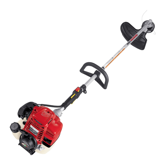
- Page 1 Owner's Manual Trimmer/Brush Cutter HHT25S • HHT31S See page 42 for instructions on assembling your Trimmer. © 2002, 2003 American Honda Motor Co., Inc.—All Rights Reserved...
- Page 2 The information and specifications included in this publication were in effect at the time of approval for printing. American Honda Motor Co., Inc. reserves the right, however, to discontinue or change specifications or design at any time without notice and without incurring any obligation whatever. No...
- Page 3 INTRODUCTION Congratulations on your selection of a Honda trimmer/brush cutter. We are certain you will be pleased with your purchase of one of the finest trimmer/brush cutters on the market. We want to help you get the best results from your new trimmer/brush cutter and to operate it safely.
- Page 4 INTRODUCTION A FEW WORDS ABOUT SAFETY Your safety, and the safety of others, are very important. And using this trimmer/brush cutter safely is an important responsibility. To help you make informed decisions about safety, we have provided operating procedures and other information on labels and in this manual.
-
Page 5: Table Of Contents
STARTING THE ENGINE ........17 STOPPING THE ENGINE........19 TRIMMER/HARNESS QUICK DISCONNECTION... 19 TRIMMER OPERATION ..........19 SAFE OPERATING PRACTICES ......21 OPERATING TIPS ...........22 SERVICING YOUR HONDA TRIMMER ....24 THE IMPORTANCE OF MAINTENANCE ....24 MAINTENANCE SAFETY ........24 MAINTENANCE SCHEDULE........25 ENGINE..............26 CUTTING ATTACHMENTS ........29 FUEL SYSTEM ............40... -
Page 6: Trimmer Safety
To prevent injury to others, keep people at least other property. 50 feet (15 meters) away from the working area These Honda trimmers are intended for use by during operation. gardening professionals. Never allow children to Always Wear the Harness When Trimming operate the trimmer. -
Page 7: Attachments & Modifications
Attachments brush cutter. Your Honda trimmer servicing dealer has cutting If you decide he/she is, make sure the attachments, debris shields, barrier kits, and employee(s) read and understand all instructions... -
Page 8: Safety Label Locations
The labels shown here contain important safety information. Please read them carefully. These labels are considered permanent parts of your trimmer/brush cutter. If a label comes off or becomes hard to read, contact an authorized Honda servicing dealer for a replacement. TYPE EQUIPPED WITH... -
Page 9: Recommended Cutting Attachments
The shield’s cutoff knife automatically removes any excess line that is released from the cutting head. Honda HHT31SUNBA model trimmers are supplied with two different debris shields. Use the debris shield with the cutoff knife when the cutting-line head is installed. -
Page 10: Blades And Shields
RECOMMENDED CUTTING ATTACHMENTS BLADES AND SHIELDS DEBRIS SHIELDS A variety of blades are available from your Honda BLADE CUTTING-LINE trimmer servicing dealer. Always use a debris CUTOFF KNIFE shield designed for use with a blade when GRASS/WEED BLADE, attaching a blade to your trimmer. The blade type... -
Page 11: Cutting Attachment Applications
THICK WEEDS AND LIGHT BRUSH WOODY BRUSH, SHRUBS, SAPLINGS Your Honda trimmer servicing dealer has cutting attachments that have been designed and approved for your trimmer and are covered by warranty. Non-Honda attachments are usually designed for universal applications. Although aftermarket attachments may fit on your trimmer, they may not meet... -
Page 12: Controls & Equipment
CONTROLS & EQUIPMENT COMPONENT & CONTROL LOCATIONS CUTTING-LINE HEAD GEAR CASE HHT25SLTA LOOP HANDLE HARNESS HANGER SPARK PLUG THROTTLE SET BUTTON Refer to page 37 for OPERATOR spark plug access. PRESENCE CHOKE LEVER DEBRIS SHIELD WITH LEVER CLEANER CUTOFF KNIFE SPARK COVER ARRESTER... -
Page 13: Controls
CONTROLS & EQUIPMENT CONTROLS CHOKE LEVER The location and operation of the controls are similar on both the HHT25S and HHT31S CLOSED models. Choke Lever The choke lever opens and closes the choke OPEN valve. The CLOSED position enriches the fuel mixture for starting a cold engine. - Page 14 CONTROLS & EQUIPMENT Throttle Set Button THROTTLE SET BUTTON The throttle set button is used to hold the throttle trigger at the fast idle position for starting. Do not THROTTLE allow the cutting line or blade to contact any TRIGGER OPERATOR obstruction when starting the engine with the PRESENCE...
-
Page 15: Equipment
(American National Standards Institute) standard QUICK-RELEASE LATCH Z87.1 must be worn by the operator of any Honda trimmer/brush cutter. The safety glasses supplied with each new Honda HHT25S and SAFETY GLASSES (ANSI Z87.1) HHT31S trimmer/brush cutter complies with this ANSI standard. -
Page 16: Before Operation
BEFORE OPERATION ARE YOU READY TO OPERATE THE TRIMMER? Your safety is your responsibility. A little time Hearing Protection spent in preparation will significantly reduce your Hearing protectors will help to protect your ears risk of injury. from noise. Earmuff-style hearing protectors can also protect your ears from thrown objects. - Page 17 BEFORE OPERATION IS YOUR TRIMMER READY TO GO? For your safety, and to maximize the service life Cutting Attachment Inspection of your equipment, it is very important to take a • Look for signs of damage to the cutting few moments before you operate the trimmer to attachment (see pages 29 and 35).
- Page 18 BEFORE OPERATION ARE YOUR SHOULDER HARNESS AND TRIMMER CORRECTLY ADJUSTED? Adjusting the Harness Balancing the Trimmer on the Shoulder Harness Adjust the harness so the quick-release latch is at your right hip, as shown. Hang the trimmer on the harness hook, and see how it balances.
-
Page 19: Operation
OPERATION SAFE OPERATING PRECAUTIONS Before operating the trimmer for the first time, please review the IMPORTANT SAFETY INFORMATION chapter on page 4 and BEFORE OPERATION chapter starting on page 14. Even if you have operated other trimmers, take time to become familiar with the operation of this trimmer’s controls and handling. - Page 20 The cutting-line head or blade should not rotate with the engine idling. If there is rotation HOOK at idle, adjust the idle speed correctly before using the trimmer. For idle adjustment, consult your authorized Honda servicing dealer.
-
Page 21: Stopping The Engine
OPERATION STOPPING THE ENGINE STOP (O) 1. Release the throttle trigger. THROTTLE TRIGGER 2. Move the ignition switch to the STOP (O) position. IGNITION SWITCH Wait for the cutting line head or blade to stop before allowing the end of the trimmer to contact anything. - Page 22 OPERATION Throttle Operation Pull the throttle trigger toward the grip to increase engine speed and start cutting attachment rotation. The trimmer has the greatest cutting force at THROTTLE TRIGGER maximum engine speed. Release the throttle trigger to reduce engine speed. At idle, the cutting attachment should coast to a stop.
-
Page 23: Safe Operating Practices
The trimmer will throw debris in the direction of applications. blade movement at the point of contact. If using a blade on a Honda trimmer equipped The cutting line head or blade on Honda HHT25S with a loop handle, also install the optional Honda... -
Page 24: Operating Tips
Blades on Honda HHT25S and HHT31S trimmers rotate counterclockwise, as viewed from the operator’s position. Therefore, the left side of the blade is moving toward you. With these trimmers, sawing with the left side of a brush blade will give you better control and less risk of kickback, though it will throw the sawdust toward you. - Page 25 OPERATION Trimming and Edging Use nylon line for cutting against a hard surface. Work from an angle where debris that strikes the hard surface will ricochet away from you. DEBRIS Avoid contact with wires, wire fences, metal rods, etc. Overlapping a wire will cause the nylon line to wrap around the wire and break off.
-
Page 26: Servicing Your Honda Trimmer
To reduce the possibility of fire or explosion, To ensure the best quality and reliability, use only be careful when working around gasoline. new, genuine Honda parts or their equivalents for Use only a nonflammable solvent, not repair and replacement. -
Page 27: Maintenance Schedule
(1) Service more frequently when used in dusty areas. (2) These items should be serviced by your servicing dealer, unless you have the proper tools and are mechanically proficient. Refer to the Honda shop manual for service procedures. (3) Log hours of operation to determine proper maintenance intervals. -
Page 28: Engine
SERVICING YOUR HONDA TRIMMER ENGINE Engine Oil Level Check Check the engine oil level before each use, or every 10 hours if operated continuously. Rest the trimmer on a level surface, with the engine FILLER OPENING (HHT31S) stopped and in an upright position. - Page 29 The recommended operating range extends from 23°F (-5°C) to 104°F (40°C). The SAE oil viscosity and service classification are on the API label on the oil container. Honda recommends that you use API SERVICE category SJ or SL oil.
- Page 30 Throttle Cable Inspection Verify the throttle trigger operates smoothly and the throttle cable is undamaged. If there is visible damage, or if the throttle trigger does not operate smoothly, have your authorized Honda servicing dealer replace the throttle cable. Check the free play at the end of the throttle cable.
-
Page 31: Cutting Attachments
Cutting-Line Heads line. Using non-Honda line may result in increased noise levels. All Honda trimmers come with either a manual or semi-matic cutting head. Read this section to For original, factory-installed Honda cutting-line learn how to inspect, install new line, and remove heads, use only nylon monofilament line in the and install a cutting head from the trimmer. - Page 32 SERVICING YOUR HONDA TRIMMER Manual Cutting-Line Head 1. Clean any mud, dirt, debris, etc. from the area around the trimmer head; otherwise, it will make it more difficult to service. 2. Rotate the left-hand threaded knob in the HOUSING direction of the arrow and remove the knob.
- Page 33 SERVICING YOUR HONDA TRIMMER 5. When you have about 6 inches (150 mm) of line remaining, press the lines into the two notches on the bottom of the spool. This will hold the lines on the spool for reassembly. NOTCHES 6.
- Page 34 SERVICING YOUR HONDA TRIMMER Semi-Matic (Bump-Feed) Cutting-Line Head SPOOL 1. Clean any mud, dirt, debris, etc., from around the trimmer head area; otherwise, it will make it more difficult to service. 2. Locate the half-round locking hole on the spool.
- Page 35 SERVICING YOUR HONDA TRIMMER 7. Wind both lines tightly and evenly from side to side ignoring the ridge. Feed the line while turning the spool in the direction of the arrow. Do not allow the line to get twisted. It is important to prevent the two lines from getting twisting over each other.
- Page 36 SERVICING YOUR HONDA TRIMMER Removal & Installation This section shows you how to remove and install either style trimmer head from your trimmer. REMOVAL DIRECTION 1. Insert the tip of a commercially available 4 mm hex wrench or equivalent fully into the gear case hole.
- Page 37 A torque wrench is required to install the blade. If A worn, damaged or cracked blade can break, you do not have a torque wrench, have a Honda and pieces of the damaged blade can become trimmer servicing dealer tighten the blade lock dangerous projectiles.
- Page 38 SERVICING YOUR HONDA TRIMMER 1. Install the protective plastic cover, that came with the blade, back on the blade. 2. Insert a commercially available 4 mm hex tool LOOSEN or equivalent fully into the gear case hole. TIGHTEN COVER 3. Turn the blade until you feel the tool drop into SPACER B the hole in cover plate/spacer A.
- Page 39 SERVICING YOUR HONDA TRIMMER Spark Plug Service SPARK PLUG Recommended spark plugs: HHT25S CMR5HSB (NGK) HHT31S CR5HSB (NGK) HHT31S U16FSR-UB (DENSO) NOTICE Incorrect spark plugs can cause engine damage. 1. HHT25S model: Remove the 5 x 12 mm hex SPARK PLUG CAP bolt and top cover.
- Page 40 SERVICING YOUR HONDA TRIMMER Spark Arrester Service RECOIL STARTER HHT31S The spark arrester must be serviced every 100 hours to keep it functioning as designed. If the engine has been running, the muffler will be very hot. Allow the muffler to cool before servicing the spark arrester.
- Page 41 SERVICING YOUR HONDA TRIMMER HHT25S The spark arrester must be serviced every 100 hours to 5/32 in (4 mm) HEX WRENCH (commercially available) keep it functioning as designed. If the engine has been running, the muffler will be very 5 x 12 mm hot.
-
Page 42: Fuel System
Spilled fuel is not only a fire hazard, it causes of gasoline. If spark knock or pinging persists, environmental damage. Wipe up spills see an authorized Honda servicing dealer. immediately. NOTICE Move at least 10 feet (3 meters) away from the Running the engine with persistent spark knock fueling source and site before starting the engine. - Page 43 SERVICING YOUR HONDA TRIMMER Fuel Filter and Fuel Tank Cleaning 1. Remove the fuel tank cap, and empty the fuel tank into an approved gasoline container. Use a funnel to avoid spilling gasoline. 2. Pull the fuel filter out through the fuel filler neck by hooking the black fuel supply tube with a piece of wire, such as a partly straightened paper clip.
-
Page 44: Assembly
ASSEMBLY After assembly and before operation review the Safe Operating Precautions on page 17. IMPORTANCE OF PROPER ASSEMBLY Proper assembly is essential to operator safety WARNING and the reliability of the machine. Any error or oversight made by the person assembling and Improper assembly can cause an servicing a machine can result in faulty operation, unsafe condition that can lead to... -
Page 45: Unpacking
A 4 mm hex wrench, 8 and 17 mm sockets, 0 to 25 ft-lb torque wrench. LOOSE PARTS Check all loose parts against the following list. Contact your authorized Honda servicing dealer if any of the loose parts shown are not included with your trimmer. -
Page 46: Trimmer Assembly (Unba Types Only)
ASSEMBLY TRIMMER ASSEMBLY (UNBA types only) U-Shaped Handlebar Installation 1. Remove the four 5 x 28 mm bolt/washers and THROTTLE TRIGGER handlebar holder A. 5 x 28 mm BOLT/ WASHER(4) HANDLEBAR 2. Set the U-shaped handle into handlebar HOLDER A holder B with the throttle trigger facing to the right. - Page 47 ASSEMBLY Saw Blade The UNBA types are shipped with a manual nylon cutting-line head installed on the trimmer. If the saw blade is needed, move the ignition switch to the STOP (O) position and disconnect the spark plug cap from the spark plug. Wear protective gloves when working around the cutting-line head and saw blade. Cutting-Line Head Removal CUTTING-LINE HEAD 1.
- Page 48 ASSEMBLY Saw Blade Installation 1. Insert a 4 mm hex wrench or equivalent into the gear case hole to prevent the output shaft from turning. TIGHTEN COVER 2. Install cover plate/spacer A onto the output SPACER B shaft as shown. BLADE 10 mm LOCK NUT Install with the white...
-
Page 49: Blade Cover Removal
ASSEMBLY BLADE COVER REMOVAL 1. Turn the blade cover slowly until the POST cover latch is clear of the debris shield. Unfasten the latch by lifting the tab off the post. BLADE COVER 2. Pull the post end away from the blade and set it on top of the blade as shown. -
Page 50: Engine Oil
3. Screw in the oil filler cap/dipstick securely. LIMIT FUEL Refer to Refueling section of the SERVICING YOUR HONDA TIMMER chapter (page 40). BEFORE OPERATION On blade equipped UNBA types, always remove the blade cover before starting the engine. If the... -
Page 51: Storage
STORAGE STORAGE PREPARATION Fuel Gasoline will oxidize and deteriorate in storage. Proper storage preparation is essential to keep Old gasoline will cause hard starting, and it your trimmer trouble free and looking good. The leaves gum deposits that clog the fuel system. If following steps will help to keep rust and the gasoline in your trimmer deteriorates during corrosion from impairing your trimmer's function... -
Page 52: Storage Precautions
STORAGE Adding Fuel Stabilizer to Extend Fuel Storage STORAGE PRECAUTIONS Life If your trimmer will be stored with gasoline in the When adding a fuel stabilizer, fill the fuel tank fuel tank and carburetor, it is important to reduce with fresh gasoline. If only partially filled, air in the the hazard of gasoline vapor ignition. -
Page 53: Transporting
TRANSPORTING BEFORE LOADING If the engine has been running, allow it to cool for at least 15 minutes before loading the trimmer on the transport vehicle. A hot engine and exhaust system can burn you and can ignite some materials. Always turn the ignition switch to the STOP (O) position. -
Page 54: Taking Care Of Unexpected Problems
Clean, gap, or replace the incorrect gap. spark plug. Take trimmer to an Fuel filter clogged, carburetor Replace or repair faulty authorized Honda servicing malfunction, ignition malfunction, components as needed. dealer, or refer to shop valves stuck, etc. manual. ENGINE OPERATING PROBLEMS... -
Page 55: Cutting Head Problems
TAKING CARE OF UNEXPECTED PROBLEMS CUTTING HEAD PROBLEMS Blade or Cutting-line Possible Cause Correction head Won’t Stop Turning When Throttle is at SLOW Position Check throttle control and Fault in throttle control or cable; Check throttle control parts, cable. throttle cable out of adjustment or adjust or replace cable if bent. -
Page 56: Technical & Consumer Information
TECHNICAL & CONSUMER INFORMATION TECHNICAL INFORMATION This chapter contains important information about serial number locations, high altitude operation, oxygenated fuels, and emissions control systems. Serial Number Locations There are two serial numbers, one for the trimmer and one for the engine. Record these numbers in the space provided. - Page 57 TECHNICAL & CONSUMER INFORMATION Oxygenated Fuels Some conventional gasolines are being blended with alcohol or an ether compound. These gasolines are collectively referred to as oxygenated fuels. To meet clean air standards, some areas of the USA and Canada use oxygenated fuels to help reduce emissions. If you use an oxygenated fuel, be sure it is unleaded and meets the minimum octane rating requirement.
- Page 58 • Misfiring or backfiring under load react in the same way, but it is toxic. • Afterburning (backfiring) Honda utilizes lean carburetor settings and other • Black exhaust smoke or high fuel systems to reduce the emissions of carbon consumption monoxide, oxides of nitrogen, and hydrocarbons.
- Page 59 TECHNICAL & CONSUMER INFORMATION Air Index An Air Index Information hang tag/label is applied to engines certified to an emission durability time period in accordance with the requirements of the California Air Resources Board. The bar graph is intended to provide you, our customer, the ability to compare the emissions performance of available engines.
- Page 60 TECHNICAL & CONSUMER INFORMATION Specifications FEATURES HHT25S HHT31S HHT31SUNBA • GX25 1.1 hp • • GX31 1.5 hp • • Loop handle • U-type handle Manual feed head optional optional • Semi-matic feed • • optional head optional optional Saw blade •...
- Page 61 Spark plug gap Refer to page 37 (0.60 - 0.70 mm) Intake: 0.08 ± 0.02 mm HHT25S Exhaust: 0.11 ± 0.02 mm Valve clearance See your authorized Intake: 0.12 ± 0.02 mm (cold) servicing Honda dealer HHT31S Exhaust: 0.15 ± 0.02 mm...
-
Page 62: Consumer Information
CONSUMER INFORMATION Honda Publications Three other documents are available from your Dealer Locator Information Honda dealer. There is a shop manual and shop To find an Authorized Honda Servicing Dealer manual supplement, which covers complete anywhere in the United States: maintenance and overhaul procedures. -
Page 63: Index
INDEX Air Filter Emission Control System........56 Check ............27 Engine Cleaning ............ 27 Fuel Recommendations......40 Air Index............57 Ignition Switch ...........11 Assembly ............42 Oil Change..........26 Loose Parts ..........43 Oil Level.............26 Trimmer Assembly (UNBA types only)..44 Oil Recommendations .......27 Unpacking .......... - Page 64 INDEX Maintenance Safe Operating Practices ........21 Air Filter ............. 27 Safety Engine Oil..........26 Attachments and Modifications....5 Fuel System ..........40 Important Message to Employers....5 Importance ..........24 Important Safety Information .......4 Safety ............24 Safety Label Locations ........6 Schedule ........... 25 Safety Precautions..........17 Spark Arrester ...........
-
Page 65: Quick Reference Information
QUICK REFERENCE INFORMATION HHT25S HHT31S Type Unleaded gasoline with a pump octane rating of 86 or higher (page 40) Fuel Capacity 0.53 qt/16.9 fl oz (0.50l) 0.69 qt/22.0 fl oz (0.65l) Type SAE 10W-30, API SJ or SL (page 27) Engine oil Capacity 2.71 fl oz (80 cc) - Page 66 POM53509A IPC 10000.2003.07 31VJ4001 Printed on Printed in U.S.A. 00X31-VJ4-0010 Recycled Paper...