Yamaha EF6600DE - Premium Generator Owner's Manual
Owners manual
Hide thumbs
Also See for EF6600DE - Premium Generator:
- Owner's manual (66 pages) ,
- Theory & diagnostics manual (218 pages) ,
- Owner's manual (292 pages)

Related Manuals for Yamaha EF6600DE - Premium Generator


Summary of Contents for Yamaha EF6600DE - Premium Generator
- Page 1 Generator OWNER’S MANUAL EF4000DE EF5200DE EF6600DE YG4000D YG5200D YG6600D YG6600DE LIT-19626-01-15 7WV-28199-11...
- Page 3 AE00002 INTRODUCTION Congratulations on your purchase of your new Yamaha. This manual will provide you with a good basic understanding of the operation and maintenance of this machine. If you have any questions regarding the operation or maintenance of your machine, please consult a Yamaha dealer.
- Page 4 IS INVOLVED! your engine and this manual. If there is any question concerning this manu- al, please consult a Yamaha dealer. 9 This manual should be considered a Failure to follow WARNING instructions permanent part of this engine and...
-
Page 5: Table Of Contents
AE00041 CONTENTS PERIODIC MAINTENANCE ....25 LIMITED WARRANTY (EF- AND MAINTENANCE CHART ....25 EDL-SERIES) ........1 SPARK PLUG INSPECTION....27 LIMITED WARRANTY (EC- AND CARBURETOR ADJUSTMENT ..27 YG-SERIES) ..........2 ENGINE OIL REPLACEMENT ..28 LOCATION OF IMPORTANT LABELS.4 AIR FILTER ........29 SAFETY INFORMATION.......6 EXHAUST FUMES ARE FUEL COCK ........30 POISONOUS ........6 FUEL TANK FILTER......30... -
Page 6: Limited Warranty
RANTIES OF MERCHANTABILITY AND FITNESS authorized Yamaha consumer generator dealer FOR A PARTICULAR PURPOSE WHICH EXCEED will, free of charge, repair or replace, at Yamaha’s THE OBLIGATIONS AND TIME LIMITS STATED IN option, any part adjudged defective by Yamaha THIS WARRANTY ARE HEREBY DISCLAIMED BY due to faulty workmanship or material from the YAMAHA MOTOR CORPORATION, U.S.A. -
Page 7: Limited Warranty (Ec- And Yg-Series)
Yamaha industrial generator dealer OTHER WARRANTY KIND, will, free of charge, repair or replace, at Yamaha’s EXPRESSED OR IMPLIED. ALL IMPLIED WAR- option, any part adjudged defective by Yamaha RANTIES OF MERCHANTABILITY AND FITNESS due to faulty workmanship or material from the FOR A PARTICULAR PURPOSE WHICH EXCEED factory. - Page 8 Yamaha Motor exactly as specified in the Owner’s Manual? Corporation, U.S.A. by the selling dealer at the A. No. The warranty on a new Yamaha cannot time of your purchase. If you should move after be “voided” or “cancelled.”...
-
Page 9: Location Of Important Labels
THIS ENGINE CONFORMS TO PHASE 2 U.S.EPA REGULATIONS FOR SMALL NONROAD ENGINES. EMISSIONS COMPLIANCE PERIOD:CATEGORY A (EPA) 2179R SAE 10W-30 TYPE YAMAHA MOTOR CO. LTD zzz- ENGINE OIL: ENGINE AIR INDEX ( C a l i f o r n i a onl y ) LEAST CLEAN... - Page 10 THIS ENGINE CONFORMS TO PHASE 2 U.S.EPA REGULATIONS FOR SMALL NONROAD ENGINES. EMISSIONS COMPLIANCE PERIOD:CATEGORY A (EPA) SAE 10W-30 2179R TYPE YAMAHA MOTOR CO. LTD zzz- ENGINE OIL: ENGINE AIR INDEX ( C a l i f o r n i a onl y ) LEAST CLEAN...
-
Page 11: Safety Information
AE00071 SAFETY INFORMATION AE00072 EXHAUST FUMES ARE POISONOUS 9 Never operate the engine in a closed area or it 741-002 may cause unconsciousness and death within a short time. Operate the engine in a well ventilated area. AE00075 FUEL IS HIGHLY FLAMMABLE AND POISONOUS 9 Always turn off the engine when refuelling. -
Page 12: Electric Shock Prevention
9 Keep the machine at least 1 m (3 ft) from buildings or other equipment, or the engine may overheat. a 1 m (3 ft) 741-008a 9 Avoid operating the engine with a dust cover. 741-009 9 Be sure to carry the generator only by its carrying handle(s). -
Page 13: Connection Notes
Ground (earth) Lead Diameter: 0.12 mm (0.005 in)/ampere 10 Ampere → 1.2mm (0.05 in) å EF4000DE/YG4000D 741-065 B EF5200DE/EF6600DE/YG5200D/YG6600D/YG6600DE AE00088 CONNECTION NOTES 9 Avoid connecting the generator to commercial power out- let. 9 Avoid connecting the generator in parallel with any other generator. -
Page 14: Control Function
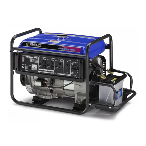
EF4000DE AE00101 CONTROL FUNCTION e q w AE00102 DESCRIPTION (for EF4000DE/EF5200DE/EF6600DE) 1 Fuel tank 2 Fuel tank cap 3 Fuel cock 4 Air filter cover 5 Spark plug 6 Muffler 7 Ground (Earth) terminal 8 Oil filler cap 9 Oil drain plug 0 Recoil starter q Voltage adjuster (for EF5200DE/EF6600DE) w Fuel level gauge... - Page 15 YG4000D AE00102 DESCRIPTION e q w (for YG4000D/YG5200D/YG6600D/ YG6600DE) 1 Fuel tank 2 Fuel tank cap 3 Fuel cock 4 Air filter cover 5 Spark plug 6 Muffler 7 Choke lever (for YG4000D/YG5200D/YG6600D) 8 Ground (Earth) terminal 9 Oil filler cap 0 Oil drain plug q Recoil starter w Fuel level gauge...
-
Page 16: Control Box
EF4000DE AE00104 CONTROL BOX (for EF4000DE/ EF5200DE/EF6600DE) 1 AC switch (N.F.B.) 2 AC receptacle 3 Voltage meter 4 Oil warning light 5 Engine switch 6 Economy idle switch EF5200DE EF6600DE 793-067 – 11 –... - Page 17 YG4000D AE00104 CONTROL BOX (for YG4000D/ YG5200D/YG6600D/ YG6600DE) 1 AC switch (N.F.B.) 2 G.F.C.I. receptacle 3 AC receptacle 4 Voltage meter (for YG5200D/ YG6600D/YG6600DE) 5 Oil warning light 6 Engine switch 7 Economy idle switch 8 Starter switch (for YG6600DE) 9 Pilot light YG5200D (for YG4000D)
-
Page 18: Oil Warning System
AE00111 OIL WARNING SYSTEM When the oil level falls below the lower level, the engine stops automatically. Unless you refill with oil, the engine will not start again. NOTE: If the engine stalls or does not start, turn the engine switch to "ON"... -
Page 19: Ac Switch (N.f.b.)
763-194d YG5200D/YG6600D/YG6600DE) Reduce the load to the specified generator rated output if the AC switch (N.F.B.) turns off. If it turns off again, consult a Yamaha dealer. 763-195a AE00142 ECONOMY IDLE SWITCH When the economy idle switch is turned to "ON", the engine speed is automatically reduced to idle when the generator load is reduced to 0.8 A or less. -
Page 20: Voltage Adjuster
AE00791 VOLTAGE ADJUSTER (for EF5200DE/EF6600DE) The adjuster is equipped for adjusting output voltage to rated voltage. NOTE: 779-039 Turn the adjuster clockwise or counterclockwise to increase or decrease output voltage. 779-037 AE00848 G.F.C.I. RECEPTACLE (for YG4000D/YG5200D/YG6600D/YG6600DE) The G.F.C.I. (Ground Fault Circuit Interrupter) 1 shuts off power to the protected receptacles if a ground fault (electrical leak) is detected. -
Page 21: Pre-Operation Check
EF5200DE/EF6600DE/YG5200D/YG6600D/ YG6600DE: 21.0 L (4.62 Imp gal, 5.55 US gal) Your Yamaha engine has been designed to use regu- 707-001 lar unleaded gasoline with a pump octane number ((R + M)/2) of 86 or higher, or research octane number of 91 or higher. -
Page 22: Engine Oil
9 Fuel is highly flammable and poisonous. Check “SAFETY INFORMATION” (See page 6) carefully before refueling. 9 Do not fill above the top of the fuel filter or it may overflow when the fuel heats up later and expands. 9 Wipe up any spilled fuel immediately. 9 After refueling, make sure the tank cap is tight- ened securely. -
Page 23: Ground (Earth)
AE00241 GROUND (Earth) Make sure to ground (earth) the generator. Check "SAFETY INFORMATION" on page 7. å EF4000DE/YG4000D 741-061 ∫ EF5200DE/EF6600DE/YG5200D/YG6600D/YG6600DE 741-066 AE00231 BATTERY (for EF4000DE/EF5200DE/EF6600DE/YG6600DE) (See page 34 for more details) Check the fluid level and fill if necessary. Use only distilled water if refilling is necessary. -
Page 24: Operation
AE00955 OPERATION NOTE: The generator has been shipped without engine oil. Fill with oil or it will not start. 700-006a 1 Upper level AE00918 STARTING THE ENGINE NOTE: 9 Before starting the engine, do not connect any electric devices. 9 Turn the AC switch (N.F.B.) and economy idle 761-047 switch to the “OFF”... - Page 25 Electric Starting Model: (for EF4000DE/EF5200DE/EF6600DE) 3. Turn the engine switch to “START”. 6 “START” 763-120a (for YG6600DE) 3. Push the starter switch to start the engine. 1 Starter switch 9 Take your hand off the switch immediately 763-011a after the engine starts. 9 If the engine fails to start, release the switch, wait a few seconds, then try again.
-
Page 26: Application Range
NOTE: Especially in areas below freezing point, keep the choke lever at the halfway position until the engine is warmed up. 6. When the engine is warm, turn the choke lever 701-033c back to the operating position (fully to the left). 1 Operating position å... -
Page 27: Connection
AE00949 CONNECTION Alternating Current (AC) 9 Be sure all electric devices including the lines and plug connections are in good condition 761-006 before connection to the generator. 9 Be sure any electric devices are turned off before plugging it in. 9 Be sure the total load is within generator rated output. - Page 28 763-211 240V Reduce the load to the specified generator rated output if an AC switch turns off. If it turns off 120V again, consult a Yamaha dealer. 120V NOTE: 779-017 9 The 4-blade plug receptacle can supply both 120V and 240V power sources.
-
Page 29: Stopping The Engine
AE00840 STOPPING THE ENGINE NOTE: 9 Turn off any electric devices. 9 Turn the AC switch (N.F.B.) and economy idle switch to the “OFF” position. “OFF” å AC switch (N.F.B.) (for EF4000DE/YG4000D) ∫ AC switch (N.F.B.) (for EF5200DE/EF6600DE/YG5200D/ YG6600D/YG6600DE) 120V 240V 763-196b ç... -
Page 30: Periodic Maintenance
Clean. Air Filter Replace if necessary. Clean fuel cock and fuel tank Fuel Filter filter. Replace if necessary. : It is recommended that these items be serviced by a Yamaha dealer. : Related to emission control system. – 25 –... - Page 31 Correct if necessary. : It is recommended that these items be serviced by a Yamaha dealer. : Related to emission control system. Use only Yamaha specified genuine parts for replacement. Ask an authorized Yamaha dealer for further attention.
-
Page 32: Spark Plug Inspection
20 N•m (2 kgf•m, 14 lbf•ft) AE00431 CARBURETOR ADJUSTMENT The carburetor is a vital part of the engine. Adjusting should be left to a Yamaha dealer with the profession- al knowledge, specialized data, and equipment to do so properly. – 27 –... -
Page 33: Engine Oil Replacement
AE00972 ENGINE OIL REPLACEMENT 1. Place the machine on a level surface and warm up the engine for several minutes. Then stop the engine. 2. Remove the oil filler cap. 3. Place an oil pan under the engine. Remove the oil drain plug so that the oil can be completely drained. -
Page 34: Air Filter
AE00914 AIR FILTER 1. Remove the air filter cover and element. 2. Wash the element in solvent and dry. 3. Oil the element and squeeze out excess oil. The element should be wet but not dripping. Recommended oil: Foam-air-filter oil SAE #20 motor oil Do not wring out the element. -
Page 35: Fuel Cock
AE00461 FUEL COCK Never use or be near fuel and solvent while smok- ing or in the vicinity of an open flame. 1. Stop the engine. 2. Turn the fuel cock lever to “OFF”. 3. Remove the fuel cock cup and gasket. 4. -
Page 36: Muffler Screen And Spark Arrester
AE00443 MUFFLER SCREEN AND SPARK ARRESTER (For EF4000DE/YG4000D) The engine and muffler will be very hot after the engine has been run. Avoid touching the engine and muffler while they 741-001 are still hot with any part of your body or clothing during inspection or repair. - Page 37 5. Check the muffler screen and spark arrester. Replace them if damaged. 6. Install the spark arrester. NOTE: Align the spark arrester projection with the hole in the muffler pipe. 711-012a 1 Projection 2 Hole 7. Install the muffler screen. å...
- Page 38 3. Remove the spark arrester. 1 Spark arrester 711-029 4. Remove the carbon deposits on the muffler screen and spark arrester using a wire brush. 711-022 When cleaning, use the wire brush lightly to avoid damaging or scratching of the muffler screen and spark arrester.
-
Page 39: Battery
AE00842 BATTERY (for EF4000DE/EF5200DE/EF6600DE/YG6600DE) Replenishing the battery fluid 1. Check the fluid level. The level should be between the upper and lower level marks. 762-039 1 Upper level 2 Lower level 2. Add only distilled water if necessary. 9 Normal tap water contains minerals which are 762-001a harmful to a battery;... -
Page 40: Fuse Replacement
779-033a 2. Replace the blown fuse with one of proper amper- age. Specified fuse: 10A NOTE: If the fuse immediately blows again, consult a Yamaha dealer. 779-034a AE00501 G.F.C.I. RECEPTACLE TEST (for YG4000D/YG5200D/YG6600D/YG6600DE) 1. Start the engine. -
Page 41: Troubleshooting
AE00512 TROUBLESHOOTING Engine won’t start 1. Fuel systems No fuel supplied to combustion chamber. 2 No fuel in tank ..Supply fuel. 707-001 2 Clogged fuel line ..Clean fuel line. 2 Foreign matter in fuel cock ..Clean fuel cock. 2 Clogged carburetor .. - Page 42 M Engine does not start. Engine starts. Check the following Clean or Replace; Consult a Clogged Yamaha dealer. 9 Fuel cock clogging 9 Air cleaner element Consult a Yamaha dealer. clogging. – 37 –...
- Page 43 Faulty battery and/or starter motor. Consult a Yamaha dealer. Check engine oil level. Level low Consult a Add engine oil. Yamaha dealer. O Check the spark plug. 9 Type: 9 Gap: Incorrect Replace or Clean the spark Adjust Gap. plug.
- Page 44 Engine does not Engine starts. start. Check the following Clean or Replace; Consult a O Clogged 9 Fuel cock clogging Yamaha dealer. 9 Air cleaner element Consult a Yamaha dealer. clogging. – 39 –...
-
Page 45: Storage
AE00601 STORAGE å Long term storage of your machine will require some preventive procedures to guard against deterioration. AE00611 DRAIN THE FUEL ∫ 1. Drain the fuel tank, fuel cock, and carburetor float bowl. a Carburetor drain plug 2. Pour a cup of SAE 10W30 or 20W40 motor oil into the tank. -
Page 46: Battery
AE00633 BATTERY (for EF4000DE/EF5200DE/EF6600DE/YG6600DE) 1. Remove the battery. 2. Check the fluid level. Add only distilled water if necessary. (See page “BATTERY- Replenishing the battery fluid”) 762-003 3. After checking the fluid level, charge the battery. 4. Store the battery in a cool, dark and dry place and charge it once a month. -
Page 47: Exhaust Emission Control System And Components
ROAD ENGINES. The acronyms conform to the latest version of the SAE’s recommended practice docu- ment J1930, “Diagnostic Acronyms, Terms, and Definitions For Electrical/Electronic System”. It is recommended that these items be serviced by a Yamaha dealer. – 42 –... -
Page 48: Specifications
AE00701 SPECIFICATIONS AE00702 DIMENSIONS Unit EF4000DE EF5200DE EF6600DE YG4000D YG5200D YG6600D YG6600DE Overall Length mm (in) 804 (31.7) 894 (35.2) 894 (35.2) 580 (22.8) 670 (26.4) 670 (26.4) 894 (35.2) Overall Width mm (in) 525 (20.7) 520 (20.5) 520 (20.5) 525 (20.7) 510 (20.1) 510 (20.1) 520 (20.5) Overall Height mm (in) 510 (20.1) 510 (20.1) 510 (20.1) 560 (22.0) 560 (22.0) 560 (22.0) 560 (22.0) Dry Weight kg (lb) 66 (145.5) 90 (198.4) 90 (198.4) 60 (132.3) 85 (187.3) 85 (187.3) 92 (202.8) -
Page 49: Wiring Diagram
AE00751 WIRING DIAGRAM EF4000DE G Y L/W START B/W R/W R G/R L Y B/W B W G/R R 770-030 1 Rotor assembly t Condenser Color code Black 2 Stator assembly y Economy idle unit 3 Main coil u Oil warning unit Brown 4 Sub coil i Oil warning light... -
Page 50: Ef5200De
EF5200DE B B/W START B B/W B R/B B/W R/W Br B/W R/W B B/W R R/W 770-031 1 Rotor assembly u AVR Color code Black 2 Stator assembly i Condenser 3 Main coil o Economy idle unit Brown 4 Sub coil p Oil warning unit Green Blue... -
Page 51: Ef6600De
EF6600DE B B/W R R/W L/R START B B/W R R/W L/R B/W R/W Br R R/W B B/W R R/W B/W R/W 770-032 1 Rotor assembly u AVR Color code 2 Stator assembly i Condenser Black Brown 3 Main coil o Economy idle unit Green 4 Sub coil... -
Page 52: Yg4000D
YG4000D G Y L/W L Y B/W 1 Rotor assembly w Condenser Color code 2 Stator assembly e Economy idle unit Black Brown 3 Main coil r Oil warning unit Green 4 Sub coil t Oil warning light Blue 5 Pilot light y Economy idle switch 6 N.F.B. -
Page 53: Yg5200D
YG5200D Br Br G Y L/W L Y B/W B G/R G/R L/W Y 1 Rotor assembly e AVR Color code Black 2 Stator assembly r Condenser 3 Main coil t Economy idle unit Brown 4 Sub coil y Oil warning unit Green Blue 5 Exciter field coil... -
Page 54: Yg6600D
YG6600D Br Br G Y L/W L Y B/W B G/R G/R L/W Y 770-027 1 Rotor assembly e AVR Color code 2 Stator assembly r Condenser Black Brown 3 Main coil t Economy idle unit Green 4 Sub coil y Oil warning unit Blue 5 Exciter field coil... -
Page 55: Yg6600De
YG6600DE R G/R L Y B/W B W G/R R/W R/B RR/W G/R G/R G/R G/R L/W Y K0 3 770-028b 1 Rotor assembly u AVR Color code Black 2 Stator assembly i Condenser 3 Main coil o Economy idle unit Brown 4 Sub coil p Oil warning unit... -
Page 56: Battery Tray Installation
AE00761 AE00795 BATTERY TRAY INSTALLATION ENGINE HANGER INSTALLATION (for EF4000DE/EF5200DE/EF6600DE/ (for YG4000D/YG5200D/YG6600D/ YG6600DE) YG6600DE) AE00762 OPTIONAL PARTS INSTALLATION AE00763 Two wheel kit – 51 –... - Page 57 — MEMO —...
- Page 58 — MEMO —...
- Page 60 PRINTED IN JAPAN 08 – 1.1 × 1 PRINTED ON RECYCLED PAPER...