Yamaha EF4500iSE Theory & Diagnostics Manual
Generator
Hide thumbs
Also See for EF4500iSE:
- Owner's manual (52 pages) ,
- Owner's manual (66 pages) ,
- Installation and operation manual (10 pages)
Table of Contents
Advertisement
Advertisement
Table of Contents
Troubleshooting

Related Manuals for Yamaha EF4500iSE


Summary of Contents for Yamaha EF4500iSE
- Page 1 YAMAHA GENERATOR THEORY & DIAGNOSTICS GUIDE...
- Page 2 2009 Yamaha Generator Theory and Diagnostics Guide ©2008 by Yamaha Motor Corporation, U.S.A. December 2008 All rights reserved. Any reprinting or unauthorized use without written permission of Yamaha Motor Corporation, U.S.A. is expressly prohibited. Printed in U.S.A. Specifications, features and options are subject to change without notice.
-
Page 3: Table Of Contents
Control Unit..........1-3 Yamaha Generator Inverter System ........1-4 Model Name Clarification YG/EF. -
Page 5: Generator Information And Theory
The purpose of this manual is to provide training unit manages functions such as AC power modifica- and information for Yamaha dealers who may not be tion, rpm, circuit breaker protection, overload warn- familiar with Yamaha Generators. It will help build a ing, and electrical output. - Page 6 Yamaha Generator Theory & Diagnostics Guide Yamaha inverter generators use a microcomputer-controlled sine wave inverter. Most inverter generators are in a soundproof case, and designed in response to the diverse needs of the market today. The Yamaha inverter generator supplies high quality electricity equivalent to household power supply.
- Page 7 EF3000iSE new model guide 3/14/03 4:20 PM Page 3 Generator Information and Theory Throttle motor (stepping motor) Power Generation ■ The throttle motor receives pulses from the con- Stage 1 The rectifier circuit converts three- phase trol unit and opens or closes the throttle valve AC into DC and it maintains stable DC approximately 0.7°...
-
Page 8: Ac Outputs
Battery AC OUTPUTS Reference information: Ferrite magnets are magnetically stable and have a There are two levels of output available from Yamaha strong coercive force and so do not become demag- generators: netized. While they have excellent corrosion resis- Peak Output (short period of time). -
Page 9: Yamaha Generator Inverter System
Section Yamaha Generator Inverter System The control unit and multi-pole alternator cooperate to generate AC output. The inverter, controlled by a 16-bit microcomputer, is a Pulse Width Modulation (PWM) sine wave inverter. Control unit The generator’s output frequency remains unchanged even when the engine speed varies. - Page 10 Resistance 250Ω Terminal: F3-1, 3-5, 3-2, 3-4 500Ω Terminal: 1-5, 2-4 Yamaha Generator Theory & Diagnostics Guide Throttle valve position: During assembly: Close During engine starting: Open Throttle Motor 2. When changes in voltage cannot be accepted. Caution during resistance measurement: 3.
- Page 11 Generator Information and Theory 3/14/03 4:20 PM Page 5 The frequency variation of Yamaha inverter gen- Continuous Running Time erators is less than 0 .1% . EF3000iSE is able to run for 20.5 hours with 1/4 load with fuel tank full, when economy control switch is on.
- Page 12 The control unit is designed to continuously monitor In contrast the momentary frequency fluctuation the output current for overloads, and if the current of Yamaha inverter generators is as stable as overload continues longer than a specified time, the commercial power source with this new output is interrupted.
- Page 13 When the electronic breaker operates: ■ Oil Warning Lamp The engine continues to run, but the control unit As with all Yamaha generators, the engine will shut stops output off automatically when the oil level decreases to a The output indicator (green) turns off specified level.
-
Page 14: Lubrication System
Cooling fan Lubrication System Flow of cooling air over generator and muffler The engine units of all Yamaha conventional and inverter generators use a splash type oiling system. Cooling System Control unit The centrifugal fan equipped on the rotor performs forced air cooling of the system over the path listed below. - Page 15 4 DC re 5 Contro DC 12V Output 6 AC pil DC output is provided on Yamaha inverter generators exclusively for battery charging. 7 AC re 8 Groun Rated output: DC 12V ~ 12A (12V ~ 8.3A for Canada) 9 Econo...
- Page 16 Yamaha Generator Theory & Diagnostics Guide Battery Charging FIRST-AID PROCEDURES: If your skin or clothes come in contact with the electrolyte, wash them Conditions of use of the DC power supply ■ with a large amount of water immediately . If it...
- Page 17 Generator Information and Theory EF2800i AC-CDI The Yamaha EF2800i Inverter generator is the only generator in the Yamaha line-up to use an AC-CDI. A CDI unit which uses AC power to charge the con- denser is referred to as an AC-CDI.
- Page 18 This is a Yamaha-exclusive tech- nology that might be called a dual-stage system to accommodate low and middle range rpm. The result...
- Page 19 Generator Information and Theory Power Boost Technology EF3000iSEB is equipped with a DC-DC converter, which supplies supplemental electric current to the inverter control unit to boost up the generator output by an additional 500 watts for maximum 10 seconds. This feature Control Unit is exclusive on the EF3000iSEB.
- Page 20 Yamaha Generator Theory & Diagnostics Guide EF3000iSE new model guide 3/14/03 4:20 PM Page 15 Overload Indicator Lamp: The DC-DC converter is turned on automatically, when the generator output exceeds over 180% of its rated load to boost generator output to assist the starting current of the load, such as an air condi- tioner.
- Page 21 Generator Information and Theory TCI Ignition System TCI ignition system is equipped with a speed limiter function. Speed limiter: 4500 rpm Oil Warning System The oil-warning unit is built in the speed limiter unit. The oil-warning switch is installed in the crankcase. When the engine oil level drops below the specified level, the ignition system is grounded and the engine will be automatically stopped.
- Page 22 EF3000iSE new model guide 3/14/03 4:20 PM Page 23 Auto-decompression System Muffler Cleaning All Yamaha generators are equipped with an auto- Turn the engine switch to the “STOP” position to EF3000iSE new model guide 3/14/03 4:20 PM Page 23 decompression system to facilitate engine starting stop the engine.
- Page 23 Generator Information and Theory Battery Initial Charging Procedure Cases in which Charging of a New Battery is Required (Initial Charging) Although the Sealed Motorcycle MF Battery can be used after it is filled with electrolyte, it may not be able to start a motor in cases like those indicated in the table below.
- Page 24 - to prevent electrocution 3. The total watts derived in step 2 equals the size Yamaha generator you need. These three sim- Right Sizing and Power Management: ple steps will “size” a generator. However, you Determining Your Consumer Series Customer’s...
- Page 25 Generator Information and Theory CONSUMER GENERATOR WORKSHEET Additional Additional Running Starting Running Starting Wattage Wattage Wattage Wattage Requirements* Requirements Totals Requirements* Requirements Totals APPLIANCES HEATING/COOLING: Furnace Fan, gas Lights- Wattage Actual: or fuel oil furnace 1/8 horsepower Heating Pad 1/6 horsepower Radio 1/4 horsepower 1000...
- Page 26 Yamaha Generator Theory & Diagnostics Guide CONSUMER APPLICATION TABLE APPLICATION / WATTS* VCR 50 • • • • • • • • • • 75 Watt Light Bulb (Single) 75 • • • • • • • • • •...
- Page 27 Generator Information and Theory This chart provides information on the wattage needs Determining Your Industrial Series Customer’s Energy Needs of common commercial devices and tools: INDUSTRIAL GENERATOR WORKSHEET INDUSTRIAL APPLICATION TABLE Additional Inverter Premium Running Starting Series Series Wattage Wattage Requirements* Requirements Totals COMMERCIAL...
- Page 28 Yamaha Generator Theory & Diagnostics Guide CONSUMER DECIBEL LEVEL INDUSTRIAL DECIBEL LEVEL COMPARISONS COMPARISONS GENERAL ESTIMATES OF WORK-RELATED NOISES GENERAL ESTIMATES OF WORK-RELATED NOISES 120 Ambulance Siren Ambulance Siren Pneumatic Drill 114 Hammer Drill 114 Hammer Drill 108 Continuous Miner...
-
Page 29: Model Name Clarification Yg/Ef
DL: Liquid cooled diesel engine G: Generators* E: Engine generator Y: Yamaha* *NOTE: The letters YG are always used together to designate Yamaha Industrial Series Generators. Model Introduction Year Unlike Motorsports products, Yamaha does not use or recognize model years for generators. Instead, Yamaha uses the term Model Introduction Year (MIY) to help identify one model from another. -
Page 30: Extension Cord Guidelines
Yamaha Generator Theory & Diagnostics Guide ExTENSION CORD GUIDELINES Resistor and Non-Resistor Spark Plugs Resistor type spark plugs are used in all Yamaha A proper extension cord must always be used. If a generators. Do not use non-resistor type spark cord is not heavy enough for the load it must carry, plugs. - Page 31 Generator Information and Theory 1-27...
-
Page 32: Special Diagnostic Tools
Yamaha Generator Theory & Diagnostics Guide Most generator test sets also feature a frequen- Special Diagnostic Tools cy meter to enable you to make that adjust- Utilizing the correct diagnostic tool for the job is ment. critical to our main goal, Customer Satisfaction. - Page 33 Generator Information and Theory 4. AmWatt™ Meter AmWatt™ Hand-held Appliance Load Tester by Reliance controls. This one-of-a-kind meter gives instant accurate readout of amps or watts used by common cord-connected household appliances and lights. It is a useful consumer tool for rightsizing a generator or determing the load a device draws (under 15 amps or 1800 2.
-
Page 35: Generator Diagnostics
Generator Diagnostics CONVENTIONAL GENERATOR DIAGNOSTICS Introduction All conventional Yamaha generators, with the excep- tion to the EDL6500S, are brushless self-exciting type generators. There are two methods of brush- less self-exciting generators. The first method is by using residual magnetism within the rotor as a source of excitation. These are models below 4,000 watts and are referred to as non-AVR type models. -
Page 36: Theory For Non-Avr Type Generators
Yamaha Generator Theory & Diagnostics Guide THEORY FOR NON-AVR TYPE GENERATORS The diagnostic procedures for all non-AVR models are the same. It will be necessary, however, to refer to each models service manual for the exact speci- fication of voltage and resistance readings. - Page 37 Generator Diagnostics TROUBLESHOOTING PROCEDURES FOR NON-AVR TYPE GENERATORS Occasionally, the rotor may lose it’s residual magne- tism and make it impossible for the generator to begin the cycle of electricity. This can be caused by prolonged periods of non-use or from the shock of being dropped.
- Page 38 Yamaha Generator Theory & Diagnostics Guide If not, continue to the next step. With the meter set for 200 volts AC and the genera- tor end cap removed, check for voltage between the brown and the red wire. If the voltage is 120, then the problem is in the con-...
- Page 39 Generator Diagnostics The other type is a dual lead coil which is used in DUAL LEAD COIL RESISTANCE TEST generator applications. It has an insulated wire wrapped around an iron core with neither end attached to the core. Because the wire is insulated there is no physical contact between the wire and the core.
- Page 40 Yamaha Generator Theory & Diagnostics Guide Then from either Green wire from the sub-coil to the SUB-COIL SHORT TO GROUND TEST core. Any resistance reading from either test, indi- cates that the stator is shorted to ground and must be replaced.
- Page 41 Generator Diagnostics Use extreme care when handling the stator and rotor . DO NOT set them on their windings . Damage will occur . CHECKING ROTOR RECTIFIER Once the rotor has been removed, unsolder the IN ONE DIRECTION diode or diodes, depending on the model, using caution not to damage it by overheating.
-
Page 42: Theory For Avr Type Generators
Yamaha Generator Theory & Diagnostics Guide Then test for a short to ground. Connect one meter ROTOR SHORT TO GROUND TEST lead to one end of the rotor winding and the other end to the core of the rotor. There should be an open circuit on a good rotor. - Page 43 Generator Diagnostics That DC current then flows through the Main Field Coil, the last section of the rotor, and turns it into a north and a south pole magnet. The magnet spinning inside the sub-coil will then produce about 4-6 volts AC in the sub-coil. That AC current is fully rectified by diodes within the AVR circuit board.
- Page 44 Yamaha Generator Theory & Diagnostics Guide TROUBLESHOOTING PROCEDURES FOR AVR TYPE GENERATORS The troubleshooting procedure starts out exactly the same way as with the non-AVR type. First check the engine speed, especially if the prob- MAIN COIL RESISTANCE TEST lem is slightly low voltage. Adjust if out of specifica- tion.
- Page 45 Generator Diagnostics Now do the short to ground test on all three of these SUB-COIL SHORT TO GROUND TEST coils. Remember, we want to see an open circuit on a good component. ExCITER FIELD COIL SHORT TO GROUND TEST MAIN COIL SHORT TO GROUND TEST Br R 2-11...
- Page 46 Yamaha Generator Theory & Diagnostics Guide And last, check for the Sub and Main Coils for being MAIN AND SUB-COIL shorted together. SHORT TOGETHER TEST CONDENSER TEST If the problem was not found in any of these areas, proceed to the condenser test using the analog meter.
- Page 47 Generator Diagnostics And last, test the Exciter Armature Coil resistance ExCITER ARMATURE COIL and short to ground. RESISTANCE TEST SHORT TO GROUND TEST Then the Main Field Coil resistance and short to MAIN FIELD COIL RESISTANCE TEST ground. If the problem was not with any of these compo- nents, it will then be necessary to replace the AVR circuit board.
- Page 48 Yamaha Generator Theory & Diagnostics Guide THEORY FOR AVR TYPE GENERATORS WITH BRUSHES This type of generator unit is used in Yamaha’s EDL6500S diesel generator. It is still a self-exciting BRUSH TYPE AVR GENERATOR type generator, but uses a brush and slip ring set up to complete the loop that turns the rotor into a large magnet.
- Page 49 As mentioned with the EDL6500S, some other Then check the resistance in the sub-coil for 0.97 Yamaha models also have DC 12 volt capabilities. ohms, +10%, between the light green/red and the Models such as the early model non-inverter EF1000, green wires in the 4 pin connector.
- Page 50 Yamaha Generator Theory & Diagnostics Guide 2-16...
- Page 51 Generator Diagnostics 2-17...
-
Page 52: Troubleshooting Yamaha Inverter Generators
Many diagnostic procedures are the same for all Yamaha inverter generators, and differences among generators are noted. However, this guide is meant as a familiarization tool and should not be substituted for the appropriate service manual. Test specifications vary from model to model, so these numbers are in Section 3 of this book. - Page 53 Inverter Generator Diagnostics 2-19...
- Page 54 Yamaha Generator Theory & Diagnostics Guide 2-20...
-
Page 55: Ignition System
ELEC Inverter Generator Diagnostics IGNITION SYSTEM 2) Secondary coil resistance 9 Connect the pocket tester (Ω × 1k) to the secondary terminal. Tester (+) lead → High-tension cord 1 Tester (–) lead → Ground terminal 2 Secondary coil resistance: Refer to Service Data Section for Specifications 11.5 kΩ... - Page 56 7VV10-05 02.10.7 1:41 PM Page 7 Yamaha Generator Theory & Diagnostics Guide ELEC IGNITION SYSTEM å ∫ 7. Oil level switch 9 Remove the oil level switch from the bottom of the crankcase. Refer to models Service Manual for removal Refer to “CRANKSHAFT2, CAMSHAFT...
-
Page 57: Generator System
ELEC GENERATOR SYSTEM Inverter Generator Diagnostics GENERATOR SYSTEM TROUBLESHOOTING CHART WEAK OR NO AC CURRENT: DUAL AC COIL (EF1000iS) WEAK OR NO AC CURRENT Start the engine. Check the overload warning light. Check the overload warning light. TURNS ON DOES NOT TURN ON DOES NOT TURN ON TURNS ON Start the engine. - Page 58 Yamaha Generator Theory & Diagnostics Guide ELEC GENERATOR SYSTEM Magnetic force is weak. AC coil 2 AC voltage inspection 9 Connect White-Orange (R-S), Orange-White (S-T), and White-White (R-T) leads. Replace the magneto rotor. 9 Start the engine, then measure the voltage. (Tester...
- Page 59 Inverter Generator Diagnostics ELEC GENERATOR SYSTEM GENERATOR SYSTEM TROUBLESHOOTING CHART WEAK OR NO AC CURRENT: SINGLE AC COIL MODELS WEAK OR NO AC CURRENT Start the engine. Check the overload warning light. Check the overload warning light. LIGHT ON DOES NOT LIGHT ON DOES NOT LIGHT ON LIGHT ON Start the engine.
- Page 60 Yamaha Generator Theory & Diagnostics Guide ELEC GENERATOR SYSTEM Magnetic force is weak. Sub coil AC voltage inspection 9 Connect the White leads of the sub coil 1. 9 Start the engine, then measure the voltage. (Tester Replace the magneto rotor.
- Page 61 ELEC GENERATOR SYSTEM Inverter Generator Diagnostics TROUBLESHOOTING CHART WEAK OR NO DC CURRENT Rated engine speed inspection. 9 Operate the engine with no load. 9 Set the economy switch to “OFF”. Check the throttle control system. • Set running rpm per Service Manual. 5,000 r/min Refer to “THROTTLE CONTROL SYSTEM” in MODEL SERVICE MANUAL.
-
Page 62: Engine Troubleshooting
Yamaha Generator Theory & Diagnostics Guide TRBL ENGINE ENGINE TROUBLESHOOTING TROUBLE SHOOTING ENGINE ENGINE DOES NOT START Check connections between oil warning unit Replace oil Check that the oil warn- and oil level switch. warning ing light turns ON by... - Page 63 TRBL Inverter Generator Diagnostics ENGINE Check carburetor clogged passages or fuel overflow. GOOD NOT GOOD Replace. Measure valve clear- ance. OUT OF Adjust. GOOD SPECIFICATION Check compression using compression gauge. OUT OF GOOD SPECIFICATION Check valve face and valve seat for wear. Resurface GOOD WEAR...
- Page 64 7VV10-06 02.10.4 10:41 AM Page 3 Yamaha Generator Theory & Diagnostics Guide TRBL ENGINE ENGINE STARTS BUT STALLS Check fuel level. SUFFI- INSUFFI- Add. CIENT CIENT Check if fuel cock is clogged. GOOD NO GOOD Clean. Check if fuel hose is clogged.
- Page 65 7VV10-06 02.10.4 10:41 AM Page 4 Inverter Generator Diagnostics TRBL ENGINE ENGINE SPEED DOES NOT INCREASE Check if the electric equipment consumes too much wattage for this generator. Use a generator with a larger capacity. GOOD TOO MUCH Check air filter element for dirt. GOOD NO GOOD Clean.
- Page 66 Yamaha Generator Theory & Diagnostics Guide TRBL ENGINE ENGINE SPEED IS UNEVEN Check fuel level. Add. SUFFICIENT INSUFFICIENT Check if fuel is deteriorated. GOOD NO GOOD Replace fuel. Check if fuel tank cap is clogged. GOOD NO GOOD Replace. Check if fuel cock is clogged.
- Page 67 Inverter Generator Diagnostics the Model’s Service Manual. Resistance 250Ω Terminal: F3-1, 3-5, 3-2, 3-4 500Ω Terminal: 1-5, 2-4 Throttle valve position: During assembly: Close During engine starting: Open 2-33...
-
Page 68: Throttle Control System
Yamaha Generator Theory & Diagnostics Guide TRBL THROTTLE CONTROL SYSTEM With no load, engine speed does not increase when economy control switch is set to “OFF”. With no load, engine speed does not decrease when economy control switch is set to “ON”. -
Page 69: Charging System
ELEC – Inverter Generator Diagnostics CHARGING SYSTEM CHARGING SYSTEM TROUBLESHOOTING CHART THE BATTERY IS NOT CHARGED Inspection steps: 1. Fuse 4. Charging coil resistance 2. Battery voltage 5. Rectifier 3. Charging voltage 6. Wire harness (charging system circuit) NOTE: • Remove the following part(s) before troubleshooting. 1) Battery bracket 2) Fuel tank •... - Page 70 Yamaha Generator Theory & Diagnostics Guide ELEC – CHARGING SYSTEM C0NTINUITY È 3. Charging voltage • Start the engine. • 3,800 r/min (no load) • Measure the charging voltage. Tester positive lead → positive terminal 1 Tester negative lead →...
- Page 71 Inverter Generator Diagnostics ELEC – CHARGING SYSTEM C0NTINUITY 5. Rectifier • Disconnect the rectifier connector. • Connect the pocket tester (Ω × 1) to the rectifier. • Check the rectifier for continuity. Normal Tester positive lead → White 1 Continuity Tester negative lead →...
-
Page 72: Electric Starting System
Yamaha Generator Theory & Diagnostics Guide ELEC ELECTRIC STARTING SYSTEM ELECTRIC STARTING SYSTEM ELETRIC STARTING SYSTEM TROUBLESHOOTING CHART THE STARTER MOTOR DOES NOT OPERATE Inspection steps: 1. Fuse 3. Starter motor 2. Battery voltage 4. Starter relay NOTE: 9 Remove the following part(s) before troubleshooting. - Page 73 ELEC ELECTRIC STARTING SYSTEM Inverter Generator Diagnostics DOES NOT 3. Starter motor MOVE 9 Connect the jumper lead to the starter relay terminals on the battery side and the Check the battery. starter motor side. DOES NOT MOVE MOVES Repair and/or charge the battery. Repair and/or replace the starter motor.
- Page 74 Yamaha Generator Theory & Diagnostics Guide Resistance 250Ω Terminal: F3-1, 3-5, 3-2, 3-4 500Ω Terminal: 1-5, 2-4 Throttle valve position: During assembly: Close During engine starting: Open 2-40...
-
Page 75: Choke Control System
Inverter Generator Diagnostics TRBL CHOKE CONTROL SYSTEM Measure the coil resistance between Blue/Yellow- Checking steps: 1. Conect the pocket tester(Ω × 1k) to Black/Red of the thermo sensor. (tester range:Ω × 1k) the thermo sensor. 2. Soak the thermo sensor into the coolant until the 1/3 a of the hexagon as shown. -
Page 77: Current Model Specifications And Wiring Diagrams
Current Model Specifications and Wiring Diagrams CURRENT MODEL SPECIFICATIONS AND WIRING DIAGRAMS This section contains relevant service data for all current Yamaha conventional and inverter genera- tors. The information is arranged for both the consumer and industrial series by wattage output - smallest to largest. -
Page 78: Consumer Series Generators
7VV10-05 02.10.9 8:36 AM Page 1 Yamaha Generator Theory & Diagnostics Guide ELEC CONSUMER SERIES GENERATORS ELECTRICAL COMPONENTS INVERTER GENERATOR EF1000iS ELECTRICAL ELECTRICAL COMPONENTS 1 Control unit assembly 2 Speed limiter 3 Overload warning light (Red) 4 Pilot light (Green) - Page 79 ELEC CIRCUIT DIAGRAM Current Model Specifications and Wiring Diagram – EF1000iS EF1000iS WIRING DIAGRAM...
-
Page 80: Specifications
SPEC GENERAL SPECIFICATIONS Yamaha Generator Theory & Diagnostics Guide SPECIFICATIONS GENERAL SPECIFICATIONS Unit EF1000iS Model code number 7VV2 Dimensions: Overall length mm (in) 450 (17.7) Overall width mm (in) 240 (9.5) Overall height mm (in) 380 (15.0) Dry weight kg (lb) 12.7 (27.9) - Page 81 Current Model Specifications and Wiring Diagram – EF1000iS SPEC GENERAL SPECIFICATIONS Unit EF1000iS Frequency variation Instantaneous Less than 1 % Settling Less than 0.1 % Settling time Less than 7 sec Voltage fluctuation Instantaneous Less than 20 % Settling Less than 3 % Settling time Less than 5 sec AC output...
- Page 82 Yamaha Generator Theory & Diagnostics Guide SPEC MAINTENANCE SPECIFICATIONS MAINTENANCE SPECIFICATIONS ENGINE Unit Standard Limit Piston: mm (in) 0.01 ~ 0.04 (0.0004 ∼ 0.0016) Piston clearance 0.1 (0.004) 40.95 ∼ 40.97 (1.612 ∼ 1.613) Piston skirt “ D ” 40.94 (1.6118) •••...
- Page 83 SPEC Current Model Specifications and Wiring Diagram – EF1000iS MAINTENANCE SPECIFICATIONS Unit Standard Limit Camshaft: mm (in) Camshaft outside diameter Cam dimension “ A ” 32.65 32.65 (1.29) (1.29) “ B ” 28.85 28.85 (1.14) (1.14) Valve: mm (in) Valve Stem diameter “...
- Page 84 Yamaha Generator Theory & Diagnostics Guide SPEC MAINTENANCE SPECIFICATIONS Unit Standard Limit Carburetor: mm (in) ••• Type / manufacture BV15-11 / MIKUNI ••• I.D.mark 7VV 00 ••• Bore size Ø 11 (0.433) ••• Main jet #62.5 ••• Main air jet Ø...
- Page 85 SPEC MAINTENANCE SPECIFICATIONS Current Model Specifications and Wiring Diagram – EF1000iS GENERATOR AND ELECTRICAL Unit Standard Limit Generator: ••• AC coil 1 AC voltage (3 phase) (V/r/min) 130 ~ 260 / 5,000 [Br - G (R - S), G - Br (S - T), Br - Br (R - T) With coupler disconnected] •••...
- Page 86 Yamaha Generator Theory & Diagnostics Guide ELEC ELECTRICAL COMPONENTS INVERTER GENERATOR EF2400iS ELECTRICAL ELECTRICAL COMPONENTS 1 Engine switch 2 Speed limiter 3 Oil warning light (Red) 4 Pilot light (Green) 5 Overload warning light (Red) 6 AC receptacle (20 A × 2)
- Page 87 ELEC Current Model Specifications and Wiring Diagrams – EF2400iS CIRCUIT DIAGRAM EF2400iS WIRING DIAGRAM 3-11...
- Page 88 Yamaha Generator Theory & Diagnostics Guide SPEC GENERAL SPECIFICATIONS SPECIFICATIONS GENERAL SPECIFICATIONS Unit EF2400iS Model code number 7CF2 Dimensions: Overall length mm (in) 527 (20.7) Overall width mm (in) 419 (16.5) Overall height mm (in) 461 (18.1) Dry weight kg (lb) 32 (70.5)
- Page 89 Current Model Specifications and Wiring Diagrams – EF2400iS SPEC GENERAL SPECIFICATIONS Unit EF2400iS Frequency variation Instantaneous Less than 1 % Settling Less than 0.1 % Settling time Less than 1 sec Voltage fluctuation Instantaneous Less than 20 % Settling Less than 3 % Settling time Less than 3 sec AC output...
- Page 90 Yamaha Generator Theory & Diagnostics Guide SPEC MAINTENANCE SPECIFICATIONS MAINTENANCE SPECIFICATIONS ENGINE Unit Standard Limit Piston: mm (in) 0.015 ~ 0.040 (0.0006 ∼ 0.0016) Piston clearance 0.1 (0.004) Piston skirt “ D ” 66.0 (2.598) 65.9 (2.594) ••• Measuring point “ H ”...
- Page 91 SPEC Current Model Specifications and Wiring Diagrams – EF2400iS MAINTENANCE SPECIFICATIONS Unit Standard Limit Camshaft: mm (in) Camshaft outside diameter Cam dimension “ A ” 26.9 ±0.05 26.68 ±0.05 (1.06 ±0.002) (1.05 ±0.002) “ B ” 22.0 ±0.05 22.03 ±0.05 (0.87 ±0.002) (0.87 ±0.002) Camshaft diameter...
- Page 92 Yamaha Generator Theory & Diagnostics Guide SPEC MAINTENANCE SPECIFICATIONS Unit Standard Limit Carburetor: mm (in) ••• Type / manufacture BV20-15 / MIKUNI ••• I.D.mark 7CF 10 ••• Bore size Ø 15 (0.5906) ••• Main jet #86.3 ••• Main air jet Ø...
- Page 93 SPEC MAINTENANCE SPECIFICATIONS Current Model Specifications and Wiring Diagrams – EF2400iS GENERATOR AND ELECTRICAL Unit Standard Limit Generator: ••• Main coil AC voltage (3 phase) (V/r/min) 175 ~ 225 / 2,600 (With the throttle control motor coupler disconnected) ••• Sub coil AC voltage (single phase) (V/r/min) 13.0 ~ 18.0 / 2,600 (With the throttle control motor coupler disconnected)
- Page 94 Yamaha Generator Theory & Diagnostics Guide ELEC ELECTRICAL COMPONENTS EF2600 CONVENTIONAL GENERATOR ELECTRICAL ELECTRICAL COMPONENTS 1 Oil warning unit 2 TCI unit 3 Spark plug 4 Condenser 5 Stator assembly 6 Rotor assembly 7 Oil level switch 8 G.F.C.I. receptacle...
- Page 95 ELEC CIRCUIT DIAGRAM Current Model Specifications and Wiring Diagrams – EF2600 EF2600 WIRING DIAGRAM 3-19...
- Page 96 SPEC GENERAL SPECIFICATIONS Yamaha Generator Theory & Diagnostics Guide SPECIFICATIONS GENERAL SPECIFICATIONS Unit EF2600 Model code number 7CA2 Dimensions: Overall length mm (in) 510 (20.1) Overall width mm (in) 415 (16.3) Overall height mm (in) 425 (16.7) Dry weight kg (lb) 41 (90.4)
- Page 97 SPEC Current Model Specifications and Wiring Diagrams – EF2600 GENERAL SPECIFICATIONS Unit EF2600 Generator: Type Brush-less, self-exiting, single phase synchronous generator AC output Rated voltage Frequency Rated output Rated current 19.2 Safety device system NFB/G.F.C.I. Excitation Self magnetization Initial excitation Residual magnetization AC voltage fluctuation Less than 10 %...
- Page 98 Yamaha Generator Theory & Diagnostics Guide SPEC MAINTENANCE SPECIFICATIONS MAINTENANCE SPECIFICATIONS ENGINE Unit Standard Limit Camshaft: mm (in) Camshaft outside diameter 14.973 ~ 14.989 14.95 (0.589) (0.5895 ~ 0.5901) Camshaft runout limit 0.1 (0.0004) ••• Cam dimension ± “ A ”...
- Page 99 SPEC MAINTENANCE SPECIFICATIONS Current Model Specifications and Wiring Diagrams – EF2600 GENERATOR AND ELECTRICAL Unit Standard Limit Generator: Coil resistance (Ω ± 20 %) Main coil 0.84 (Red-Brown) ••• Sub coil 1.6 (Green-Green) ••• Rotor coil ••• Electrical: Ignition system •••...
- Page 100 Yamaha Generator Theory & Diagnostics Guide SPEC WIRE ROUTING DIAGRAM WIRE ROUTING DIAGRAM CONTROL BOX PANEL AND BEHIND CONTROL BOX COLOR CODE 1 Engine switch å Control box panel B ..Black 2 Oil warning light ∫ Behind the control box panel Br ..brown...
-
Page 101: Inverter Ef2800I
Current Model Specifications and Wiring Diagrams – EF2800i EF2800i INVERTER GENERATOR 3-25... - Page 102 Yamaha Generator Theory & Diagnostics Guide EF2800i WIRING DIAGRAM 3-26...
- Page 103 Current Model Specifications and Wiring Diagrams – EF2800i (5W-30) 3-27...
- Page 104 Yamaha Generator Theory & Diagnostics Guide 3-28...
- Page 105 Current Model Specifications and Wiring Diagrams – EF2800i 3-29...
- Page 106 Yamaha Generator Theory & Diagnostics Guide 3-30...
- Page 107 Current Model Specifications and Wiring Diagrams – EF2800i 3-31...
- Page 108 Yamaha Generator Theory & Diagnostics Guide 3-32...
-
Page 109: Inverter Ef3000Ise / B
Current Model Specifications and Wiring Diagrams – EF3000iSE / B ELEC – ELECTRICAL COMPONENTS INVERTER GENERATOR EF3000iSE / B ELECTRICAL ELECTRICAL COMPONENTS Generator assembly Oil level switch Starter motor Control unit Charging coil Starter relay Rectifier SWL4010 Battery Flywheel magneto Power unit TCI unit Spark plug... - Page 110 SPEC GENERAL SPECIFICATIONS Yamaha Generator Theory & Diagnostics Guide SPECIFICATIONS GENERAL SPECIFICATIONS Unit EF3000iSE/EF3000iSEB Model code number 7WL2 Dimensions: Overall length mm (in) 680 (26.8) Overall width mm (in) 445 (17.5) Overall height mm (in) 555 (21.9) Dry weight kg (lb) 67 (147.7) (EF3000iSE)
- Page 111 SPEC Current Model Specifications and Wiring Diagrams – EF3000iSE / B GENERAL SPECIFICATIONS Unit EF3000iSE/EF3000iSEB Generator: Type Multi pole rotating field magnet Initial excitation Permanent magnet Driving method Direct connection Rated power factor Frequency variation Instantaneous Less than 1% Settling Less than 0.1% Settling time Less than 1 sec...
- Page 112 Yamaha Generator Theory & Diagnostics Guide SPEC MAINTENANCE SPECIFICATIONS MAINTENANCE SPECIFICATIONS ENGINE Unit EF3000iSE/EF3000iSEB Piston: mm (in) Piston clearance 0.015 ~ 0.040 (0.00059 ~ 0.00157) <Limit> 0.15 (0.00591) Piston skirt “D” 65.975 ~ 65.990 (2.5974 ~ 2.5980) <Limit> 65.9 (2.5945) Measuring point “H”...
- Page 113 Current Model Specifications and Wiring Diagrams – EF3000iSE / B SPEC MAINTENANCE SPECIFICATIONS Unit EF3000iSE/EF3000iSEB Crankshaft: mm (in) Big end side clearance “A” 0.2 ~ 0.6 (0.0079 ~ 0.0236) <Limit> 0.8 (0.0315) Runout “B” <Limit> 0.02 (0.0008) Crankshaft pin diameter “C” 27.969 ~ 27.984 (1.1011 ~ 1.1017) <Limit>...
- Page 114 Yamaha Generator Theory & Diagnostics Guide SPEC MAINTENANCE SPECIFICATIONS Unit EF3000iSE/EF3000iSEB Valve guide Guide inside diameter 5.5 (0.22) 5.5 (0.22) <Limit> 5.4 (0.21) 5.4 (0.21) Stem to guide clearance IN 0.04 ~ 0.06 (0.0016 ~ 0.0024) 0.06 ~ 0.08 (0.0024 ~ 0.0031) Valve clearance (cold) IN 0.18 ~ 0.22 (0.007 ~ 0.009)
- Page 115 Current Model Specifications and Wiring Diagrams – EF3000iSE / B SPEC MAINTENANCE SPECIFICATIONS GENERATOR AND ELECTRICAL Unit EF3000iSE/EF3000iSEB Generator: Type/manufacturer GP9822/KOKUSAN DENKI Main coil AC voltage (3 phase) 200 ~ 240 Subcoil AC voltage (single phase) 13.5 ~ 23.0 Coil resistance Ω...
- Page 116 Yamaha Generator Theory & Diagnostics Guide ñ ELEC ELECTRICAL COMPONENTS COMPONENT LOCATION DIAGRAM ELECTRICAL ELECTRICAL COMPONENTS EF4000DE 1 Main switch 2 Economy switch 3 Oil warning light 4 Voltage meter 5 AC switch (120 V, NFB) 6 AC switch (240 V, NFB)
- Page 117 Current Model Specifications and Wiring Diagrams – YG4000DE 3-41...
- Page 118 Yamaha Generator Theory & Diagnostics Guide INVERTER GENERATOR EF4000DE 3-42...
- Page 119 Current Model Specifications and Wiring Diagrams – YG4000DE (5W-30) 3-43...
- Page 120 Yamaha Generator Theory & Diagnostics Guide 3-44...
- Page 121 Current Model Specifications and Wiring Diagrams – YG4000DE 3-45...
- Page 122 Yamaha Generator Theory & Diagnostics Guide 3-46...
- Page 123 Current Model Specifications and Wiring Diagrams – YG4000DE 3-47...
- Page 124 Yamaha Generator Theory & Diagnostics Guide 3-48...
- Page 125 Current Model Specifications and Wiring Diagrams – YG4000DE 3-49...
-
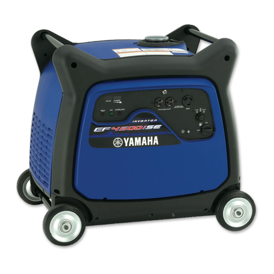
Page 126: Inverter Ef4500Ise
Yamaha Generator Theory & Diagnostics Guide INVERTER GENERATOR EF4500iSE 3-50... - Page 127 Current Model Specifications and Wiring Diagrams – EF4500iSE EF4500iSE WIRING DIAGRAM 3-51...
- Page 128 Yamaha Generator Theory & Diagnostics Guide 3-52...
- Page 129 Current Model Specifications and Wiring Diagrams – EF4500iSE (5W-30) 3-53...
- Page 130 Yamaha Generator Theory & Diagnostics Guide 3-54...
- Page 131 Current Model Specifications and Wiring Diagrams – EF4500iSE 3-55...
- Page 132 Yamaha Generator Theory & Diagnostics Guide 3-56...
- Page 133 Current Model Specifications and Wiring Diagrams – EF4500iSE 3-57...
- Page 134 Yamaha Generator Theory & Diagnostics Guide 3-58...
- Page 135 Current Model Specifications and Wiring Diagrams – EF4500iSE 3-59...
- Page 136 Yamaha Generator Theory & Diagnostics Guide 3-60...
- Page 137 Current Model Specifications and Wiring Diagrams – EF5200DE ñ ELEC ELECTRICAL COMPONENTS CONVENTIONAL GENERATOR EF5200DE ELECTRICAL ELECTRICAL COMPONENTS EF5200DE 1 Main switch 2 Economy switch 3 Oil warning light 4 Voltage meter 5 AC receptacle (125 V-20 A) 6 AC receptacle (125 V-30 A) 7 AC receptacle (125/250 V-20 A) 8 AC switch (120 V, NFB) 9 AC switch (240 V, NFB)
- Page 138 Yamaha Generator Theory & Diagnostics Guide ñ ELEC CIRCUIT DIAGRAM EF5200DE WIRING DIAGRAM PVX0090 3-62...
- Page 139 Current Model Specifications and Wiring Diagrams – EF5200DE SPEC GENERAL SPECIFICATIONS SPECIFICATIONS GENERAL SPECIFICATIONS Unit EF5200DE YG5200D ← Model code number 7VX2 Dimensions: Overall length mm (in) 894 (35.2) 670 (26.4) Overall width mm (in) 520 (20.5) 510 (20.1) Overall height mm (in) 510 (20.1) 560 (22.0)
- Page 140 Yamaha Generator Theory & Diagnostics Guide SPEC GENERAL SPECIFICATIONS Unit EF5200DE YG5200D Generator: Type Brushless, self-exciting, ← single-phase, synchro- nous generator ← Number of phase Single phase ← Number of poles ← Excitation Self magnetization ← Initial excitation Residual magnetiza- tion ←...
- Page 141 Current Model Specifications and Wiring Diagrams – EF5200DE SPEC MAINTENANCE SPECIFICATIONS MAINTENANCE SPECIFICATIONS ENGINE Unit EF5200DE YG5200D Piston: mm (in) ← Piston clearance 0.024 ~ 0.038 (0.00094 ~ 0.00150) ← <Limit> 0.100 (0.0039) ← Piston skirt ìDî 77.960 ~ 77.980 (3.0693 ~ 3.0701) ←...
- Page 142 Yamaha Generator Theory & Diagnostics Guide SPEC MAINTENANCE SPECIFICATIONS Unit EF5200DE YG5200D Cylinder head: mm (in) ← Warpage limit 0.05 (0.002) Cylinder: mm (in) ← Inside diameter ìDî 78.000 ~ 78.020 (3.0709 ~ 3.0716) ← <Limit> 78.020 (3.0716) ← Taper limit 0.05 (0.002)
- Page 143 Current Model Specifications and Wiring Diagrams – EF5200DE SPEC MAINTENANCE SPECIFICATIONS Unit EF5200DE YG5200D Valve: mm (in) Valve ← Face diameter ìAî 32.0 (1.26) ← 27.0 (1.06) ← Stem diameter ìBî 5.948 ~ 5.963 (0.2342 ~ 0.2348) ← 5.940 ~ 5.955 (0.2339 ~ 0.2344) ←...
- Page 144 Yamaha Generator Theory & Diagnostics Guide SPEC MAINTENANCE SPECIFICATIONS Unit EF5200DE YG5200D Carburetor: mm (in) ← Type/manufacture BV26-18/MIKUNI I.D. mark 7RG20 7RT30 ← Bore size ¯ 18 ← Main jet #98.8 ← Main air jet ¯ 1.6 (0.063) ← Pilot air jet ¯...
- Page 145 Current Model Specifications and Wiring Diagrams – EF5200DE SPEC MAINTENANCE SPECIFICATIONS ELECTRICAL Unit EF5200DE YG5200D Electrical: Ignition system ← Ignition timing at 3,600 r/min BTDC 25 ± 3∞ ← Primary coil resistance (Ω ± 20%) ← Secondary coil resistance (kΩ ± 10%) 11.7 ←...
- Page 146 Yamaha Generator Theory & Diagnostics Guide SPEC WIRE ROUTING DIAGRAM WIRE ROUTING DIAGRAM CONTROL BOX PANEL AND BEHIND CONTROL BOX (EF5200DE) È Condenser É Negative side is indi- cated in black. ECON. EF5200DE Ê Economy idle unit AC SW OHV ENGINE Ë...
-
Page 147: Inverter Ef6300Isde
Current Model Specifications and Wiring Diagrams – EF6300iSDE INVERTER GENERATOR EF6300iSDE 3-71... - Page 148 Yamaha Generator Theory & Diagnostics Guide EF6300iSDE WIRING DIAGRAM 3-72...
- Page 149 Current Model Specifications and Wiring Diagrams – EF6300iSDE 3-73...
- Page 150 Yamaha Generator Theory & Diagnostics Guide 3-74...
- Page 151 Current Model Specifications and Wiring Diagrams – EF6300iSDE 3-75...
- Page 152 Yamaha Generator Theory & Diagnostics Guide 3-76...
- Page 153 ELEC Current Model Specifications and Wiring Diagrams – EF6600DE ELECTRICAL COMPONENTS AND CIRCUIT DIAGRAM CONVENTIONAL GENERATOR EF6600DE ELECTRICAL ELECTRICAL COMPONENTS AND CIRCUIT DIAGRAM EF6600DE 1 Main switch 3 4 5 6 7 8 9 0 q 2 Economy idle switch 3 Oil warning light 4 Voltage meter 5 AC switch (120 V-20 A, NFB)
- Page 154 Yamaha Generator Theory & Diagnostics Guide ELEC ELECTRICAL COMPONENTS AND CIRCUIT DIAGRAM EF6600DE WIRING DIAGRAM 3-78...
- Page 155 SPEC GENERAL SPECIFICATIONS Current Model Specifications and Wiring Diagrams – EF6600DE SPECIFICATIONS GENERAL SPECIFICATIONS Unit EF6600DE YG6600D YG6600DE Model code number 7CCB Dimensions: Overall length mm (in) 894 (35.2) 670 (26.4) 894 (35.2) Overall width mm (in) 520 (20.5) 510 (20.1) 520 (20.5) Overall height mm (in) 527 (20.7)
- Page 156 Yamaha Generator Theory & Diagnostics Guide SPEC GENERAL SPECIFICATIONS Unit EF6600DE YG6600D YG6600DE Generator: Type Brushless, self-exciting, single-phase, synchronous generator Number of phase Single phase Number of poles Excitation Self magnetization Initial excitation Residual magnetization Driving method Direct connection Rated power factor...
- Page 157 Current Model Specifications and Wiring Diagrams – EF6600DE SPEC MAINTENANCE SPECIFICATIONS MAINTENANCE SPECIFICATIONS ENGINE Unit EF6600DE YG6600D YG6600DE Piston: mm (in) Piston clearance 0.015 ~ 0.029 (0.0006 ~ 0.0011) <Limit> 0.100 (0.0039) Piston skirt “D” 84.977 ~ 84.998 (3.3456 ~ 3.3464) <Limit>...
- Page 158 Yamaha Generator Theory & Diagnostics Guide SPEC MAINTENANCE SPECIFICATIONS Unit EF6600DE YG6600D YG6600DE Cylinder head: mm (in) Warpage limit 0.05 (0.0020) Cylinder: mm (in) Inside diameter “D” 85.000 ~ 85.020 (3.3465 ~ 3.3472) <Limit> 85.020 (3.3472) Taper limit 0.05 (0.0020) Warpage limit 0.05 (0.0020)
- Page 159 Current Model Specifications and Wiring Diagrams – EF6600DE SPEC MAINTENANCE SPECIFICATIONS Unit EF6600DE YG6600D YG6600DE Valve: mm (in) Valve Face diameter “A” 32.0 (1.26) 27.0 (1.06) Stem diameter “B” 5.948 ~ 5.963 (0.2342 ~ 0.2348) 5.940 ~ 5.955 (0.2339 ~ 0.2344) <Limit>...
- Page 160 Yamaha Generator Theory & Diagnostics Guide SPEC MAINTENANCE SPECIFICATIONS Unit EF6600DE YG6600D YG6600DE Valve spring: mm (in) Free length 36.2 (1.43) 36.2 (1.43) <Limit> 34.0 (1.34) 34.0 (1.34) Set length 29.0 (1.14) 29.0 (1.14) Set force 10 kg (22.0 lb) 10 kg (22.0 lb)
- Page 161 Current Model Specifications and Wiring Diagrams – EF6600DE SPEC MAINTENANCE SPECIFICATIONS Unit EF6600DE YG6600D YG6600DE Coil resistance Main coil (Br-R) (Ω ± 10%) 0.16 (Br-L) (Ω ± 10%) 0.45 Field coil (rotor assembly) (Ω ± 10%) 28 Sub coil (G-G) (Ω...
- Page 162 Yamaha Generator Theory & Diagnostics Guide SPEC WIRE ROUTING DIAGRAM WIRE ROUTING DIAGRAM CONTROL BOX PANEL AND BEHIND CONTROL BOX EF6600DE COLOR CODE å Condenser ∂ Pass the longer brown B ..Black ∫ Negative side is indi- lead through the Br ..
- Page 163 Current Model Specifications and Wiring Diagrams – EF12000DE CONTROL PANEL SERVICE DATA Clearance Data and Limits EF12000DE 3-87...
- Page 164 Yamaha Generator Theory & Diagnostics Guide EF12000DE 3-88...
- Page 165 Current Model Specifications and Wiring Diagrams – EF12000DE EF12000DE 3-89...
- Page 166 Yamaha Generator Theory & Diagnostics Guide EF12000DE 3-90...
- Page 167 Current Model Specifications and Wiring Diagrams – EF12000DE EF12000DE 3-91...
- Page 168 Yamaha Generator Theory & Diagnostics Guide EF12000DE 3-92...
- Page 169 Current Model Specifications and Wiring Diagrams – EF12000DE EF12000DE 3-93...
-
Page 170: Conventional Ef12000De
Yamaha Generator Theory & Diagnostics Guide CONVENTIONAL GENERATOR EF12000DE Control Box 3-94... - Page 171 Current Model Specifications and Wiring Diagrams – EF1200DE EF12000DE WIRING DIAGRAM 3-95...
-
Page 172: Industrial Series Generators
Yamaha Generator Theory & Diagnostics Guide ELEC – INDUSTRIAL SERIES GENERATORS ELECTRICAL COMPONENTS ELECTRICAL YG2800i ELECTRICAL COMPONENTS Control unit Engine switch Economy switch Oil warning unit AC receptacle (20 A, GFCI) AC receptacle (30 A) Ground terminal Overload warning light (Red) - Page 173 Current Model Specifications and Wiring Diagrams – YG2800i ELEC – CIRCUIT DIAGRAM YG2800i WIRING DIAGRAM 3-97...
- Page 174 SPEC GENERAL SPECIFICATIONS Yamaha Generator Theory & Diagnostics Guide SPECIFICATIONS GENERAL SPECIFICATIONS Unit YG2800i Model code number 7VU2 Dimensions: Overall length mm (in) 487 (19.2) Overall width mm (in) 395 (15.6) Overall height mm (in) 425 (16.7) Dry weight kg (lb) 29 (63.9)
- Page 175 Current Model Specifications and Wiring Diagrams – YG2800i SPEC GENERAL SPECIFICATIONS Unit YG2800i Voltage fluctuation Instantaneous Less than 20% Settling Less than 3% Settling time Less than 3 sec AC output Rated voltage Frequency Rated output Rated current 20.8 Safety device type Electronic no fuse breaker Circuit breaker (No fuse breaker) Rated engine speed...
- Page 176 Yamaha Generator Theory & Diagnostics Guide SPEC MAINTENANCE SPECIFICATIONS MAINTENANCE SPECIFICATIONS Unit YG2800i Piston: mm (in) Piston clearance 0.015 ~ 0.040 (0.00059 ~ 0.00157) <Limit> 0.100 (0.0039) Piston skirt “D” 66.0 (2.598) <Limit> 65.9 (2.594) Measuring point “H” 10.0 (0.4) Oversize 1st 66.25 (2.6083)
- Page 177 Current Model Specifications and Wiring Diagrams – YG2800i SPEC MAINTENANCE SPECIFICATIONS Unit YG2800i Crankshaft: mm (in) Big end side clearance “A” 0.20 ~ 0.60 (0.008 ~ 0.024) <Limit> 0.75 (0.029) Runout “B” <Limit> 0.04 (0.0016) Crank pin diameter “C” 28.0 (1.102) <Limit>...
- Page 178 Yamaha Generator Theory & Diagnostics Guide SPEC MAINTENANCE SPECIFICATIONS Unit YG2800i Valve guide mm (in) Guide inside diameter 5.5 (0.22) 5.5 (0.22) <Limit> 5.4 (0.21) 5.4 (0.21) Stem to guide clearance IN 0.04 ~ 0.06 (0.0016 ~ 0.0020) 0.06 ~ 0.08 (0.002 ~ 0.003) Valve clearance 0.1 (0.004)
- Page 179 Current Model Specifications and Wiring Diagrams – YG2800i SPEC MAINTENANCE SPECIFICATIONS Unit YG2800i Generator: Main coil AC voltage (3 phase) (V/r/min) 130 ~ 160/2,800 (With the throttle control motor coupler dis- connected) Sub coil AC voltage (single phase) (V/r/min) 13.5 ~ 23.0/2,800 (With the throttle control motor coupler dis- connected) Coil resistance...
- Page 180 Yamaha Generator Theory & Diagnostics Guide CONVENTIONAL GENERATOR YG4000D 3-104...
- Page 181 Current Model Specifications and Wiring Diagrams – YG4000D 3-105...
- Page 182 Yamaha Generator Theory & Diagnostics Guide YG4000D WIRING DIAGRAM 3-106...
- Page 183 Current Model Specifications and Wiring Diagrams – YG4000D 3-107...
- Page 184 Yamaha Generator Theory & Diagnostics Guide (5W-30) 3-108...
- Page 185 Current Model Specifications and Wiring Diagrams – YG4000D 3-109...
- Page 186 Yamaha Generator Theory & Diagnostics Guide 3-110...
- Page 187 Current Model Specifications and Wiring Diagrams – YG4000D 3-111...
- Page 188 Yamaha Generator Theory & Diagnostics Guide 3-112...
- Page 189 Current Model Specifications and Wiring Diagrams – YG4000D 3-113...
- Page 190 Yamaha Generator Theory & Diagnostics Guide 3-114...
- Page 191 Current Model Specifications and Wiring Diagrams – YG4000D ñ ELEC CONVENTIONAL GENERATOR YG5200D ELECTRICAL COMPONENTS YG5200D 1 Engine switch 2 Economy switch 3 Oil warning light 4 Voltage meter 5 AC switch (120 V-20 A, NFB) 6 AC receptacle (125 V-20 A, GFCI) 7 AC receptacle (125 V-20 A) 8 AC receptacle (125 V-30 A) 9 AC receptacle (125/250 V-20 A)
- Page 192 Yamaha Generator Theory & Diagnostics Guide ñ ELEC CIRCUIT DIAGRAM YG5200D WIRING DIAGRAM PVX0100 3-116...
- Page 193 SPEC Current Model Specifications and Wiring Diagrams – YG5200D GENERAL SPECIFICATIONS SPECIFICATIONS GENERAL SPECIFICATIONS Unit EF5200DE YG5200D ← Model code number 7VX2 Dimensions: Overall length mm (in) 894 (35.2) 670 (26.4) Overall width mm (in) 520 (20.5) 510 (20.1) Overall height mm (in) 510 (20.1) 560 (22.0)
- Page 194 Yamaha Generator Theory & Diagnostics Guide SPEC GENERAL SPECIFICATIONS Unit EF5200DE YG5200D Generator: Type Brushless, self-exciting, ← single-phase, synchro- nous generator ← Number of phase Single phase ← Number of poles ← Excitation Self magnetization ← Initial excitation Residual magnetiza- tion ←...
- Page 195 Current Model Specifications and Wiring Diagrams – YG5200D SPEC MAINTENANCE SPECIFICATIONS MAINTENANCE SPECIFICATIONS ENGINE Unit EF5200DE YG5200D Piston: mm (in) ← Piston clearance 0.024 ~ 0.038 (0.00094 ~ 0.00150) ← <Limit> 0.100 (0.0039) ← Piston skirt ìDî 77.960 ~ 77.980 (3.0693 ~ 3.0701) ←...
- Page 196 Yamaha Generator Theory & Diagnostics Guide SPEC MAINTENANCE SPECIFICATIONS Unit EF5200DE YG5200D Valve: mm (in) Valve ← Face diameter ìAî 32.0 (1.26) ← 27.0 (1.06) ← Stem diameter ìBî 5.948 ~ 5.963 (0.2342 ~ 0.2348) ← 5.940 ~ 5.955 (0.2339 ~ 0.2344) ←...
- Page 197 Current Model Specifications and Wiring Diagrams – YG5200D SPEC MAINTENANCE SPECIFICATIONS Unit EF5200DE YG5200D Carburetor: mm (in) ← Type/manufacture BV26-18/MIKUNI I.D. mark 7RG20 7RT30 ← Bore size ¯ 18 ← Main jet #98.8 ← Main air jet ¯ 1.6 (0.063) ←...
- Page 198 Yamaha Generator Theory & Diagnostics Guide SPEC MAINTENANCE SPECIFICATIONS ELECTRICAL Unit EF5200DE YG5200D Electrical: Ignition system ← Ignition timing at 3,600 r/min BTDC 25 ± 3∞ ← Primary coil resistance (Ω ± 20%) ← Secondary coil resistance (kΩ ± 10%) 11.7...
- Page 199 Current Model Specifications and Wiring Diagrams – YG5200D SPEC WIRE ROUTING DIAGRAM CONTROL BOX PANEL AND BEHIND CONTROL BOX (YG5200D) È Condenser É Negative side is indi- cated in black. ECON. YG5200D Ê Economy idle unit AC SW OHV ENGINE Ë...
- Page 200 7CC-28197-11 08.2.8 10:44 AM Page 10 Yamaha Generator Theory & Diagnostics Guide ELEC ELECTRICAL COMPONENTS AND CIRCUIT DIAGRAM CONVENTIONAL GENERATOR YG6600D YG6600D 1 Engine switch 3 4 5 7 8 9 0 q 2 Economy idle switch 3 Oil warning light...
- Page 201 Current Model Specifications and Wiring Diagrams – YG6600D ELEC ELECTRICAL COMPONENTS AND CIRCUIT DIAGRAM YG6600D WIRING DIAGRAM 3-125...
- Page 202 SPEC GENERAL SPECIFICATIONS Yamaha Generator Theory & Diagnostics Guide SPECIFICATIONS GENERAL SPECIFICATIONS Unit EF6600DE YG6600D YG6600DE Model code number 7CCB Dimensions: Overall length mm (in) 894 (35.2) 670 (26.4) 894 (35.2) Overall width mm (in) 520 (20.5) 510 (20.1) 520 (20.5) Overall height mm (in) 527 (20.7)
- Page 203 Current Model Specifications and Wiring Diagrams – YG6600D SPEC GENERAL SPECIFICATIONS Unit EF6600DE YG6600D YG6600DE Generator: Type Brushless, self-exciting, single-phase, synchronous generator Number of phase Single phase Number of poles Excitation Self magnetization Initial excitation Residual magnetization Driving method Direct connection Rated power factor Frequency variation Less than 5%...
- Page 204 Yamaha Generator Theory & Diagnostics Guide SPEC MAINTENANCE SPECIFICATIONS MAINTENANCE SPECIFICATIONS ENGINE Unit EF6600DE YG6600D YG6600DE Piston: mm (in) Piston clearance 0.015 ~ 0.029 (0.0006 ~ 0.0011) <Limit> 0.100 (0.0039) Piston skirt “D” 84.977 ~ 84.998 (3.3456 ~ 3.3464) <Limit>...
- Page 205 Current Model Specifications and Wiring Diagrams – YG6600D SPEC MAINTENANCE SPECIFICATIONS Unit EF6600DE YG6600D YG6600DE Cylinder head: mm (in) Warpage limit 0.05 (0.0020) Cylinder: mm (in) Inside diameter “D” 85.000 ~ 85.020 (3.3465 ~ 3.3472) <Limit> 85.020 (3.3472) Taper limit 0.05 (0.0020) Warpage limit 0.05 (0.0020)
- Page 206 Yamaha Generator Theory & Diagnostics Guide SPEC MAINTENANCE SPECIFICATIONS Unit EF6600DE YG6600D YG6600DE Valve: mm (in) Valve Face diameter “A” 32.0 (1.26) 27.0 (1.06) Stem diameter “B” 5.948 ~ 5.963 (0.2342 ~ 0.2348) 5.940 ~ 5.955 (0.2339 ~ 0.2344) <Limit>...
- Page 207 Current Model Specifications and Wiring Diagrams – YG6600D SPEC MAINTENANCE SPECIFICATIONS Unit EF6600DE YG6600D YG6600DE Valve spring: mm (in) Free length 36.2 (1.43) 36.2 (1.43) <Limit> 34.0 (1.34) 34.0 (1.34) Set length 29.0 (1.14) 29.0 (1.14) Set force 10 kg (22.0 lb) 10 kg (22.0 lb) Tilt limit 1.6 (0.06)
- Page 208 Yamaha Generator Theory & Diagnostics Guide SPEC MAINTENANCE SPECIFICATIONS Unit EF6600DE YG6600D YG6600DE Coil resistance Main coil (Br-R) (Ω ± 10%) 0.16 (Br-L) (Ω ± 10%) 0.45 Field coil (rotor assembly) (Ω ± 10%) 28 Sub coil (G-G) (Ω ± 10%) 0.35 Exciter stator coil (Ω...
- Page 209 Current Model Specifications and Wiring Diagrams – YG6600D SPEC WIRE ROUTING DIAGRAM YG6600D COLOR CODE å Condenser ç Economy idle unit ∂ Pass the longer brown B ..Black ∫ Negative side is indi- lead through the econ- Br ..Brown cated in black.
- Page 210 Yamaha Generator Theory & Diagnostics Guide SPEC WIRE ROUTING DIAGRAM YG6600DE COLOR CODE å Condenser ç Economy idle unit ∂ Pass the longer brown B ..Black ∫ Negative side is indi- lead through the econ- Br ..Brown cated in black.
- Page 211 ELEC – ELECTRICAL COMPONENTS AND CIRCUIT DIAGRAM Current Model Specifications and Wiring Diagrams – YG6600DE YG6600DE 1 Start switch 2 Economy switch 3 Engine switch 4 Oil warning light 5 Voltage meter 6 AC switch (120 V-20 A, NFB) 7 AC receptacle (125 V-20 A, GFCI) 8 AC receptacle (125 V-20 A) 9 AC receptacle (125 V-30 A) 0 AC receptacle (125/250 V-30 A)
- Page 212 Yamaha Generator Theory & Diagnostics Guide ELEC – ELECTRICAL COMPONENTS AND CIRCUIT DIAGRAM YG6600DE WIRING DIAGRAM PWV0420 3-136...
- Page 213 SPEC GENERAL SPECIFICATIONS Current Model Specifications and Wiring Diagrams – YG6600DE EF6600DE YG6600D YG6600DE 7WW2 894 (35.2) 670 (26.4) 894 (35.2) 520 (20.5) 510 (20.1) 520 (20.5) 510 (20.1) 560 (22.0) 90 (198.4) 85 (187.4) 92 (202.8) 4-stroke OHV forced air cooled 0.357 (357) 85.0 ×...
- Page 214 Yamaha Generator Theory & Diagnostics Guide SPEC GENERAL SPECIFICATIONS EF6600DE YG6600D YG6600DE Brushless, self-exciting, single-phase, synchronous generator Single phase Self magnetization Residual magnetization Direct connection Less than 5% Less than 10% 120/240 50.0/25.0 NFB (No fuse breaker) 3,600 2,350 More than 10...
- Page 215 SPEC MAINTENANCE SPECIFICATIONS Current Model Specifications and Wiring Diagrams – YG6600DE EF6600DE YG6600D YG6600DE 0.015 ~ 0.029 (0.0006 ~ 0.0011) 0.100 (0.0039) 84.977 ~ 84.998 (3.3455 ~ 3.3464) 84.900 (3.3425) 10.0 (0.4) 85.25 (3.3563) 85.50 (3.3661) 20.000 (0.7874) 20.020 (0.7882) 19.995 ~ 20.000 (0.7872 ~ 0.7874) 19.950 (0.7854) Barrel face...
- Page 216 Yamaha Generator Theory & Diagnostics Guide SPEC MAINTENANCE SPECIFICATIONS EF6600DE YG6600D YG6600DE 0.05 (0.002) 85.000 ~ 85.020 (3.3465 ~ 3.3472) 85.020 (3.3472) 0.05 (0.002) 0.05 (0.002) 0.20 ~ 0.65 (0.008 ~ 0.026) 0.8 (0.032) 0.04 (0.0016) 35.969 ~ 35.984 (1.4161 ~ 1.4167) 35.9 (1.4134)
- Page 217 Current Model Specifications and Wiring Diagrams – YG6600DE SPEC MAINTENANCE SPECIFICATIONS EF6600DE YG6600D YG6600DE 32.0 (1.26) 27.0 (1.06) 5.948 ~ 5.963 (0.2342 ~ 0.2348) 5.940 ~ 5.955 (0.2339 ~ 0.2344) 5.9 (0.23) 5.9 (0.23) 88.1 (3.47) 87.9 (3.46) 0.7 ~ 0.9 (0.0276 ~ 0.0354) 0.7 ~ 0.9 (0.0276 ~ 0.0354) 1.4 (0.551) 1.4 (0.551)
- Page 218 ©2009 Yamaha Motor Corporation, U.S.A. Printed in U.S.A. LIT-BKTEC-GN-01...