Yamaha EF2000iS - Inverter Generator Owner's Manual
Owners manual
Hide thumbs
Also See for EF2000iS - Inverter Generator:
- Owner's manual (526 pages) ,
- Service manual (313 pages) ,
- Owner's manual (276 pages)

Related Manuals for Yamaha EF2000iS - Inverter Generator


Summary of Contents for Yamaha EF2000iS - Inverter Generator
- Page 1 Generator OWNER’S MANUAL Read this manual carefully before operating this machine. EF2000iS LIT-19626-01-53 7DK-28199-10...
- Page 2 Read this manual carefully befor operating this machine.This manual should stay with this machine if it is sold.
- Page 3 AE00002 INTRODUCTION Congratulations on your purchase of your new Yamaha. This manual will provide you with a good basic understanding of the operation and main- tenance of this machine. If you have any questions regarding the operation or maintenance of your machine, please consult a Yamaha dealer.
- Page 4 OPERATING THE MACHINE. A WARNING indicates a hazardous situ- ation which, if not avoided, could result in death or serious injury. 9 Yamaha continually seeks advance- NOTICE ments in product design and quality. Therefore, while this manual contains A NOTICE indicates special precau-...
-
Page 5: Table Of Contents
AE00041 CONTENTS SAFETY INFORMATION......1 Application range........20 EXHAUST FUMES ARE PERIODIC MAINTENANCE ....21 POISONOUS........1 Maintenance chart......21 FUEL IS HIGHLY FLAMMABLE AND Spark plug inspection ......23 POISONOUS........1 Carburetor adjustment......24 ENGINE AND MUFFLER MAY BE Engine oil replacement.......24 HOT ............1 Air filter ..........26 ELECTRIC SHOCK PREVENTION ..2 Muffler screen and spark arrester ..27 CONNECTION NOTES ......3... -
Page 6: Safety Information
AE00071 SAFETY INFORMATION AE00072 EXHAUST FUMES ARE POISONOUS 9 Never operate the engine in a closed area or it may 7DK-001 cause unconsciousness and death within a short time. Operate the engine in a well ventilated area. AE00075 FUEL IS HIGHLY FLAMMABLE AND POISONOUS 9 Always turn off the engine when refuelling. -
Page 7: Electric Shock Prevention
9 Keep the machine at least 1 m (3 ft) from buildings or other equipment, or the engine may overheat. a 1 m (3 ft) 7DK-007 9 Do not operate the engine with a dust cover or other objects covering it. 9 When covering the generator, be sure to do so only after the engine and muffler have completely cooled down. -
Page 8: Connection Notes
9 Connect the ground lead of the machine to the ground (Earth) terminal 1 and connect the end to the ground electrode buried in the ground. 7DK-011 AE00088 CONNECTION NOTES 9 Avoid connecting the generator to commercial power outlet. 9 Avoid connecting the generator in parallel with any other generator. -
Page 9: Location Of Important Labels
AE00062 LOCATION OF IMPORTANT LABELS Please read the following labels carefully before oper- ating this machine. Maintain or replace safety and instruction labels, as necessary. 7DK-013 7DK-014 DANGER Using a generator indoors CAN KILL YOU IN MINUTES. Generator exhaust contains carbon monoxide. This is a poison you cannot see or smell. - Page 10 7WL-28176-10 Specified plug:BPR6HS(NGK) Important Emissions Information The air index of this engine is 3 YAMAHA MOTOR POWERED PRODUCTS CO.,LTD. (California only) This engine meets **** California exhaust and evaporative emission regulations for small off-road engines. This engine conforms to Phase 2 U.S.EPA regulations for...
-
Page 11: Description
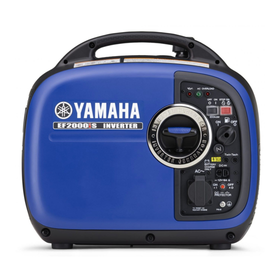
DESCRIPTION 1 Carrying handle 2 Fuel tank cap air vent knob 3 Fuel tank cap 4 Recoil starter 5 Fuel gauge 6 Muffler 7 Oil filler cap 7DK-015 7DK-016 AE00103 Control panel 1 Oil warning light 2 AC pilot light 3 Overload indicator light 4 Economy control switch (Black) -
Page 12: Control Function
AE00101 CONTROL FUNCTION AE00121 Engine switch The engine switch controls the ignition system. 7 “ON” 7DK-018 Ignition circuit is switched on. The engine can be started. 2 5 “STOP” Ignition circuit is switched off. The engine will not run. AE00111 Oil warning light (Red) When the oil level falls below the lower level, the oil warning light comes on and then the engine stops auto-... -
Page 13: Economy Control Switch
Reduce the load of the connected electric device below the specified rated output of the generator if the DC protector turns off. If the DC protector turns off again, stop using the device immediately and consult a Yamaha dealer. AE00142 Economy control switch 1 I “ON”... -
Page 14: Overload Indicator Light (Red)
AE01087 Overload indicator light (Red) The overload indicator light 1 comes on when an over- load of a connected electrical device is detected, the inverter control unit overheats, or the AC output voltage rises. Then, the AC protector will trip, stopping power generation in order to protect the generator and any 7DK-021 connected electric devices. -
Page 15: Fuel Tank Cap Air Vent Knob
25.0 A.) The handling, operation procedure and the notes on usage are described in the PARALLEL RUNNING KIT OWNER’S MANUAL included in the Parallel Running Kit. Consult a Yamaha dealer for this Parallel Running Kit. – 10 –... -
Page 16: Preparation
7DK-028 4 “F” Full 5 “E” Empty Your Yamaha engine has been designed to use regular unleaded gasoline with a pump octane number ((R + M)/2) of 86 or higher, or research octane number of 91 or higher. 7DK-093 – 11 –... -
Page 17: Engine Oil
AE00222 Engine oil NOTICE The generator has been shipped without engine oil. Do not start the engine till fill with the sufficient engine oil. 1. Place the generator on a level surface. 2. Remove the screws 1, and then remove the cover 7DK-030 3. -
Page 18: Pre-Operation Check
9 Check oil level in engine. 9 If necessary, add recommended oil to specified level. 9 Check generator for oil leakage. The point where abnormality was recognized by 9 Check operation. 9 If necessary, consult a Yamaha dealer. – 13 –... -
Page 19: Operation
AE00846 OPERATION WARNING 9 Never operate the engine in a closed area or it may cause unconsciousness and death within 7DK-047 a short time. Operate the engine in a well venti- lated area. 9 Before starting the engine, do not connect any electric devices. - Page 20 5. Pull the choke knob 1 fully out. 1 Choke knob The choke is not required to start a warm engine. Push the choke knob in to the original position. 7DK-040 6. Pull slowly on the recoil starter until it is engaged, then pull it briskly.
-
Page 21: Stopping The Engine
AE01025 Stopping the engine Turn off any electric devices. 7DK-034 1. Turn the economy control switch (Black) to “OFF” 1 3 “OFF” 2. Disconnect any electric devices. 7DK-047 3. Turn the engine switch (Red) to “STOP” 1. 1 5 “STOP” 7DK-044 4. -
Page 22: Connection
AE00839 Connection Alternating Current (AC) WARNING Be sure any electric devices are turned off before plugging them in. NOTICE 9 Be sure all electric devices including the lines and plug connections are in good condition before connection to the generator. 9 Be sure the total load is within generator rated output. -
Page 23: Battery Charging
7DK-052 To restart charging the battery, turn the DC pro- tector on by pressing its button to “ON” 1. If the DC protector turns off again, stop charging the battery immediately and consult a Yamaha dealer. 1 “ON” 2 “OFF”... - Page 24 9 Follow instructions in the owner’s manual for the battery to determine the end of battery charging. 9 Measure the specific gravity of electrolyte to deter- mine if the battery is fully charged. At full charge, the electrolyte specific gravity is between 1.26 and 1.28.
-
Page 25: Application Range
AE00812 Application range When using the generator, make sure the total load is within rated output of a generator. Otherwise, generator damage may occur. 0.4–0.75 Power factor 0.8–0.95 (Efficiency 0.85) Rated voltage EF2000iS –1,600W –1,280W –544W Rated current 9 “–” means below. 9 Application wattage indicates when each device is used by itself. -
Page 26: Periodic Maintenance
The most impor- tant points of generator inspection, adjustment, and lubrication are explained on the fol- lowing pages. WARNING If you are not familiar with maintenance work, have a Yamaha dealer do it for you. AE00403 Maintenance chart WARNING Stop the engine before starting maintenance work. - Page 27 *1·····Initial replacement of the engine oil is after one month or 20 hours of operation. *2·····The air filter element needs to be cleaned more frequently when using in unusually wet or dusty areas. #····· Since these items require special tools, data and technical skills, have a Yamaha dealer perform the service. – 22 –...
-
Page 28: Spark Plug Inspection
Spark plug inspection The spark plug is important engine components, which should be checked periodically. 1. Remove the screws 1, and then remove the cover 7DK-030 2. Remove the spark plug cap 3 and cap 4, and insert the tool 5 through the hole from the outside of the cover. -
Page 29: Carburetor Adjustment
8. Install the cover and tighten the screws. AE00431 Carburetor adjustment The carburetor is a vital part of the engine. Adjusting should be left to a Yamaha dealer with the professional knowledge, specialized data, and equipment to do so properly. AE00412... - Page 30 4. Place an oil pan under the engine. Tilt the genera- tor to drain the oil completely. 5. Replace the generator on a level surface. NOTICE Do not tilt the generator when adding engine oil. 7DK-055 This could result in overfilling and damage to the engine.
-
Page 31: Air Filter
AE01084 Air filter 1. Remove the screws 1, and then remove the cover 7DK-030 2. Remove the screw 1 and then remove the air filter case cover 2. 7DK-061 3. Remove the foam element 1. 4. Wash the foam element in solvent and dry it. 5. -
Page 32: Muffler Screen And Spark Arrester
AE01075 Muffler screen and spark arrester WARNING The engine and muffler will be very hot after the engine has been run. 7DK-026 Avoid touching the engine and muffler while they are still hot with any part of your body or clothing during inspection or repair. - Page 33 3. Remove the carbon deposits on the muffler screen and spark arrester using a wire brush. NOTICE When cleaning, use the wire brush lightly to avoid damaging or scratching of the muffler screen and 711-075 spark arrester. 4. Check the muffler screen and spark arrester. Replace them if damaged.
-
Page 34: Fuel Tank Filter
AE00471 Fuel tank filter WARNING Never use the gasoline while smoking or in the vicinity of an open flame. 1. Remove the fuel tank cap and filter 1. 2. Clean the filter with gasoline. If damaged, replace it. 3. Wipe the filter and install it. 4. -
Page 35: Storage
AE00601 STORAGE Long term storage of your machine will require some preventive procedures to guard against deterioration. AE01056 Drain the fuel 1. Turn the engine switch to “STOP” 1. 2. Remove the fuel tank cap. Extract the fuel from the fuel tank into an approved gasoline container using a commercially available handsiphon. - Page 36 6. Remove the screws 1, and then remove the cover 7DK-030 7. Drain the fuel from the carburetor by loosening the drain screw 3 on the carburetor float chamber. 8. Turn the engine switch to “OFF”. 9. Turn the fuel cock knob to “OFF”. 10.
-
Page 37: Engine
Engine Perform the following steps to protect the cylinder, pis- ton ring, etc. from corrosion. 1. Remove the spark plug, pour about one table- spoon of SAE 10W-30 or 20W-40 motor oil into the spark plug hole and reinstall the spark plug. Recoil start the engine by turning over several times (with ignition off) to coat the cylinder walls with oil. -
Page 38: Troubleshooting
AE00512 TROUBLESHOOTING Engine won’t start 1. Fuel systems No fuel supplied to combustion chamber. 2 No fuel in tank ..Supply fuel. 7DK-091 2 Fuel in tank ..Fuel tank cap air vent knob and fuel cock knob to “ON” 1. 2 Clogged fuel line .. -
Page 39: Generator Won't Produce Power
2 Engine switch to “ON” 1 and pull the recoil starter. Poor spark 2 Spark plug dirty with carbon or wet ..Remove car- bon or wipe spark plug dry. 2 Faulty ignition system ..Consult a Yamaha dealer. 7DK-039 7DK-041 791-001d AE00515 Generator won’t produce power... - Page 40 Replace or Clean the spark Adjust Gap. plug. Dose not spark Check the following Clean or Replace; Consult O Clogged 9 Fuel line clogging Yamaha dealer. 9 Air cleaner element Consult a Yamaha dealer. clogging. – 35 –...
-
Page 41: Specifications
AE00701 SPECIFICATIONS AE00702 Dimensions Unit EF2000iS Overall Length mm (in) 490 (13.3) Overall Width mm (in) 280 (11.0) Overall Height mm (in) 455 (17.9) Dry Weight kg (lb) 20 (44) AE00704 Engine Unit EF2000iS Type Air cooled 4-stroke gasoline OHV Cylinder Arrangement Inclined, 1 cylinder Displacement... -
Page 42: Consumer Information
Record your Primary I.D., and serial num- MODEL bers in the spaces provided, to assist you in ordering spare parts from a Yamaha dealer. Also record and keep these I.D. numbers in PRI-I.D. a separate place in case your machine is CODE SERIAL No. -
Page 43: Limited Warranty (Ef- And Edl-Series)
FOR A PARTICULAR PURPOSE WHICH EXCEED authorized Yamaha consumer generator dealer will, THE OBLIGATIONS AND TIME LIMITS STATED IN free of charge, repair or replace, at Yamaha’s THIS WARRANTY ARE HEREBY DISCLAIMED BY option, any part adjudged defective by Yamaha due YAMAHA MOTOR CORPORATION, U.S.A. - Page 44 Corporation, U.S.A. by the selling dealer at the time specified in the Owner’s Manual? of your purchase. If you should move after you have A. No. The warranty on a new Yamaha cannot be purchased your new generator, please advise us of “voided” or “cancelled.”...
-
Page 45: Exhaust Emission Control System And Components
ROAD ENGINES. The acronyms conform to the latest version of the SAE’s recommended practice docu- ment J1930, “Diagnostic Acronyms, Terms, and Definitions For Electrical/Electronic System”. It is recommended that these items be serviced by a Yamaha dealer. – 40 –... -
Page 46: Wiring Diagram
AE00751 WIRING DIAGRAM 7DK-10 1 Sub coil p Oil level gauge Color code 2 DC coil Black 3 Main coil Brown 4 DC rectifier Green 5 DC protector (breaker) Gray 6 Twin Tech (parallel Blue running terminal) Orange 7 DC receptacle 8 AC pilot light White 9 AC receptacle... - Page 48 PRINTED IN JAPAN 2009.01-1.0×1 ! PRINTED ON RECYCLED PAPER...