Grizzly G1035 Instruction Manual
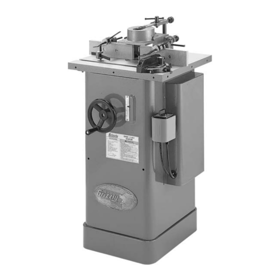
1 1/2 hp heavy-duty shaper
Hide thumbs
Also See for G1035:
- Owner's manual (64 pages) ,
- Parts list (10 pages) ,
- User manual (1 page)
Table of Contents
Advertisement
Quick Links
Advertisement
Table of Contents

Related Manuals for Grizzly G1035


Summary of Contents for Grizzly G1035
-
Page 1: Instruction Manual
MODEL G1035 INSTRUCTION MANUAL COPYRIGHT © 1990 BY GRIZZLY INDUSTRIAL, INC. WARNING: NO PORTION OF THIS MANUAL MAY BE REPRODUCED IN ANY SHAPE OR FORM WITHOUT THE WRITTEN APPROVAL OF GRIZZLY INDUSTRIAL, INC. #BL4708 REVISED JUNE, 2006. PRINTED IN TAIWAN... - Page 2 ���� ������ �������� �������� ������ ������������ �� ��� ������ ������ ���������� ����������� ��� ������� �� ���� ������������������ ������� �� ����� ���������� ��� ������ ��� ������������ ����� �� ���� ������ ��� ������ �� ������� �������� ������� ��������� ����������� ������������� �� ������ ���...
-
Page 3: Table Of Contents
Table of Contents SECTION 1: SAFETY........................3 Additional Safety Instructions for Shapers ................. 5 SECTION 2: INTRODUCTION ......................6 Commentary ..........................6 SECTION 3: CIRCUIT REQUIREMENTS ..................7 110V Operation .......................... 7 220V Operation .......................... 7 Grounding ........................... 8 Extension Cords ......................... 8 Wiring Diagram .......................... - Page 4 Pulley Alignment ........................34 V-Belt Tension .......................... 35 Truing The Fence ........................35 Adjusting Spindle Gibs ......................36 G1035 Wiring Diagram 110V ....................37 G1035 Wiring Diagram 220V ....................38 SECTION 10: CLOSURE ....................... 39 G1035 Data Sheet ........................40 Stand Assembly Parts Breakdown ...................
-
Page 5: Section 1: Safety
����� ������� ���������� ������������ ���� ������������������������������������������ ������������������� �� ����� ������� ��������� ���� �� ������ ���� � ����� �������� ������ �� ����� ��� ��������� �� ���������� ���� ��������� ����� �� �������� ������������������ ��������� ���� �������� ������ ������������������������������������ ���������������������������������������� ���������������������������������������� G1035 Heavy-Duty Shaper... - Page 6 �� ���������� ��� ���� ������������ ���� ����������������������������������������� ����� ��� ������� ���� ��������� ����������� � �������������������������������������������� ������������������������������������������ ������������������������������������� ��������������������������������������������� ��� ���� ���� ������ ��� �� ����� �������� ��� ���� ������� ����� �� ����������� ��� ���� ��������� ������ ��������������������������������� ����� ���������� G1035 Heavy-Duty Shaper...
-
Page 7: Additional Safety Instructions For Shapers
No list of safety guidelines can be complete. Like all machines there is danger associ- ated with the Model G1035. Accidents are Every shop environment is different. Always consider safety first, as it applies to your frequently caused by lack of familiarity or failure to pay attention. -
Page 8: Section 2: Introduction
SECTION 2: INTRODUCTION Commentary We are also pleased to provide this manual with the Model G1035. It was written to guide you through assembly, review safety considerations, and cover general operating procedures. It repre- sents our effort to produce the best documenta- tion possible. -
Page 9: Section 3: Circuit Requirements
SECTION 3: CIRCUIT REQUIREMENTS 110V Operation 220V Operation The Model G1035 Shaper motor is prewired to The motor supplied with the Model G1035 can operate at 110V. A plug is not included with this be operated at either 110V or 220V. The motor machine. -
Page 10: Grounding
Wiring Diagram The Model G1035 comes prewired for 110 volt operation. Wiring diagrams for 110V and 220V operation are provided at the back of this man- ual. -
Page 11: Section 4: Identification
Figure 3 to identify the shaper controls and features. A. Cutterhead Guard B. Hold Down C. Fence D. Spindle E. Elevation Handwheel Spindle Height Scale G. ON/OFF Reversing Switch H. Miter Gauge Figure 3. Model G1035 controls and features. Motor Cover G1035 Heavy-Duty Shaper... -
Page 12: Section 5: Set Up
After all the parts have been removed from the carton, you should have: Shaper Unit ............1 The Model G1035 Heavy-Duty Shaper is shipped from the manufacturer in a carefully packed Box 1: carton. If you discover the machine is damaged •... -
Page 13: Hardware Recognition Chart
Washer ⁄ ⁄ ⁄ ⁄ 10mm ⁄ ⁄ 15mm ⁄ ⁄ ⁄ 20mm ⁄ ⁄ 25mm 30mm ⁄ 10mm 35mm ⁄ 40mm ⁄ 45mm ⁄ 12mm 50mm 55mm ⁄ 60mm ⁄ 65mm ⁄ 70mm 16mm 75mm -11- G1035 Heavy-Duty Shaper... -
Page 14: Clean Up
Most shop floors vent cleaner or citrus-based degreaser such as will be adequate for the weight of this machine; Grizzly’s G7895 Degreaser. To clean thoroughly, however, some floors may require additional sup- some parts may need to be removed. For opti- port. -
Page 15: Beginning Assembly
Beginning Assembly Motor Brace The Model G1035 is equipped with motor braces to prevent damage to the motor during shipping. These braces are intended to be removed before Disconnect power from operation. the machine when per- forming any maintenance, To remove the motor braces: assembly or adjustments. -
Page 16: Switch
Figure 6. Sliding switch between motor and motor mounting bracket. Slide the power and swtich cords between the motor and cabinet (Figure 7) and remove Figure 9. Securing grommet to motor cover. the switch and grommet from the cabinet. -14- G1035 Heavy-Duty Shaper... -
Page 17: Handwheel
Mount the FWD/REV switch to the cabinet, as shown in Figure 10, using the screws already mounted in the cabinet at that location. Spindle The Model G1035 comes with ⁄ " & ⁄ " spindles. Each spindle is sized to work efficiently cut- ters and spacers that have ⁄... -
Page 18: Table Inserts
Table Inserts create an unsafe condition and possible injury to the operator. The Model G1035 is supplied with two inserts that Thread the drawbar nut, tapered side up, onto give you three possible diameter openings in the the bottom of the drawbar. See Figure 14. -
Page 19: Fence Assembly
Fence Assembly To install the fence assembly: Attach the fence assembly to the table, as shown in Figure 17, with the cap screws and washers already mounted to the table. Figure 17. Fence assembly attachment location. -17- G1035 Heavy-Duty Shaper... -
Page 20: Hold-Downs
Extension Bar Main Guard Lock Handle Shaft Shaft Mount Bracket Figure 18. Guard assembly. -18- G1035 Heavy-Duty Shaper... -
Page 21: Dust Collection
Figure 21. Use hold-downs from both sides. -19- G1035 Heavy-Duty Shaper... -
Page 22: Section 6: Operations
If the shaper seems to be running correctly, check the directional switch. The spindle should be rotating in a counterclockwise direction when the switch is in the FORWARD position. Run the Model G1035 for a short time to ensure that the Always wear dust... -
Page 23: Rotation
Rotation Speed Changes Your shaper is equipped with a FORWARD/ The Model G1035 Shaper is equipped with a spe- REVERSE switch. See Figure 23. In many cial high speed V-belt. It is designed to withstand instances, it will be necessary to flip the cutter the vibration and sudden shock loads associated over and reverse cutter rotation. -
Page 24: Cutter Installation
Tighten the nuts while holding the spindle stationary. Use a wrench on the notches at the top of the spindle for leverage as shown in Figure 26. Figure 27. Spindle lock knob. Replace the safety guard. -22- G1035 Heavy-Duty Shaper... -
Page 25: Fence Adjustment
You must use a box guard (Figure 28) while shap- ing workpieces to provide additional protection for your hands. However, Grizzly Industrial is not able to provide a box guard with your shaper due to variables beyond our control, including the dimen- sions and orientation of your workpiece. -
Page 26: Straight Shaping
OFF. When the cutter comes to a complete stop, adjust the outfeed fence to support the new profiled edge. See Figure 32. Figure 31. Fence adjustments. Figure 32. Support workpiece as it is fed. -24- G1035 Heavy-Duty Shaper... - Page 27 Run a test piece through the shaper. See is ON merely by listening. It is necessary Figure 33. to make certain that this machine is OFF before attempting any setup or adjustments. Serious personal injury could occur. Figure 33. Partial feed fence adjustment. -25- G1035 Heavy-Duty Shaper...
-
Page 28: Shaping Small Stock
Failure to follow this warning may lead to severe personal injury. Fence Mount Holes for Fasteners Figure 35. Example of a zero clearance fence. -26- G1035 Heavy-Duty Shaper... -
Page 29: Rub Collars
Figure 39. Figure 38. Using rub collar between cutters. ALWAYS FEED AGAINST THE ROTATION OF THE CUTTER. -27- G1035 Heavy-Duty Shaper... - Page 30 Figure 42. Use starting pin substitute when Figure 40. Inserting starting pin. needed. (Guard removed for clarity.) Use some type of hold-down fixture and guard when doing freehand work. See Figure 41. -28- G1035 Heavy-Duty Shaper...
-
Page 31: Pattern Work
The workpiece must be fixed securely to the jig. Figure 43. Perform pattern work with rub collar. -29- G1035 Heavy-Duty Shaper... -
Page 32: Section 7: Accessories
Use them below, in between or above cutters. Figure 46. G4840 Dust Hood. G1706—Cast Iron Wing for Model G1035 Cast Iron Wing (20" x 10") for use with our G1035 ⁄ HP Shaper. Figure 44. G3362 Rub Collar Set. - Page 33 H1300 H1298 G7984 Figure 48. G3030 Shaper Handbook. H0736 H2347 G1705—Bit Spindle Router bit spindle for use with our G1035 1 ⁄ Figure 50. Our most popular safety glasses. Shaper. For ⁄ ” and ⁄ ” shank bits.
-
Page 34: Section 8: Maintenance
Disconnect power from the machine when per- The table and other non-painted surfaces on the forming any maintenance. Model G1035 should be protected against rust Failure to do this may and pitting. Wiping the table clean after every result in serious personal use ensures that moisture from wood dust isn’t... -
Page 35: Spindle Bearings
The bearing housing will drop down. If you need to spread the casting more, use a screwdriver. The spindle bearing housing equipped with the Model G1035 features factory-sealed bearings. A sealed bearing requires no lubrication during its lifetime. Should a bearing fail, your shaper will probably develop a noticeable rumble, which will increase when the machine is put under load. -
Page 36: Section 9: Service Adjustments
Check the alignment with a straightedge. If tion with a dead blow hammer. the pulleys are in alignment, the straightedge should touch two sides of each pulley evenly. See Figure 52. Figure 52. Checking pulley alignment. -34- G1035 Heavy-Duty Shaper... -
Page 37: V-Belt Tension
Make sure the screws are countersunk deep tension, and check pulleys. enough so the workpiece will not come in contact with the heads of the screws. Repeat Steps 2-3 until tension is correct, and pulleys are aligned. -35- G1035 Heavy-Duty Shaper... -
Page 38: Adjusting Spindle Gibs
Failure to do so may cause disappointing results. DO NOT over-tighten the gib. Over-tightening will restrict spindle movement. Raise and lower the spindle to check for free movement. -36- G1035 Heavy-Duty Shaper... -
Page 39: G1035 Wiring Diagram 110V
G1035 Wiring Diagram 110V ����������������������������������������������� ���������������������������������������������������������� ����������� ���������� ��������� ����������� ������� ����� ���� � � ���� ���� ���������� ��������� ����������� ��������� ���������� ��������� ������������������ � � � � � � �������� ������� ������������������������� ������� ������������������������� ���������������������� ������������������������� ��������������� ������������������������� ����... -
Page 40: G1035 Wiring Diagram 220V
G1035 Wiring Diagram 220V ����������������������������������������������� ���������������������������������������������������������� ����������� ���������� ����������� ��������� ���� ������� ���� ���� � ����� � ���������� ��������� ����������� ���������� ����������� ���������� ���������������������������������� ������������������������������� ������������������ � � � � � � �������� ������� ������������������������� ������� ������������������������� ���������������������� ������������������������� ���������������... -
Page 41: Section 10: Closure
3: Introduction. The specifications, drawings, and photographs illustrated in this manual represent The Model G1035 was specifically designed the Model G1035 as supplied when the manual for shaping. DO NOT modify and/or use this was prepared. However, due to Grizzly’s policy machine for any other purpose. -
Page 42: G1035 Data Sheet
G1035 Data Sheet MACHINE DATA SHEET Customer Service #: (570) 326-3806 • To Order Call: (800) 523-4777 • Fax #: (800) 438-5901 GRIZZLY MODEL G1035 1 ⁄ HP SHAPER Design Type ..................... Floor Model Overall Dimensions: Table ......................20 ⁄ " x18"... -
Page 43: Stand Assembly Parts Breakdown
Stand Assembly Parts Breakdown -41- G1035 Heavy-Duty Shaper... -
Page 44: Stand Assembly Parts List
P1035019 MAIN FENCE HOUSING P1026041 SCALE 20A PSS05 SETSCREW ⁄ " - 18 x ⁄ " P1035041 NAMEPLATE LABEL P1035021 KNURLED KNOB WARNING LABEL 41A P1035041A P1035022 ADJ. SCREW BRACKET P1035042 GROMMET PTLW01 EXT TOOTH WASHER #10 -42- G1035 Heavy-Duty Shaper... -
Page 45: Motor And Handwheel Parts Breakdown
Motor and Handwheel Parts Breakdown 144A 141A 131A 133 128A 147A 127A 129A 115A 107A 123-1 -43- G1035 Heavy-Duty Shaper... -
Page 46: Motor And Handwheel Parts List
KEY 5 x 5 x 15mm PW02 FLAT WASHER ⁄ " P1035123 ELEVATION LEADSCREW PLW04 LOCK WASHER ⁄ " 123-1 P51102 BEARING 51102 PSS02 SETSCREW ⁄ " - 18 x ⁄ " P1035126 SPINDLE SLIDE 127A PW07 FLAT WASHER ⁄ " -44- G1035 Heavy-Duty Shaper... -
Page 47: Spindle Parts Breakdown
Spindle Parts Breakdown 201D 201C 201B 201A 218A REPLACEMENT SPINDLE CARTRIDGES P/N 204 SUPPLIED WITH PIN P/N 203 -45- G1035 Heavy-Duty Shaper... -
Page 48: Spindle Parts List
" x ⁄ " SPACER P1035213 SLEEVE P1035229 SPACER, LONG P1035214 BEARING HOUSING P1026223A ⁄ " SPINDLE WASHER P1035215 DRAW BAR P1026224A ⁄ " SPINDLE WASHER PR13M SNAP RING 65mm P1026226 SPINDLE WRENCH SET P1035217 STEP PULLEY -46- G1035 Heavy-Duty Shaper... -
Page 49: Safety Guard Parts Breakdown And List
G1035 GUARD ASSEMBLY Safety Guard Parts Breakdown and List PART # DESCRIPTION PART # DESCRIPTION 409 P1026309 SHAFT 401 PSS02 SETSCREW ⁄ " - 18 x ⁄ " 410 P1035410 HANDLE ASY. W/#411, 412 402 P1035402 SHAFT MOUNT 413 PN05 HEX NUT ⁄... -
Page 50: Fence Parts Breakdown And List
Fence Parts Breakdown and List PART # DESCRIPTION 501 P1035501 HOLD-DOWN BAR 502 P1035502 HOLD-DOWN 503 P1035503 BRACKET, HOLD-DOWN 504 PSS03 SETSCREW ⁄ " - 20 x ⁄ " -48- G1035 Heavy-Duty Shaper... -
Page 51: Miter Gauge Parts Breakdown And List
MITER BAR 614 PRP54M ROLL PIN 1.5 X 3MM PN07 HEX NUT 10-24 615 P1023SL415 MITER HINGE PIN 608A PSS32 SETSCREW 10-24 X ⁄ " 616 P1035616 COMPLETE MITER GAUGE 609A PSS29 SETSCREW 10-24 X ⁄ " -49- G1035 Heavy-Duty Shaper... -
Page 52: Warranty And Returns
WARRANTY AND RETURNS Grizzly Imports, Inc. warrants every product it sells for a period of 1 year to the original purchaser from the date of purchase. This warranty does not apply to defects due directly or indirectly to misuse, abuse, negligence, accidents, repairs or alterations or lack of maintenance. - Page 53 �������� ���� ���������������������������������������������������������������������������������� � ������������������������������������������������������������������������������������ ����� ����������������������� ������ � ������������������������ ���� ��������������������� ���������������������������� ������ ������������������������ ���������� � ���������������� ���������������������������� ������������������������������� ��������������������������� ��� ��������� ����������� �� ����� �� � ��������� ������ �� ���� �� ���� ��� ��������� �������� �� ���� �� ������� ������...
- Page 54 ���������������������� ����� ����� ���� ������� ����������� ���� ���� ��� ���� ����������� �� ���������� ���������������������� ����������������������������������� ����������������������������������� ������������������������������������� �������������������������������������� ��������������������������������������...
- Page 56 ��� ������ ��� ���� ���� ������� � �������� ������ ��� � ����� ������ � ����� ��� ������� ����� ��� �������� ��� ������� �� ��� �������� ������� � � ������ �������� � ������ ������� ������ �� ����� � ������ �������� ������ ��� ���� ����...