Grizzly G1035 Owner's Manual
11/2 hp shaper
Hide thumbs
Also See for G1035:
- Owner's manual (64 pages) ,
- Instruction manual (56 pages) ,
- Parts list (10 pages)
Table of Contents
Advertisement
Quick Links
MODEL G1035/G1035P
1
⁄
HP SHAPER
1
2
OWNER'S MANUAL
(For models manufactured since 04/10)
177335
COPYRIGHT © 1990 BY GRIZZLY INDUSTRIAL, INC. REVISED DECEMBER, 2017 (HE)
WARNING: NO PORTION OF THIS MANUAL MAY BE REPRODUCED IN ANY SHAPE
OR FORM WITHOUT THE WRITTEN APPROVAL OF GRIZZLY INDUSTRIAL, INC.
#BL4708 PRINTED IN TAIWAN
Advertisement
Table of Contents

Related Manuals for Grizzly G1035


Summary of Contents for Grizzly G1035
- Page 1 OWNER'S MANUAL (For models manufactured since 04/10) 177335 COPYRIGHT © 1990 BY GRIZZLY INDUSTRIAL, INC. REVISED DECEMBER, 2017 (HE) WARNING: NO PORTION OF THIS MANUAL MAY BE REPRODUCED IN ANY SHAPE OR FORM WITHOUT THE WRITTEN APPROVAL OF GRIZZLY INDUSTRIAL, INC.
- Page 2 This manual provides critical safety instructions on the proper setup, operation, maintenance, and service of this machine/tool. Save this document, refer to it often, and use it to instruct other operators. Failure to read, understand and follow the instructions in this manual may result in fire or serious personal injury—including amputation, electrocution, or death.
-
Page 3: Table Of Contents
Machine Description ........2 Cleaning ............39 Components & Terminology ......3 Unpainted Cast Iron ........39 G1035/G1035P Data Sheet ......4 Lubrication ........... 40 SECTION 1: SAFETY ........6 Spindle Bearings .......... 40 Safety Instructions for Machinery ....6 V-Belt Tension &... -
Page 4: Introduction
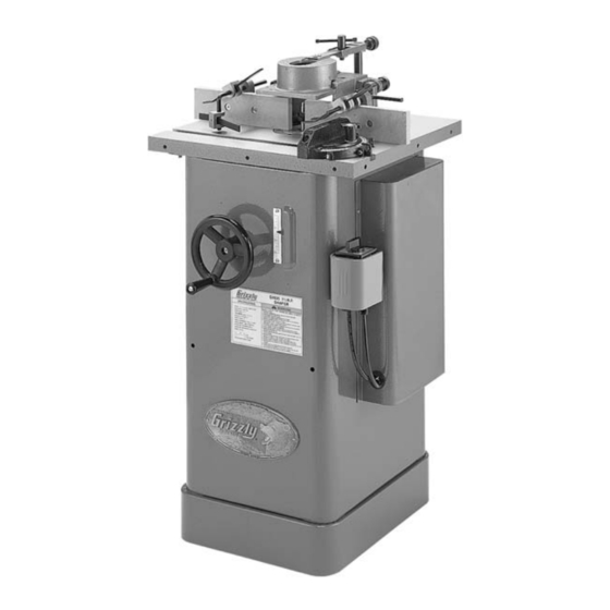
Machine Description and it helps us determine if updated documenta- tion is available for your machine. The Model G1035/G1035P is intended for home and medium-duty professional use. This shaper incorporates a 1 ⁄... -
Page 5: Components & Terminology
Spindle Height Motor Cover Scale ON/OFF Reversing Switch w/Padlock Figure 2. Model G1035P shown. To reduce the risk of serious injury when using this machine, read and understand this entire manual before beginning any operations. Model G1035/G1035P (Mfg. Since 4/10) -
Page 6: G1035/G1035P Data Sheet
MACHINE DATA SHEET Customer Service #: (570) 546-9663 · To Order Call: (800) 523-4777 · Fax #: (800) 438-5901 MODEL G1035/G1035P 1-1/2 HP SHAPER MODEL G1035 1‐1/2 HP SHAPER Product Dimensions: Weight................................195 lbs. Width (side-to-side) x Depth (front-to-back) x Height..............22 x 25 x 40-1/2 in. - Page 7 The information contained herein is deemed accurate as of 12/26/2017 and represents our most recent product specifications. Model G1035 PAGE 2 OF 2 Due to our ongoing improvement efforts, this information may not accurately describe items previously purchased. Model G1035/G1035P (Mfg. Since 4/10)
-
Page 8: Section 1: Safety
Everyday ery. Never operate under the influence of drugs or eyeglasses are NOT approved safety glasses. alcohol, when tired, or when distracted. Model G1035/G1035P (Mfg. Since 4/10) - Page 9 EXPERIENCING DIFFICULTIES. If at any time debris. Make sure they are properly installed, you experience difficulties performing the intend- undamaged, and working correctly BEFORE ed operation, stop using the machine! Contact our operating machine. Technical Support at (570) 546-9663. Model G1035/G1035P (Mfg. Since 4/10)
-
Page 10: Additional Safety For Shapers
Use the overhead safety guard when the adjustable fence is not in place. CUTTER POSITIONING: Keep the cutters on the underside of the workpiece whenever possible to reduce operator exposure to the moving cutter. Model G1035/G1035P (Mfg. Since 4/10) -
Page 11: Section 2: Power Supply
Nominal Voltage ........240V meets the specified circuit requirements. Cycle ............60 Hz Phase ........... Single-Phase Circuit Rating ........15 Amps Plug/Receptacle ......NEMA 6-15 Model G1035/G1035P (Mfg. Since 4/10) -
Page 12: Grounding Requirements
Additionally, it must Current Carrying Prongs meet the following size requirements: Minimum Gauge Size ......14 AWG 6-15 PLUG Maximum Length (Shorter is Better)..50 ft. Grounding Prong Figure 4. Typical 6-15 plug and receptacle. -10- Model G1035/G1035P (Mfg. Since 4/10) - Page 13 Wire Nut (14 AWG x 1) ....... 1 Terminal • Plug 6-15 ............ 1 Screws To convert the Model G1035/G1035P to 240V: DISCONNECT SHAPER FROM POWER! Figure 6. Motor rewired for 240V. Cut off the included plug. Close and secure the motor junction box.
-
Page 14: Section 3: Setup
IMPORTANT: Save all packaging materials until you are completely satisfied with the machine and have resolved any issues between Grizzly or the shipping agent. You MUST have the original pack- aging to file a freight claim. It is also extremely helpful if you need to return your machine later. -
Page 15: Inventory
"-20 x ⁄ " ....2 —Flat Washers ⁄ " ........4 —Flat Head Screws ⁄ "-18 x 1 ⁄ " ....4 —Hex Nuts ⁄ " .......... 4 Figure 9. Box 3 inventory. -13- Model G1035/G1035P (Mfg. Since 4/10) -
Page 16: Cleanup
Repeat Steps 2–3 as necessary until clean, then coat all unpainted surfaces with a quality metal protectant to prevent rust. -14- Model G1035/G1035P (Mfg. Since 4/10) -
Page 17: Site Considerations
Only install in an Shadows, glare, or strobe effects that may distract access restricted location. or impede the operator must be eliminated. Wall Minimum 30" 25" 22" Figure 10. Minimum working clearances. -15- Model G1035/G1035P (Mfg. Since 4/10) -
Page 18: Assembly
Remove the power switch cords, the FWD/ REV switch and grommet through the motor cover opening, as shown in Figure 12. Most of your Model G1035/G1035P has been assembled at the factory, but some parts must be assembled or installed after delivery. - Page 19 Re-install the remaining fasteners removed in flat part of the handwheel shaft. Step 2. 13. Thread the handle into the handwheel, and 10. Re-install the rear cover. tighten the nut on the handle against the handwheel. -17- Model G1035/G1035P (Mfg. Since 4/10)
-
Page 20: Spindle
Place the spindle/drawbar into the spindle cartridge at the top of the table. Line up the keyway on the spindle with the locating pin at the top of the spindle cartridge (see Figure The Model G1035/G1035P comes with ⁄ " & ⁄... -
Page 21: Table Inserts
Place a 14mm wrench on the drawbar nut (see Figure 19). The Model G1035/G1035P is supplied with two inserts that give you three possible diameter openings in the shaper table surface. Use the smallest opening that a particular cutter will allow. -
Page 22: Fence Assembly
To protect yourself, read and follow the entire manual carefully and do additional research on shop made guards and safety jigs. -20- Model G1035/G1035P (Mfg. Since 4/10) -
Page 23: Hold-Downs
Position the hold-downs according to the size of your workpiece. Tighten the set screws in the fence brackets and the hold-down brackets to fix the position of the hold-downs. Remove the hold-down assembly when not in use. -21- Model G1035/G1035P (Mfg. Since 4/10) -
Page 24: Dust Collection
DO NOT pull by the cord as this may damage the wires inside. Figure 26. The Model G4840 dust hood. (Check with the current Grizzly catalog or www.grizzly. com to purchase.) Tug the hose to make sure it does not come off. -
Page 25: Test Run
— Investigate and correct strange or unusual noises or vibrations before operating the machine further. Always disconnect the machine from power when investigating or correcting potential problems. -23- Model G1035/G1035P (Mfg. Since 4/10) -
Page 26: Section 4: Operations
OMMEND that you read books, review industry trade magazines, or get formal training before beginning any projects. Regardless of the content in this section, Grizzly Industrial will not be held liable for accidents caused by lack of training. -24- Model G1035/G1035P (Mfg. Since 4/10) -
Page 27: Basic Controls
Spindle Elevation Handwheel Figure 30. Elevation handwheel/scale and spindle height lock. Figure 32. Minimum lock shaft requirements. -25- Model G1035/G1035P (Mfg. Since 4/10) -
Page 28: Workpiece Inspection
On the contrary, a workpiece supported on the bowed side will rock during a cut and could cause kickback or severe injury. -26- Model G1035/G1035P (Mfg. Since 4/10) -
Page 29: Speed Changes
Speed Changes Cutter Installation The Model G1035/G1035P Shaper is equipped The model G1035/G1035P operates at speeds with a special high speed V-belt. It is designed to of 7,000 and 10,000 RPM. Large cutters (3 ⁄ " or withstand the vibration and sudden shock loads greater) must be operated at the slower speed. -
Page 30: Spindle Height
Move the spindle up or down with the eleva- More detailed information concerning fence tion handwheel until the desired position is adjustments is covered in Straight Shaping on obtained. Page 30. Lock the spindle into position. Figure 37. Spindle height lock. -28- Model G1035/G1035P (Mfg. Since 4/10) -
Page 31: Box Guards
You must use a box guard (see Figure 39) while fit your specific application. shaping workpieces to provide additional protec- tion for your hands. However, Grizzly Industrial is not able to provide a box guard with your shaper due to variables beyond our control, including the dimensions and orientation of your workpiece. -
Page 32: Straight Shaping
A test piece can help determine the best setting. Select the wood for the test piece that most closely resembles the actual workpiece. -30- Model G1035/G1035P (Mfg. Since 4/10) - Page 33 Direction of Feed Run a test piece through the shaper (see Figure 45. Cut end grain first. Figure 44). End View Outfeed Infeed Fence Fence Direction of Feed Figure 44. Partial feed fence adjustment. -31- Model G1035/G1035P (Mfg. Since 4/10)
-
Page 34: Shaping Small Stock
We recommend using ball bearing collars and we carry an extensive line that is designed for Always use hold-downs or featherboards use with Grizzly shapers. See our current catalog when shaping small or narrow stock. These or website for listings. -
Page 35: Irregular Shaping
After the cut has been started, the work should be swung away from the starting pin and is supported just by the rub collar, as shown by the broken line positions shown in Figure 50. ALWAYS FEED AGAINST THE ROTATION OF THE CUTTER. -33- Model G1035/G1035P (Mfg. Since 4/10) - Page 36 Figure 51. Inserting starting pin. Figure 53. Use starting pin substitute when needed. (Guard removed for clarity.) Use some type of hold-down fixture and guard when doing freehand work (see Figure 52). -34- Model G1035/G1035P (Mfg. Since 4/10)
-
Page 37: Pattern Work
The workpiece must be fixed securely to the jig. Figure 54. Using a template and a rub collar for pattern shaping. -35- Model G1035/G1035P (Mfg. Since 4/10) -
Page 38: Section 5: Accessories
(same principal as router bits with guide bearings). Use them below, in between or above cutters. Figure 57. G1706 Cast Iron Wing. G1705—Bit Spindle Router bit spindle for use with our G1035 1 ⁄ Shaper. For ⁄ ” and ⁄... - Page 39 G4840—3" Dust Hood G1519—4" x 3" Reducer This dust hood connects the G1035 to any 3" dust We carry hose diameters for many different appli- collection hose. Attaches to blade guard. cations. 3” and 4” x 6” hose sections are great for connecting dust collection fittings.
- Page 40 Also compatible with safety glasses! Figure 65. Recommended products for protect- ing unpainted cast iron/steel part on machinery. Figure 67. Half-mask respirator with disposable cartridge filters. -38- Model G1035/G1035P (Mfg. Since 4/10)
-
Page 41: Section 6: Maintenance
SECTION 6: MAINTENANCE Cleaning Always disconnect power to the machine before Cleaning the Model G1035/G1035P is relatively performing maintenance. easy. Vacuum excess wood chips and sawdust, Failure to do this may and wipe off the remaining dust with a dry cloth. -
Page 42: Lubrication
Carefully spread the casting to reduce the Re-install the rear cover. risk of the bearing housing falling and pinching fingers. To reduce damage, place a pad underneath the housing. The casting will break if too much pressure is applied. -40- Model G1035/G1035P (Mfg. Since 4/10) -
Page 43: V-Belt Tension & Replacement
Do not remove the bolts completely. Figure 70. Location of motor mount hex bolts. — If the V-belt is cracked, excessively worn, or damaged, slide the motor to the right, then replace the V-belt. -41- Model G1035/G1035P (Mfg. Since 4/10) -
Page 44: Section 7: Service
7. Tighten mounting bolts; relocate/shim machine. 8. Motor fan rubbing on fan cover. 8. Fix/replace fan cover; replace loose/damaged fan. 9. Motor bearings at fault. 9. Test by rotating shaft; rotational grinding/loose shaft requires bearing replacement. -42- Model G1035/G1035P (Mfg. Since 4/10) - Page 45 1. Inconsistent feed speed. 1. Move smoothly or use a power feeder. the cut. 2. Inconsistent pressure against the fence and 2. Apply constant pressure. rub collar. 3. Fence not adjusted correctly. 3. Adjust fence. -43- Model G1035/G1035P (Mfg. Since 4/10)
-
Page 46: Table Insert Adjustment
Note: Notice that there is a barrel screw table top in all directions. underneath each of the Phillips screws (see Figure 72). Figure 72. Insert ring barrel screw. -44- Model G1035/G1035P (Mfg. Since 4/10) -
Page 47: Fence Board Alignment
— If there is a gap between the straight- edge and the fence boards, use shims as needed between the fence boards and the mounting brackets to make the boards completely parallel with each other along their entire length. -45- Model G1035/G1035P (Mfg. Since 4/10) -
Page 48: Aligning Pulleys
Using the straightedge as a guide, rotate the before reconnecting the machine to power. motor assembly until the motor pulley is par- allel with the spindle pulley, then re-tighten the four motor mount hex bolts. -46- Model G1035/G1035P (Mfg. Since 4/10) -
Page 49: Gib Adjustment
Evenly adjust the set screws small amounts, then test the results. When you are satisfied with the gib adjust- ment, re-tighten the jam nuts without turning the set screws. Re-check the gib adjustment. If necessary, repeat this procedure. -47- Model G1035/G1035P (Mfg. Since 4/10) -
Page 50: Section 8: Wiring
Technical Support at (570) 546-9663. The photos and diagrams included in this section are best viewed in color. You can view these pages in color at www.grizzly.com. -48- Model G1035/G1035P (Mfg. Since 4/10) -
Page 51: Wiring Diagram
Wiring Diagram Spindle Switch STOP 120V Single-Phase Motor (Pre-Wired) Start Capacitor 300 MFD 125 VAC Neutral Ground 240V Single-Phase Motor 120V NEMA 5-15 Plug (Included) Ground Start Capacitor 240V Single-Phase 300 MFD 125 VAC NEMA 6-15 Plug (As Recommended) Figure 79. FWD/REV switch wiring. Figure 80. -
Page 52: Section 9: Parts
SECTION 9: PARTS Main 15V2 29V2 26V2 29V2 32V2 35V2 36V2 51 62 -50- Model G1035/G1035P (Mfg. Since 4/10) - Page 53 PN07 HEX NUT 10-24 PW07 FLAT WASHER 5/16 PHTEK1 TAP SCREW #6 x 1/2" 15V2 P1035015V2 FENCE MOUNT LH 3/8 V2.01.09 (G1035) P1026041 SCALE 15V2 P1035P015V2 FENCE MOUNT LH 3/8 V2.01.09 (G1035P) PTLW01 EXT TOOTH WASHER #10 PCAP14 CAP SCREW 3/8-16 X 1...
-
Page 54: Motor
Motor 145-2 145-3 145-7 145-4 145-8 145-5 145-1 145-6 145-9 144A 141A 147A 128A 131A 127A 129A 115A 108-1 104A 103A 123-1 107A -52- Model G1035/G1035P (Mfg. Since 4/10) - Page 55 LOCK WASHER 3/8 129A PB12 HEX BOLT 5/16-18 X 1-1/4 PSS02 SET SCREW 5/16-18 X 3/8 131A PB19 HEX BOLT 1/4-20 X 1/2 P1035151 HANDWHEEL LOAD WASHER PW06 FLAT WASHER 1/4 P1035159 TOP MOTOR BRACE -53- Model G1035/G1035P (Mfg. Since 4/10)
-
Page 56: Spindle
SPINDLE WASHER 1/2 X 26 X 3 P1035214 BEARING HOUSING P1026224 SPINDLE WASHER 3/4 X 32 X 3 P1035215 DRAWBAR P1026226 SPINDLE WRENCH SET PR13M EXT RETAINING RING 65MM P1035234 SPINDLE ASSEMBLY P1035217 STEP PULLEY PWR1214 WRENCH 12 X 14 -54- Model G1035/G1035P (Mfg. Since 4/10) -
Page 57: Safety Guard
EXTENSION BAR PB21 HEX BOLT 3/8-16 X 3/4 P1035415 GUARD (G1035) P1035405 EXTENSION BRACKET (G1035) P1035P415 GUARD (G1035P) P1035P405 EXTENSION BRACKET (G1035P) PFH04 FLT HD SCR 1/4- 20 X 5/8 P1026306 LOCK KNOB ASSEMBLY -55- Model G1035/G1035P (Mfg. Since 4/10) -
Page 58: Hold-Downs
Hold-Downs PART # DESCRIPTION PART # DESCRIPTION P1035501 HOLD DOWN BAR P1035503 HOLD DOWN BRACKET P1035502 HOLD DOWN PSS03 SET SCREW 1/4-20 X 3/8 -56- Model G1035/G1035P (Mfg. Since 4/10) -
Page 59: Miter Gauge
MITER BAR P1026612 MITER GAUGE SCALE 604A P1035604A MITER GAUGE ASSY V1.10.02 PRP14M ROLL PIN 3 X 6 PN07 HEX NUT 10-24 P1026615 MITER GAUGE HINGE PIN 608A PSS32 SET SCREW 10-24 X 3/4 -57- Model G1035/G1035P (Mfg. Since 4/10) -
Page 60: Label Placement
Safety labels help reduce the risk of serious injury caused by machine hazards. If any label comes off or becomes unreadable, the owner of this machine MUST replace it in the original location before resuming operations. For replacements, contact (800) 523-4777 or www.grizzly.com. -58-... - Page 61 Would you recommend Grizzly Industrial to a friend? _____ Yes _____No Would you allow us to use your name as a reference for Grizzly customers in your area? Note: We never use names more than 3 times. _____ Yes _____No 10.
- Page 62 FOLD ALONG DOTTED LINE Place Stamp Here GRIZZLY INDUSTRIAL, INC. P.O. BOX 2069 BELLINGHAM, WA 98227-2069 FOLD ALONG DOTTED LINE Send a Grizzly Catalog to a friend: Name_______________________________ Street_______________________________ City______________State______Zip______ TAPE ALONG EDGES--PLEASE DO NOT STAPLE...
-
Page 63: Warranty & Returns
WARRANTY & RETURNS Grizzly Industrial, Inc. warrants every product it sells for a period of 1 year to the original purchaser from the date of purchase. This warranty does not apply to defects due directly or indirectly to misuse, abuse, negligence, accidents, repairs or alterations or lack of maintenance.