Table of Contents
Advertisement
Quick Links
D8T Series Turret Camera
User Manual
Thank you for purchasing our product. If there are any
questions, or requests, do not hesitate to contact the
dealer.
This manual applies to the models below:
Type
Type I Camera
Type II Camera
Type III Camera
This manual may contain technical incorrect places or
printing errors, and the content is subject to change
without notice. The updates will be added to the new
version of this manual. We will readily improve or
update the products or procedures described in the
manual.
Questo manuale d'istruzione è fornito da trovaprezzi.it. Scopri tutte le offerte per
DS-2CE56D8T-IT3F
o cerca il tuo prodotto tra le
migliori offerte di Videosorveglianza
TURBO HD
User Manual
Model
DS-2CE56D8T-IT1F
DS-2CE56D8T-IT3F
DS-2CE56D8T-ITMF
DS-2CE56D8T-VPITF
0100001080926
Hikvision
Advertisement
Table of Contents

Related Manuals for HIKVISION DS-2CE56D8T-IT3F


Summary of Contents for HIKVISION DS-2CE56D8T-IT3F
- Page 1 Questo manuale d’istruzione è fornito da trovaprezzi.it. Scopri tutte le offerte per Hikvision DS-2CE56D8T-IT3F o cerca il tuo prodotto tra le migliori offerte di Videosorveglianza TURBO HD D8T Series Turret Camera User Manual User Manual Thank you for purchasing our product. If there are any questions, or requests, do not hesitate to contact the dealer.
- Page 2 Regulatory Information FCC Information Please take attention that changes or modification not expressly approved by the party responsible for compliance could void the user’s authority to operate the equipment. FCC compliance: This equipment has been tested and found to comply with the limits for a Class A digital device, pursuant to part 15 of the FCC Rules.
- Page 3 Safety Instruction These instructions are intended to ensure that user can use the product correctly to avoid danger or property loss. The precaution measure is divided into “Warnings” and “Cautions”. Warnings: Serious injury or death may occur if any of the warnings are neglected.
- Page 4 1 Introduction 1.1 Product Features The main features are as follows: High performance CMOS sensor IR cut filter with auto switch OSD menu with configurable parameters Auto white balance Internal synchronization SMART IR mode 3-axis adjustment ...
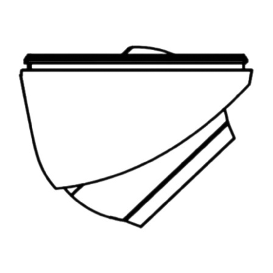
- Page 5 1.2.3 Overview of Type III Camera Power Cord 12 VDC Video Cable Mounting Base Switch Button Pan Adjusting Screw IR LED Tilt Adjusting Screw Lens Black Liner Bubble Safty Rope Figure 1-3 Overview of Type III Camera Note: Press and hold the switch button for 5 seconds to switch the video output.
-
Page 6: Installation
2 Installation Before you start: Make sure that the device in the package is in good condition and all the assembly parts are included. Make sure that all the related equipment is power-off during the installation. Check the specification of the products for the ... - Page 7 Note: The supplied screw package contains self-tapping screws, and expansion bolts. For cement wall/ceiling, expansion bolts are required to fix the camera. For wooden wall/ceiling, self-tapping screws are required. 6. Route the cables through the cable hole, or the side opening.
- Page 8 4. Drill the screw holes according to the drill template, and the cable hole (optional) on the ceiling. Figure 2-7 Drill Template Note: Drill the cable hole in the center of the drill template, when adopting the ceiling outlet to route the cable. 5.
- Page 9 1). Hold the camera body and rotate the enclosure to adjust the pan position [0° to 360°]. 2). Move the camera body up and down to adjust the tilt position [0° to 75°]. 3). Rotate the camera body to adjust the rotation position [0°...
-
Page 10: Adjusting Screw
0° to 355° Adjusting Screw 0° to 75° 0° to 355° Figure 2-14 Type I Camera 2-Axis Adjustment 1). Loosen the tilt adjusting screw to adjust the tilt position [0° to 75°]. 2). Hold the black liner to adjust the pan position [0° to 355°]. -
Page 11: Menu Description
3 Menu Description Purpose: Call the menu by clicking button on the PTZ Control interface, or call preset No.95. Steps: 1. Connect the camera with the TVI DVR, and the monitor, shown as the figure 3-1. Figure 3-1 Connection 2. Power on the analog camera, TVI DVR, and the monitor to view the image on the monitor. -
Page 12: Slow Shutter
5. Click the direction arrow to control the camera. (1) Click up/down direction button to select the item. (2) Click Iris + to confirm the selection. (3) Click left/right direction button to adjust the value of the selected item. 3.1 VIDOE FORMAT When switching the video output as CVBS, you can ... - Page 13 SLOW SHUTTER SLOW SHUTTER increases the exposure time on a single frame, which makes a camera more sensitive to the light so it can produce images even in low lux conditions. You can set the SLOW SHUTTER function as OFF, x2, x4, x6, x8, x10, x12, x14, or x16 according to the different light conditions.
-
Page 14: Video Settings
IR LIGHT You can turn on/off the IR LIGHT to meet the requirements of different circumstances. SMART IR The Smart IR function is used to adjust the light to its most suitable intensity, and prevent the image from over exposure. -
Page 15: Motion Detection
WHITE BALANCE MANUAL MODE R-GAIN B-GAIN BACK EXIT SAVE & EXIT Figure 3-7 MANUAL MODE BRIGHTNESS Brightness refers to the brightness of the image. You can set the brightness value from 1 to 9 to darken or brighten the image. The higher the value is, the brighter the image is. -
Page 16: Motion Det
MOTION DET Figure 3-8 MOTION Select a MOTION area. Set the MODE as ON. Click the up/down/left/right button to define the position, and the size of the area. Set the SENSITIVITY from 1 to 9. PRIVACY The privacy mask allows you to cover certain areas which you don’t want to be viewed, or recorded.