Table of Contents
Advertisement
Quick Links
Advertisement
Table of Contents

Related Manuals for Baumatic BCG600SS


Summary of Contents for Baumatic BCG600SS
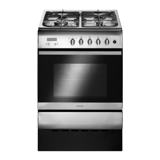
- Page 1 BCG600SS 60 cm Single cavity gas cooker with wok burner...
- Page 2 User Manual for your Baumatic BCG600SS 60 cm Single cavity gas cooker with wok burner NOTE : This User Instruction Manual contains important information, including safety & installation points, which will enable you to get the most out of your appliance. Please keep it in a safe place so that it is easily available for future reference;...
-
Page 3: Table Of Contents
Contents Environmental note Important safety information 5 – 8 Specifications 9 – 12 Dimensions Specifications Standard accessories 9 - 10 Electrical details Gas details Product features 10 - 11 Control panel 11 - 12 Oven timer Setting and using the oven timer Setting the time of day Setting the minute minder function Using the oven... -
Page 4: Environmental Note
Environmental note o The packaging materials that Baumatic uses are environmentally friendly and can be recycled. o Please discard all packaging material with due regard for the environment. -
Page 5: Important Safety Information
Important safety information Your safety is of the utmost importance to Baumatic. Please make sure that you read this instruction booklet before attempting to install or use the appliance. If you are unsure of any of the information contained in this ooklet, please contact the Baumatic Advice Line. - Page 6 Safety o Baumatic strongly recommend that babies and young children are prevented from being near to the appliance and not allowed to touch the appliance at any time. During and after use, all surfaces will become hot. o If it is necessary for younger family members to be in the...
- Page 7 o Do not store chemicals, food stuffs, pressurised containers in or on the cooker or in cabinets immediately above or next to the cooker. o Do not heat up unopened food containers, as pressure can build up which may cause the container to burst. o Do not place flammable or plastic items on or near the hob burners, these types of materials should also not be placed in the oven or the compartment below the oven.
- Page 8 Please see the specific section of this booklet that refers to installation. o Baumatic Ltd. declines any responsibility for injury or damage, to person or property, as a result of improper use or installation of this appliance.
-
Page 9: Specifications
pecifica tions Product dimensions: Height: 900 - 920 mm Width: 600 mm Depth: 600 mm Product specifications: o 4 zone gas hob: o 2 x 1.75 kW semi-rapid burne o 1 x 3.00 kW wok b urner 1 x 1.00 kW aux iliary burner o 2 function oven o Oven gross / net capacity: 65 /... -
Page 10: Electrical Details
o 1 x Wire shelf o 1 x Trivet o LPG conversio n jets Electrical details Rated Voltage: 220 - 240 Vac 50 Hz Supply Connection: 3 A (double pole switched fused outlet with 3mm contact gap) Max Rated Inputs 0.025 kW ains Supply Lead: 3 core x 2 mm²... -
Page 11: Control Panel
9) Heavy duty cast iron pan stands 0) Removable grill deflector plate (not shown) 11) Storage compartment (not shown) For future reference please record the following information which can be found on the rating plate and the date of purchase which can be und on your sales invoice. -
Page 12: Oven Timer
Thermostat control knob (hob) o Use the control knob of relevant cooking zone temperature intensity. ven timer ) Alarm stop icon (press minus button to stop alarm). ) Timer minus button. ) Timer plus button. ) Time-setting mode indicator (press plus and minus buttons gether to enter this mode). -
Page 13: Setting And Using The Oven Timer
Setting and using the oven timer Setting the time of day Before using the oven for the first time you should set the time of day. o Press the plus (3) and minus (2) buttons simultaneously to enter the time-setting mode. The display will automatically show “12.00”. -
Page 14: Using The Main Oven
o You should make sure that any windows in the room are left open during this process. o It is advisable for you not to remain in the room whilst the burning off process is taking place. o You should leave each oven on maximum setting for 30 – 40 minutes. -
Page 15: Using The Grill
o Once the burner is lit, turn the knob to a setting from 1 to 8 to set the temperature. o The table below shows what setting you should select for the respondin te per atu : Setting Temp (°C) 130 140 150 170 190 230 245 250 o The oven light can be turned on anytime by pressing the top half of the ignition button. -
Page 16: Cooking Guidelines
a lower heat level, turn the control dial to the small flame position. o You can turn the light on any time by pressing the bottom half of the ignition button. Press this button again to turn the light off. o The grill has a flame failure safety device. -
Page 17: Warnings
o You should pre-heat the oven and not place food inside of it is properly heated o Before cooking, check that any unused accessories are removed from the oven. o Place cooking trays in the centre of the oven and leave gaps between the trays to allow air to circulate. -
Page 18: Using The Hob Top Zones
Using the hob top zones Each zone on the gas hob top is controlled by a control knob. o To turn on a cooking zone use the relevant control knob for the zone you wish to use. o Press and turn the control knob to the large flame position. -
Page 19: Cleaning And Maintenance
o The burner flame must never extend beyond the diameter of the pan. o Use flat bottomed pans only o When possible, keep a lid on the pan whilst cooking. o Cook vegetables with as little water as possible, to reduce cooking times. -
Page 20: Cleaning The Gas Hob Top
Any damage that is c aused to the appliance by a cleaning product will not be fixed by Baumatic free of charge, even if the appliance is within the guarantee period. leaning the gas hob top o Remove the dirty pan supports from the hob and place in warm soapy water for some time. -
Page 21: Cleaning The Oven
o Dry all the elem ents of the burner carefully as wet elements may not light properly. Assemble the clean and dry burners carrying out the disassembly steps in reverse order. Cleaning the oven o The oven compartment is coated with vitreous enamel. To clean particularly difficult burnt spots a special oven cle aning agent may be used. -
Page 22: Removing The Oven Door For Cleaning
ving the oven door for cleaning o facilitate the cleaning of the inside of the cooker and the outer frame of the oven, the door can be removed as follows:- o The hinges (A) have two movable bolts on them (B). o If you raise both of the movable bolts (B), then the hinges (A) are released from the oven housing. -
Page 23: Installation
Install ation The installation must be carried out by a suitably qualified person, in accordance with the current version of the following. o UK Regulations and Safety Standards or their European Norm Replacements. o Building Regulations (issued by the Department of the Environment). - Page 24 (including the burners). o Baumatic do not recommend that the cooker is positioned below wall cupboards, as the heat and steam from the appliance and what is being cooked, may damage the cupboard and its contents.
-
Page 25: Ventilation Requirements
o The cooker is fitted with four feet that can be adjusted to match height your kitchen cabinets. o If the cooker is not level or is unstable due to an uneven floor surface, use the adjustable feet to alter each corner until the cooker is level. -
Page 26: Securing The Safety Chains
o Decide on a suitable wall location for fitting the anchor brackets directly behind each cooker safety chain. o Hold the chain anchor up to the wall where it will be required and mark the fixing holes. o Drill the fixing holes and fix the chain anchors to the wall using the screws provided and suitable wall plugs for the type of wall being fixed to. -
Page 27: Electrical Connection
o Insert the screw head into the top hole of the anchor bracket by tilting it sideways so that it is at an angle to the top hole when it is inserted. o When the screw head is fully engaged in the bracket, tilt it upwards so that it is straight, and tighten the hex nut to secure the end chain link into position. -
Page 28: Gas Connection
Conversion for use on LPG and other gases must only be undertaken by a qualified person. For information on the use of other gases, please contact the Baumatic Technical Department. o The cooker must be installed by a qualified person, in... -
Page 29: Gas Safety
Gas Safety (Installation and Use) Regulations o It is the law that all gas appliances are installed by competent persons in accordance with the current edition of the Gas Safety Installation and Use Regulations. o It is in your interest and that of safety to ensure compliance with the law. - Page 30 o IMPORTANT: THE FIBRE WASHERS SHOWN IN THE ABOVE DIAGRAM MUST BE IN PLACE WHEN CONNECTING THE ADAPTOR ELBOW. o Connection to the cooker should be made with an approved appliance flexible connection to BS 669. o If the cooker has been converted for use with LPG, then it should be connected to the gas supply using an appropriate bayonet type hose.
-
Page 31: Gas Adjustment (Conversion To Lpg For The Hob Top)
Gas adjustment (Conversion to LPG for the hob top) All work must be carried out by a GASSAFE registered engineer. IMPORTANT: Always isolate the cooker from the electricity supply before changing the injectors and/or adjusting the minimum flow of the burners. o Remove the pan supports, burner cap and burner rings. -
Page 32: Minimum Flow Adjustment For Hob Gas Taps
Minimum flow adjustment for hob gas taps. All work must be carried out by a GASSAFE registered engineer. o Ignite the large (rapid) burner and set the control knob to the minimum position. o Remove the control knob to access a small adjusting screw. o Using a suitable screwdriver, turn the screw clockwise to decrease the flow of gas and make the flame smaller. -
Page 33: Gas Adjustment (Conversion To Lpg For The Oven And Grill)
Gas adjustment (Conversion to LPG for the oven and grill) work must carried GASSAFE registered engineer. IMPORTANT: Always isolate the cooker from the electricity supply before changing the injectors and/or adjusting the minimum flow of the burners. o Before you can change the injectors on the grill and oven burners, you must unscrew the burners from their fixing brackets. -
Page 34: Minimum Flow Adjustment For The Oven And Grill Burners
o Unscrew the injector and replace it with the required injector for the new gas supply according to the table below. Burner Type Gas Type Pressure Injector Power Mbar Marking (Kw) (1/100mm) Max Min Oven Burner Natural 1.05 Liquid Gas 28..30/37 0.72 Grill Burner Natural... - Page 35 o When all the screws have been removed, slide the hob from the back to the front and lift it off the support brackets which hold the hob down at the front of the cooker. o To take off the control panel, remove the screws fixing the control panel.
- Page 36 o Locate the adjusting screws for the grill and oven burners. These will be positioned to the left hand side of the grill and oven thermostat taps. o With the control panel removed, refit the oven and gas thermostat control knobs. Ignite each burner separately and set the control knob to the minimum position.
-
Page 37: My Appliance Isn't Working Correctly
My appliance isn’t working correctly The gas oven burner or grill burner do not light. * Check that the oven is switched on at your mains supply. * Check that the fuse in the spur outlet doesn’t need replacing. * Check that there is not a problem with your gas supply Food is cooking too quickly or too slowly. - Page 38 Or any installation other than the one specified by Baumatic Ltd. has been completed. Please refer to the conditions of guarantee that appear on the...
-
Page 39: Contact Details
Czech Republic Baumatic CR spol s.r.o. Průmyslová zóna Sever 696 460 11 Liberec 11 United Kingdom Czech Republic Baumatic Ltd., Baumatic Buildings, +420 483 577 200 6 Bennet Road, Reading, Berkshire www.baumatic.cz RG2 0QX United Kingdom Slovakia Baumatic Slovakia, s.r.o.