Table of Contents
Advertisement
Quick Links
Advertisement
Table of Contents

Related Manuals for Honeywell GLEN ALDEN


Summary of Contents for Honeywell GLEN ALDEN
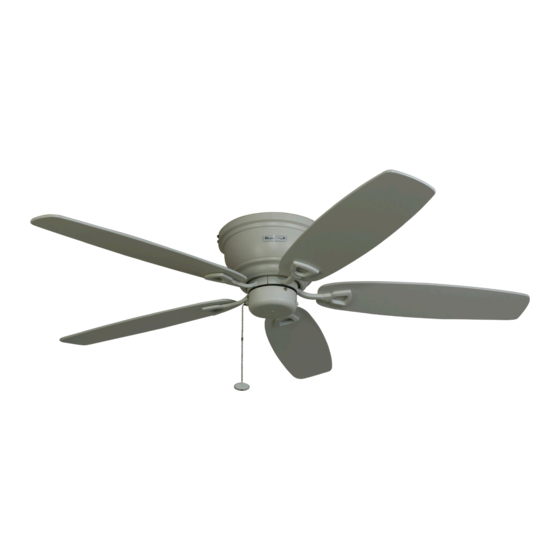
- Page 1 GLEN ALDEN 52” CEILING FAN MODEL #50180 Español p. 15 Questions, problems, missing parts? Before returning to your retailer, call our customer service department at 1-877-361-3883, Monday - Thursday, 8 am - 6 pm, EST and Friday, 8 am - 5 pm, EST.
-
Page 2: Table Of Contents
WELCOME TABLE OF CONTENTS PREPARATION Before beginning the assembly of this product, ensure Care and Maintenance ......2 that all parts are present. -
Page 3: Package Contents
PACKAGE CONTENTS Unpack your fan and check the contents. You should have the following items: 1. Upper Mounting Bracket 2. Motor with Lower Mounting Bracket 3. Blade (5) 4. Blade Arm (5) 5. Switch Housing Cap 6. Motor Housing 7. Loose parts bags containing (not shown): Mounting hardware, electrical hardware, pull chains, wire connectors, etc. -
Page 4: Safety Information
SAFETY INFORMATION Please read and understand this entire manual before attempting to assemble, operate, or install the product. • Before you begin installing the fan, disconnect the power by removing fuses or turning off the circuit breakers. • Make sure that all electrical connections comply with local codes, ordinances, the National Electrical Code, and ANSI/NFPA 70-199. -
Page 5: Mounting Bracket Installation
MOUNTING BRACKET INSTALLATION 1. Turn off the circuit breakers and the wall switch to Fig. 1 the fan supply line lead (Fig. 1). DANGER: Failure to disconnect the power supply prior to installation may result in serious injury or death. 2. -
Page 6: Hanging Your Fan
HANGING YOUR FAN 4. Remove the four bracket screws from underneath Fig. 4 the lower mounting bracket and save for later use (Fig. 4). Bracket Screw Washer Bracket Screw Fig. 5 5. Place tab on the lower mounting bracket into slot in the upper mounting bracket. -
Page 7: Wiring
WIRING CAUTION Fig. 7 Be sure outlet box is properly grounded or that a ground (green or bare) wire is present. Black (live) WARNING White (neutral) If house wires are different colors than referred to in the following step, stop immediately. A professional Bare/Green (ground) electrician is recommended to determine wiring. -
Page 8: Motor Housing Installation
MOTOR HOUSING INSTALLATION 9. Remove the ten motor screws from the underside of Fig. 9 the motor. Set aside for blade arm assembly (Fig. 9). Motor Screw Motor Screw 10. Temporarily lift the motor housing to the mounting Fig. 10 bracket to determine which two motor housing screws in the sides of the mounting bracket align Motor... -
Page 9: Blade Installation
BLADE INSTALLATION 12. The blades attach to blade arms using the Fast Fig. 12 Attach system. Align each twist lock connector in the direction of its corresponding hole in the blade. Place the blade Blade Arm over the twist lock connectors. Rotate each twist lock connector so that it is perpendicular to the hole in the blade. -
Page 10: Final Installation
FINAL INSTALLATION 14. Remove the three screws and washers from the Fig. 14 upper switch housing. Connect plug from the motor to the plug from the switch housing cap. Align holes in the switch housing cap with holes in upper switch housing. -
Page 11: Operating Installation
OPERATING INSTRUCTIONS 16. Use the fan reverse switch, located on the side Fig. 16 of the light kit, to optimize your fan for seasonal performance (Fig. 16). Using a ceiling fan will allow you to raise your thermostat in the summer and lower your thermostat in the winter without sacrificing comfort. -
Page 12: Replacement Parts List
REPLACEMENT PARTS LIST For replacement parts, call the customer service department at 1-877-361-3883, 8 a.m. - 6 p.m., EST, Monday - Thursday, 8 a.m. - 5 p.m., EST, Friday. MODEL 50180 PIECE DESCRIPTION PART# Blade Arm 50180-A Blade 50180-B Loose parts bags containing (not shown): Mounting hardware, blade attachment hardware, 50180-C... -
Page 13: Troubleshooting
TROUBLESHOOTING At least twice each year, lower the canopy to check the downrod assembly, and then tighten all screws on the fan. Clean the motor housing with only a soft brush or lint-free cloth to avoid scratching the finish. Clean the blades with a lint-free cloth. You may occasionally apply a light coat of furniture polish to wood blades for added protection. -
Page 14: Limited Lifetime Warranty
1-877-361-3883, Monday-Thursday, 8am - 6pm, EST and Friday, 8am - 5pm, EST. Please have a copy of the receipt as proof of purchase. The Honeywell Trademark is used under license from Honeywell International Hong Kong China Electric Appliance Manufacture Co., Ltd.