GE TiP LOGIQ 400 Quick Start Manual
Hide thumbs
Also See for TiP LOGIQ 400:
- Service manual (526 pages) ,
- Unpacking instructions manual (14 pages)

Related Manuals for GE TiP LOGIQ 400


Summary of Contents for GE TiP LOGIQ 400
- Page 1 All manuals and user guides at all-guides.com GE Medical Systems Training In Partnership LOGIQ Quick Start Guide 2237879–100 A Training in Partnership Program...
- Page 2 All manuals and user guides at all-guides.com...
-
Page 3: Technical Publications
All manuals and user guides at all-guides.com GE Medical Systems Technical Publications Direction 2237879-100 Revision 0 LOGIQ t 400 Quick Start Guide Copyright 1999 By General Electric Co. Operating Documentation... - Page 4 LOGIQ It applies to all versions of 4.02 software for the LOGIQ 400CL GE Medical Systems GE Medical Systems: Telex 3797371 P.O. Box 414, Milwaukee, Wisconsin 53201 U.S.A. (Asia, Pacific, Latin America, North America) GE Medical Systems Europe: T el: +49 (0) 212 28 02 208 Beethovenstraße 239, Postfach 11 05 60, D-42655 Solingen...
- Page 5 All manuals and user guides at all-guides.com DATE REASON FOR CHANGE April 27, 1999 Initial Release LIST OF EFFECTIVE PAGES PAGE REVISION PAGE REVISION NUMBER NUMBER NUMBER NUMBER TiP Cover Page Revision History A and B Title Page Quick Start 1 thru Quick Start 40 LOGIQ 400 Quick Start Guide Revision History A...
- Page 6 GPC (GE Medical Systems Global Product Configuration). If you need to know the latest revision, contact your distributor, local GE Sales Representative or in the USA call the GE Ultrasound Clinical Answer Center at 1-800-682-5327 or 414-524-5698.
- Page 7 All manuals and user guides at all-guides.com Introduction The Quick Start Guide (TRANSLATED) provides a step-by-step description of the basic features and operation of the LOGIQ 400. It is intended to be used in conjunction with the Basic User Manual in order to provide the information necessary to operate the system safely.
-
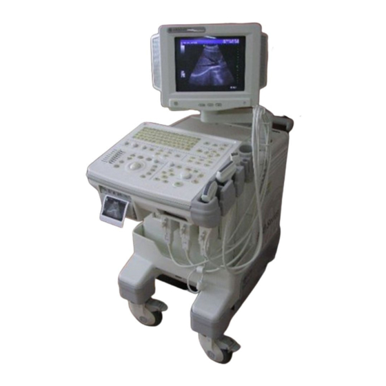
Page 8: Front View
All manuals and user guides at all-guides.com Front View The following are major features of the LOGIQ 400 system console. Most features come with the standard configuration, while other features are options to the standard console. VCR Microphone LOGIQ 400 Probe Holder MOD Drive Physio Panel *... -
Page 9: Back View
All manuals and user guides at all-guides.com Back View Circuit Breaker Î Î Î Î Î Air Filter Î Î Î Î Î Î Î Î Î Î Î Î Cable Access Î Î Î Peripheral Cable Access Door Handle for Pushing Monitor Arm Swivel Lock Color Monitor Optional Freeze/Record Foot Switch... - Page 10 All manuals and user guides at all-guides.com Power On To connect the system to the electrical supply: Ensure that the wall outlet is a minimum 15 amp dedicated circuit for 120 VAC (USA) or 7.5 amp dedicated circuit for 220–240 VAC (Europe). Make sure that the power switch is turned off.
- Page 11 All manuals and user guides at all-guides.com Power On (cont’d) During power up, the screen display changes as the system runs its self diagnostics. Start of diagnostic XXXXXXX XXXXXXX Version X.XX Version X.XX Version X.XX End of diagnostic LOGIQ 400 Quick Start Guide Quick Start 5 2237879–100 Rev.
-
Page 12: Control Panel Layout
All manuals and user guides at all-guides.com Control Panel Layout Keyboard Keyboard controls have been arranged according to function and usage. This helps minimize operator movement while scanning. Æ Ø Ç Alphanumeric Keys New Patient Probe Select Soft Menu Controls User Define Mode, Display and Record Measurement and Annotation... -
Page 13: Soft Menu Control Panel
All manuals and user guides at all-guides.com Soft Menu Control Panel The Soft Menu Display has 8 Top Menu selections (Mode, LOGIQ 400 MD Preset, Set Up, ECG, Archive, DICOM, AutoSeq and Cine) and 8 Sub Menu selections (varies depending on choice of Top Menu selection) available. -
Page 14: Probe Controls
All manuals and user guides at all-guides.com Probe Controls A probe is activated by pressing the Probe Select key. The appropriate port’s LED (light emitting diode) to the left of the key is lit. The second key is used to select (activate) the dedicated continuous wave Doppler (CWD) probe. -
Page 15: Starting An Exam
All manuals and user guides at all-guides.com Starting an Exam Patient Entry Menu Press the New Patient key at the beginning of each study to reset the system and enter new patient data. When the New Patient key is pressed, the Patient Entry menu appears. Ensure that the Blue Shift key is not active. -
Page 16: Application Presets
All manuals and user guides at all-guides.com Application Presets Select the exam category application preset, Preset LOGIQ 400 MD that best describes the desired study to be performed, from the factory default preset General Tech Fetal Newborn Diff Heart selections displayed on the monitor. Preset General Tech... -
Page 17: Scan Mode Controls
All manuals and user guides at all-guides.com Scan Mode Controls Select the desired display mode or combination of display modes (B-Mode, Pulsed Doppler, Color Flow Mode, M-Mode or Continuous Wave Doppler Mode). To select CWD Mode, press Blue Shift and X. CWD Mode is available for sector probe only. If the dual display mode (split screen) is desired, the L and R keys activate the Left or Right displayed image. -
Page 18: B-Mode Controls
All manuals and user guides at all-guides.com B-Mode Controls There are four Soft-Menu pages for B-Mode imaging adjustments. Dynamic Range—Controls how echo intensities are converted to shades of gray, thereby creating a range of gray scale that can be adjusted. Dynamic Gray Focus... - Page 19 All manuals and user guides at all-guides.com B-Mode Controls (cont’d) Biopsy Zone—Enables the electronic guidezone(s) available for the active probe. Biopsy Image Rejectn Edge Image Rotate—Rotates the single real-time or zoomed B-Mode image in 90 Zone Rotatn Enhance increments. 0 DEG Rejectn—Allows for the elimination of low level echoes from the display.
- Page 20 All manuals and user guides at all-guides.com B-Mode Controls (cont’d) The keyboard controls that effect B-Mode are as follows: TGC—Balances the image so brightness is consistent throughout the image. Move the slide pot to the right to increase or the left to decrease. Scan Area—Used to assign trackball control to adjust size/position B-Mode sector display, CFM window, and horizontal size/position of the real-time zoom window.
- Page 21 Display Format (Dual)— Left/Right split screen display. Reverse—The GE logo at the top of the sector wedge corresponds to the orientation mark on the probe body. When Reverse is active, the image flips and the GE logo switches to correspond to the probe mark.
- Page 22 All manuals and user guides at all-guides.com B-Mode Controls (cont’d) B-Mode Optimization Adjustments for... Do the Following... Adjustments for... Do the Following... Image too grainy Increase Dynamic Range. Image too soft Decrease Dynamic Range. Increase Frame Average. Increase Edge Enhance. Decrease Edge Enhance.
-
Page 23: Color Flow Mode (Cfm) Controls
All manuals and user guides at all-guides.com Color Flow Mode (CFM) Controls There are four Soft-Menu pages for Color Flow Mode imaging adjustments. CFM Map—Allows for the selection of how Doppler velocities are mapped as color over the gray scale. Slant Diag Slant Scan—Used to control the position of the CFM window for linear... - Page 24 All manuals and user guides at all-guides.com Color Flow Mode (CFM) Controls (cont’d) Packet Size—Controls the number of samples gathered for a single color flow vector. Packet Spatial W.E. Color Spatial Filter—Smooths color information so that it is less grainy. Averages Size Filter Cancel...
- Page 25 All manuals and user guides at all-guides.com Color Flow Mode (CFM) Controls (cont’d) Acoustic output affects the transmit power for both B-Mode and CFM signals. TGC and B/M Gain function only on the B-Mode image displayed. The Dual Format keys work the same as in dual B-Mode, but both B-Mode and CFM are displayed on the left and right sides of the screen.
- Page 26 All manuals and user guides at all-guides.com Color Flow Mode (CFM) Controls (cont’d) Color Flow Mode Optimization Adjustments for... Do the Following... Adjustments for... Do the Following... Decrease Motion Increase the VELOCITY SCALE. Eliminate Aliasing Increase VELOCITY SCALE. Artifact Increase W.E. Cancel. Lower BASELINE SHIFT.
-
Page 27: Doppler Controls
All manuals and user guides at all-guides.com Doppler Controls There are three Soft-Menu pages for Pulsed Wave Doppler (PWD) imaging adjustments. Dynamic Range—Controls how echo intensities are converted to shades of gray, thereby creating a range of gray scale that can be adjusted. - Page 28 All manuals and user guides at all-guides.com Doppler Controls (cont’d) Rejectn—Allows for the elimination of low level echoes from the display. Rejectn CFM/PWD CFM/PWD Ratio—Used to set the velocity ratio between PWD and Ratio Shrink CFM. Active in triplex mode. CFM Shrink—Reduces the CFM window to specified size.
- Page 29 All manuals and user guides at all-guides.com Doppler Controls (cont’d) Several controls affect the B-Mode portion of the display and not the echoes in the Doppler spectrum. These are TGC, Depth, B/M Gain, Scan Area and Reverse keys. See Quick Start 12 for comments on these controls. The keyboard controls that affect Doppler are as follows: M/D Cursor—Assigns trackball control to the Doppler cursor.
- Page 30 All manuals and user guides at all-guides.com Doppler Controls (cont’d) Doppler Mode Optimization Adjustments for... Do the Following... Adjustments for... Do the Following... Increase Sensitivity Increase GAIN. Improve Display Activate B PAUSE to freeze Aesthetics B-Mode image. Increase ACOUSTIC OUTPUT. Decrease GAIN.
-
Page 31: M-Mode Controls
All manuals and user guides at all-guides.com M-Mode Controls There are two Soft-Menu pages for M-Mode imaging adjustments. Dynamic Range—Controls how echo intensities are converted to shades of gray, thereby creating a range of gray scale that can be adjusted. Dynamic Gray Rejectn... - Page 32 All manuals and user guides at all-guides.com M-Mode Controls (cont’d) Since M-Mode is basically a single B-Mode scan vector displayed over time, basic controls that affect the B-Mode display also affect the M-Mode display. See Quick Start 12 for comments on these controls. TGC and Depth affect both the M-Mode and B-Mode displays.
-
Page 33: Reviewing Cine Images
All manuals and user guides at all-guides.com Reviewing Cine Images Press Freeze to stop image data acquisition. When Freeze is activated, rotate the Cine Scroll control to display individual image frames which were stored by the system. NOTE: Cine frame number 0 is the most current image. The higher the Cine frame number, the older the image. -
Page 34: Image Annotation
All manuals and user guides at all-guides.com Image Annotation Keyboard Annotation The annotation keyboard is always active. Upon power up or starting a new patient, the underscore cursor appears in the mode’s home position. Comments may be typed in at the non-blinking cursor. Pressing the Comment key assigns the trackball function to controlling the cursor. -
Page 35: Special Keys-Symbols
All manuals and user guides at all-guides.com Special Keys—Symbols Blue Shift: Some special annotation symbols can be used by activating the Blue Shift key. Those keys have special symbols shown in blue on the keyboard. Activating Blue Shift causes the arrow, female and male symbols to be printed on the screen during the comment function when the keys shown are pressed. -
Page 36: Body Patterns
All manuals and user guides at all-guides.com Body Patterns Body patterns are a simple graphic of a portion of the anatomy that is frequently scanned. Press the Body Pattern key to activate Body Patterns. A body pattern, generally displayed in the lower left corner of the screen, appears. -
Page 37: Performing Basic Measurements
All manuals and user guides at all-guides.com Performing Basic Measurements Basic measurements are displayed on the monitor and not automatically entered into a report page unless a specific measurement/calculation is selected from the sub-menu. The specific measurement/calculation can be chosen before or after the basic measurement has been performed. - Page 38 All manuals and user guides at all-guides.com Distance and Tissue Depth (B-Mode) (M-Mode) Perform a distance measurement for calculations such as BPD, FL, CRL, LVIDd and LVPWs. Press Measurement once. Use the Trackball to move the “ ” cursor to the measurement start point. Press Set to fix the measurement start point cursor and to display a second cursor.
- Page 39 All manuals and user guides at all-guides.com Circumference/Area - Ellipse (B-Mode) Perform a circumference/area using the ellipse method for calculations such as AC, HC, LVAMd, LVAd and Volume. Press Measurement once. Use the Trackball to move the “ ” cursor to either end of the major axis of the area to measure. Press Set to fix the start point cursor.
- Page 40 All manuals and user guides at all-guides.com Circumference/Area - Ellipse (continued) (B-Mode) Prior to completing the ellipse measurement, the following keys can be used to fine tune the measurement. Press the Measurement key to toggle the activation of the measurement cursors. Press the Ellipse up arrow key to increase the size of the minor axis.
- Page 41 All manuals and user guides at all-guides.com Circumference/Area - Trace (B-Mode) Perform a circumference/area using the trace method for calculations such as AC, HC, LVAMd, LVAd and % Stenosis. Press Measurement twice to display a dot “ ” cursor on the screen. Use the Trackball to move the dot “...
-
Page 42: Time Interval (M-Mode And Doppler)
All manuals and user guides at all-guides.com Time Interval (M-Mode and Doppler) Perform a time interval measurement for calculations such as HR, PHT and ET. Press Measurement twice in M-Mode and four times in Doppler. A “ ” cursor with vertical dotted lines appears when the cursor is in the M-Mode timeline/Doppler spectrum. -
Page 43: Report Pages
All manuals and user guides at all-guides.com Report Pages Specific diagnostic exam categories have report pages to summarize measurements and calculations performed while in that exam category. These categories are Obstetrics, Gynecology, Cardiology and Vascular. A report page can be displayed by pressing Measurement and selecting it from the... -
Page 44: Recording Images
All manuals and user guides at all-guides.com Recording Images Image Memory Press Image Memory to temporarily store the maximum of 8 images in system memory. The images are erased when the New Patient key is pressed or power is turned off. Press Image Recall to display the last image stored in system memory. -
Page 45: Vcr Functions
All manuals and user guides at all-guides.com VCR Functions Press the Blue Shift key to activate the keyboard/VCR controls. J " Use with the Sony SVO–9500MD VCR. If a different model VCR is installed on the system, use the controls on the VCR. Probe Cleaning/Disinfection Probes should be cleaned and disinfected after each use. -
Page 46: Power Off
All manuals and user guides at all-guides.com Power Off To power down the system, press down on the Power On Power Off/Stand-by switch. After turning the power off, the system takes a few seconds to update certain parameters to the hard drive before the power is disconnected.