
Related Manuals for Honeywell HON 380


Summary of Contents for Honeywell HON 380
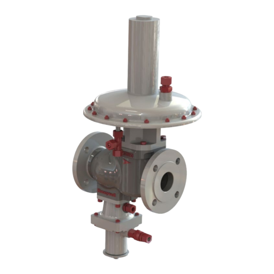
- Page 1 HON 380 gas pressure regulator with HON 673/674 controller User and maintenance instructions Spare parts...
-
Page 2: Table Of Contents
Performing maintenance on regulator unit RE1 8.6.2 Performing maintenance on regulator unit RE2 8.6.3 Performing maintenance on regulator unit RE0 Installing the regulator unit Maintaining the monitoring device Installing the controller 8.10 Completing the maintenance HON 380 gas pressure regulator with HON 673/674 controller... - Page 3 Additional information regarding spare parts 10.2 Spare parts kit for HON 380 with RE1 10.3 Spare parts kit for HON 380 with RE2 10.4 Spare parts kit for HON 380 with RE0 10.5 Lubricants HON 380 gas pressure regulator with HON 673/674 controller...
-
Page 4: General Considerations
About the safety notices 1.1 About this user manual Validity and purpose This user manual applies for gas pressure regulator HON 380 in combination with controller HON 673/674. This user manual provides all individuals with the information required for the safe handling in connection with the following tasks: ... -
Page 5: About The Safety Notices
Constructive changes The written approval from Honeywell Gas Technologies GmbH, Kassel, is required for any modifications and additions to the product. Any violation will void the legal liability for consequences arising thereof. - Page 6 CAUTION an accident may or will happen. minor or moderate bod- ily injury. Warnings about Warnings about possible material damages are identified with the word Attention material damages in this document. HON 380 gas pressure regulator with HON 673/674 controller...
-
Page 7: Description
2.1 Intended use Intended use The HON 380 direct-acting gas pressure regulator must be used and operated exclusively with a compatible controller made by Honeywell. The gas pressure reg- ulator is to be used in combination with a controller to provide a safety-shut off function in a regulating line. -
Page 8: Device Models
Description 2.2 Device models Gas pressure regula- The gas pressure regulator HON 380 in combination with a HON 673/HON 674 tor versions controller is available in a number of versions. There are different versions of the controller and of the regulator. -
Page 9: Labels/Markings
Small labels must be used to color-code and explicitly name the gas pressure reg- lines ulator’s connection lines (measuring lines and operating lines) based on what the lines are intended for and their minimum nominal size. HON 380 gas pressure regulator with HON 673/674 controller... -
Page 10: Identifying The Device
Make sure that the on-site conditions match the information on the nameplates nical specifications and the technical specifications. Technical specifications Locating the gas pres- The gas pressure regulator HON 380 type plate locations are as follows: sure regulator’s Figure Meaning nameplates... -
Page 11: Physical Design And Operation
2.5 Physical design and operation Figure The gas pressure regulator is made up of the following assemblies: Figure Description Regulator unit (RE): Body Controller - safety shut-off valve (SAV) HON 380 gas pressure regulator with HON 673/674 controller... - Page 12 Design of regulator Design of the regulator unit: unit RE2 Figure Meaning Spring adjuster Pilot spring GPR vent line connection GPR measuring line connection GPR comparator diaphragm Compensating diaphragm Valve spindle Valve plate HON 380 gas pressure regulator with HON 673/674 controller...
- Page 13 Connections of the gas pressure regulator: the HON 380 gas Figure Connection pressure regulator Vent line connection, regulator unit Measuring line connection, regulator unit Measuring line connection, SAV Vent line connection, SAV HON 380 gas pressure regulator with HON 673/674 controller...
- Page 14 The SAV can also be equipped with a manual or a remote release feature, as desired. It is also possible for it to be executed in functional class A (with dia- phragm rupture protection) or B (without diaphragm rupture protection). HON 380 gas pressure regulator with HON 673/674 controller...
-
Page 15: Technical Specifications
ASME B16.5 Pressure rating as per Class 150 = 20 bar Flange facing: Raised face DIN EN 1092-1 Pressure rating as per PN 16 = 16 bar Flange facing: B flange HON 380 gas pressure regulator with HON 673/674 controller... - Page 16 HON 380 dimensions The figures show schematic representations of the device’s structure. The dimen- sions for the different types can be taken from the table. Type DN 25 and DN 50 HON 380 gas pressure regulator with HON 673/674 controller...
- Page 17 ØH ØH ØH (in.) (in.) (in.) (in.) (in.) (in.) (in.) (in.) (in.) DN 25 (1″) (15.94) (4.13) (20.67) (4.13) (11.69) (9.84) DN 50 (2″) (16.14) (4.33) (21.65) (15.55) (4.33) (20.67) (4.33) HON 380 gas pressure regulator with HON 673/674 controller...
- Page 18 The device’s mechanical components do not contain any potential sources of ig- nition, and accordingly do not fall under the scope of ATEX 95 (94/9/EC). The electrical components used on the device meet all applicable ATEX requirements. HON 380 gas pressure regulator with HON 673/674 controller...
-
Page 19: Safety
In particular, you have no permission to modify or disable any safety contrivances. Adhere to the device maintenance intervals specified in this user manual. When replacing defective parts, only use original spare parts or manufac- turer-approved standard parts. HON 380 gas pressure regulator with HON 673/674 controller... -
Page 20: Requirements Concerning The Workforce, Personal Protective Gear, Workplaces
Knowledge with securing hau- ling distances Knowledge with the use of hoisting equipment Transportation per- Professional training and experi- Intra-company transport sonnel ence with the transport using stackers, etc. HON 380 gas pressure regulator with HON 673/674 controller... - Page 21 Disposal of the device rience with the disposal of pres- posal sure equipment and systems Knowledge of the relevant standards and regulations Ability to identify and avoid dangers autonomously HON 380 gas pressure regulator with HON 673/674 controller...
- Page 22 The workplaces for performing the various tasks are at the following locations: Task Workplaces Installation All around the device, depending on the task Start-up Set-up Maintenance, repairs Decommissioning HON 380 gas pressure regulator with HON 673/674 controller...
-
Page 23: Basics For Installing The Device In A Pipe
Blowdown line Following is the meaning of the acronyms: Acr. Meaning Nominal size of pipe Undisturbed length of pipe * Shut-off device with undisturbed flow pattern (ball valve) can be incorporated HON 380 gas pressure regulator with HON 673/674 controller... -
Page 24: Meter Run Characteristics
The nominal size of the pipe size is used is two standard nominal size min. 5 x DN increments larger HON 380 gas pressure regulator with HON 673/674 controller... - Page 25 If shut-off valves are used (reduced bore), the recommended distance down- stream of a measuring line is L min. 3 x DN. Gas meter pressure losses must be taken into account based on system con- ditions if applicable. HON 380 gas pressure regulator with HON 673/674 controller...
-
Page 26: Operating And Measuring Lines
Feedback line When using indirect acting (pilot-operated) slam-shut devices, the feedback line is used to return the outlet pressure to the actuator. HON 380 gas pressure regulator with HON 673/674 controller... -
Page 27: Transport And Installation
The hoisting equipment and slings must meet the following criteria: The load capacity must be sufficient for the gas pressure regulator’s weight. The hoisting height is adequate for the mounting position at the installation site. HON 380 gas pressure regulator with HON 673/674 controller... -
Page 28: Installing The Gas Pressure Regulator
The quantity and size are dependent on the following criteria: Design and size of the flange Assessing the Assess the installation situation. situation The numbers have the following meaning: Figure Meaning Flange gasket (not shown) Washer Screws HON 380 gas pressure regulator with HON 673/674 controller... - Page 29 Next task Proceed as follows: Installing the device connections (see page 30) HON 380 gas pressure regulator with HON 673/674 controller...
-
Page 30: Installing The Device Connections
Next task Proceed as follows: Checking the system for leaks (see page 31) HON 380 gas pressure regulator with HON 673/674 controller... -
Page 31: Checking The System For Leaks
Subjecting the device to pressure in the wrong direction may result in serious injury caused by bursting parts. Pressurize the system only on the inlet side. Details about the operating pressure can be found in the technical specifications. Technical specifications HON 380 gas pressure regulator with HON 673/674 controller... - Page 32 Proceed with step 4. Step Description Slowly close the inlet stop valve armature. Depressurize the inlet chamber and the outlet chamber. Seal the leaking pipe joints. Repeat the leak test starting with step 1. HON 380 gas pressure regulator with HON 673/674 controller...
-
Page 33: Adjusting The Settings Of The Device
15055028 15056078 Cream white 650 - 760 15055029 15056079 Gentian blue 750 - 800 10012564 10009164 Emerald green 790 - 900 15055030 15056081 Fire red 890 - 1000 15055031 10009165 black HON 380 gas pressure regulator with HON 673/674 controller... - Page 34 Turn the spring adjuster Clockwise (+) to tighten the pilot spring Counterclockwise (-) to loosen the pilot spring **RE2 and RE0 HON 380 gas pressure regulator with HON 673/674 controller...
- Page 35 If necessary, keep adjusting the set- ting of the spring adjuster until you get the right outlet pressure p Put the cap (1) back onto the dia- phragm housing. *) Only for RE1 versions *) RE1 HON 380 gas pressure regulator with HON 673/674 controller...
-
Page 36: Adjusting The Throttle Valve On The Measuring Line Of The Regulator Unit
(1) further in turn by turn while monitoring the regulator unit’s control behavior. Once you achieve the regulator unit response you want, stop changing the spindle’s position. Tighten the spacer nut. HON 380 gas pressure regulator with HON 673/674 controller... -
Page 37: Malfunctions
Check the gaskets for damage Diaphragm of the regulator Check the regulator unit’s dia- unit defective phragm for damage Leaks on the inside Valve plate is defective Check valve plate for damage HON 380 gas pressure regulator with HON 673/674 controller... - Page 38 The throttle valve setting is not Adjusting the throttle valve on correct the measuring line of the regu- lator unit (see page 36) HON 380 gas pressure regulator with HON 673/674 controller...
-
Page 39: Maintenance
Performing maintenance Performing maintenance on on regulator unit regulator unit (see page 47) Maintaining the monito- Perform maintenance on the ring device controller; see component doc- umentation included in delivery HON 380 gas pressure regulator with HON 673/674 controller... -
Page 40: Preparing For The Maintenance
The maintenance instructions below are provided as examples for the various gas instructions pressure regulator models and versions. Use the bills of materials to make sure that you replace all the maintenance parts relevant to your specific device model during maintenance. HON 380 gas pressure regulator with HON 673/674 controller... -
Page 41: Starting Maintenance
Close the inlet stop valve armature (1). Depressurize the gas pressure regulator. Open the ball valve (5) in the blowdown line (6) to discharge the pressure be- tween the inlet and the outlet valves. HON 380 gas pressure regulator with HON 673/674 controller... - Page 42 The regulator unit and the controller must be removed from the gas pressure regulator body. The gas pressure regulator, including the pipes, can remain in the gas regulating line. HON 380 gas pressure regulator with HON 673/674 controller...
-
Page 43: Removing The Regulator Unit
WARNING! Mortal danger associated with pressurized components. Removing the regula- Proceed as follows: tor unit from the body Figure Step Description Disconnect the connecting lines of the regulator unit (1) and (2). HON 380 gas pressure regulator with HON 673/674 controller... - Page 44 Remove the regulator unit from the body. Next task Depending on what you want to do next, proceed as indicated in the relevant sec- tion: Performing maintenance on regulator unit (see page 47) HON 380 gas pressure regulator with HON 673/674 controller...
-
Page 45: Dismounting The Controller
The system is not pressurized, see Starting maintenance (see page 41). WARNING! Mortal danger associated with pressurized components. Removing the control- Proceed as follows: ler from the body Figure Step Description Disconnect the connecting lines of the controller (1) and (2). HON 380 gas pressure regulator with HON 673/674 controller... - Page 46 Depending on what you want to do next, proceed as indicated in the relevant sec- tion: Perform maintenance on the controller; see component documentation Installing the controller (see page 62) HON 380 gas pressure regulator with HON 673/674 controller...
-
Page 47: Performing Maintenance On Regulator Unit
Take out the following parts: Spring adjuster (1) Bearing washer (2) Bearing collar (3) Bearing washer (4) Pilot spring (5) HON 380 gas pressure regulator with HON 673/674 controller... - Page 48 Axial needle roller bearing (2) Unscrew the nut (1) and take out the following parts: Washer (2) Centering cap (3) Support disc (4) **Version up to 1000 mbar HON 380 gas pressure regulator with HON 673/674 controller...
- Page 49 Unscrew the nut (1) and take out the check piece (2): Unscrew the screws (1). Take note of the gaskets (2) while doing so. Remove the diaphragm housing pot. Turn the component 180°. HON 380 gas pressure regulator with HON 673/674 controller...
- Page 50 Replace the two O-rings (2) with new, greased O-rings. Turn the nozzle assembly (1) and re- lease the locking ring (2) to remove the plain bearing (3). Check the plain bearing for damage. Replace it if necessary. HON 380 gas pressure regulator with HON 673/674 controller...
- Page 51 Depending on what you want to do next, proceed as indicated in the relevant sec- tion: Installing the regulator unit (see page 61) Completing the maintenance (see page 63) HON 380 gas pressure regulator with HON 673/674 controller...
-
Page 52: Performing Maintenance On Regulator Unit Re2
Spring plate (7) Pilot spring (8) Replace the O-ring (6) with a new, lu- bricated O-ring. Unscrew and remove the screws (1) and nuts (2) of the diaphragm hous- ing cover. HON 380 gas pressure regulator with HON 673/674 controller... - Page 53 **Version up to 1000 mbar Take out the following parts: Diaphragm plate (1) Rolling diaphragm (2) Check the rolling diaphragm for dam- age. Replace it if necessary. Grease the inner diaphragm bead. HON 380 gas pressure regulator with HON 673/674 controller...
- Page 54 Pressure piece (2) O-ring (3) Valve plate (4) Valve cone (5) O-ring (6) Replace the O-rings with new, greased O-rings. Release the circlip (1) on the marked recess. HON 380 gas pressure regulator with HON 673/674 controller...
- Page 55 Unscrew the nut (1) and take out the following parts: Pressure disc (2) Compensating diaphragm (3) Check the compensating diaphragm for damage. Replace it if necessary. HON 380 gas pressure regulator with HON 673/674 controller...
- Page 56 Depending on what you want to do next, proceed as indicated in the relevant sec- tion: Installing the regulator unit (see page 61) Completing the maintenance (see page 63) HON 380 gas pressure regulator with HON 673/674 controller...
-
Page 57: Performing Maintenance On Regulator Unit Re0
Replace the O-ring (6) with a new, lu- bricated O-ring. Unscrew and remove the screws (1) and nuts (2) of the diaphragm hous- ing cover. Take note of the washers (2) while doing so. HON 380 gas pressure regulator with HON 673/674 controller... - Page 58 Replace the O-ring (1) with a new, lu- bricated O-ring. Unscrew the screws (1) and remove the diaphragm housing pot (3). Take note of the gaskets (2) while doing so. Turn the component 180°. HON 380 gas pressure regulator with HON 673/674 controller...
- Page 59 Replace the two O-rings (2) with new, greased O-rings. Turn the nozzle assembly (1) and re- lease the locking ring (2) to remove the plain bearing (3). Check the plain bearing for damage. Replace it if necessary. HON 380 gas pressure regulator with HON 673/674 controller...
- Page 60 Depending on what you want to do next, proceed as indicated in the relevant sec- tion: Installing the regulator unit (see page 61) Completing the maintenance (see page 63) HON 380 gas pressure regulator with HON 673/674 controller...
-
Page 61: Installing The Regulator Unit
(2) in a criss-cross se- quence. Tightening torque: 20 Nm Reinstall all the pipes you removed previously on the regulator unit. Vent line (1) Measuring line (2) HON 380 gas pressure regulator with HON 673/674 controller... -
Page 62: Maintaining The Monitoring Device
If screws, bolts, or washers are replaced with identical new parts, any oil on these new parts must first be removed. Installing the control- Proceed as follows: ler in the body Figure Step Description Insert the controller into the body. HON 380 gas pressure regulator with HON 673/674 controller... -
Page 63: Completing The Maintenance
Do not twist the pipe connections in the assem- blies. Use a second spanner wrench for securing when loosening and tightening pipe joints. Next task Proceed as follows: Checking the system for leaks (see page 31) HON 380 gas pressure regulator with HON 673/674 controller... - Page 64 Apply an appropriate protective agent to assemblies at risk of corrosion. If stored correctly, O-rings and gaskets should not be kept longer than 7 years. Store the spare parts in the original package until they are used. HON 380 gas pressure regulator with HON 673/674 controller...
- Page 65 Close the inlet stop valve armature (1). Depressurize the gas pressure regulator. Open the ball valve (5) in the blowdown line (6) to discharge the pressure be- tween the inlet and the outlet valves. HON 380 gas pressure regulator with HON 673/674 controller...
- Page 66 Recycle elements made of synthetic materials. Dispose of any other components according to the quality of the materials. HON 380 gas pressure regulator with HON 673/674 controller...
- Page 67 Individual servicing parts can be ordered using the corresponding part num- ber, which is specified in the respective bill of materials for the regulator unit. The required number of parts is specified in the “Quantity” column. HON 380 gas pressure regulator with HON 673/674 controller...
- Page 68 Overview of bills of The bills of materials are subdivided as follows: materials Spare parts kit for HON 380 with RE1 Spare part drawing Maintenance and servicing parts Various spare parts kits, grouped by nominal size and pressure rat- ...
- Page 69 Appendix 10.2 Spare parts kit for HON 380 with RE1 Spare parts drawing for HON 380 with RE1 Version up to 300 mbar HON 380 gas pressure regulator with HON 673/674 controller...
- Page 70 Appendix Version for 300 - 1000 mbar Spare parts kits for HON 380 with RE1 DN 25 - DN 50 Series 380 spare parts kits - PN16/CL150 Part no. NBR version (standard) Name Qty. DN 25 DN 50 DN 50...
- Page 71 13.1 Noise abatement 10032774 10032775 10.3 Spare parts kit for HON 380 with RE2 Spare parts drawing for HON 380 with RE2 Version up to 300 mbar Version for 300 to 1000 mbar HON 380 gas pressure regulator with HON 673/674 controller...
- Page 72 Appendix NOTE: Item nos. not shown here are shown in the version of the regulating unit RE1. Spare parts kits for HON 380 with RE2 DN 50 Series 380 spare parts kits - PN16/CL150 Part no. NBR version (standard) Name Qty.
- Page 73 5.53 Locking ring DIN472 - 21 x 1 103845-RMK 2.53 Gasket A8 X 11.5 18710-RMK DN 80 - DN 100 Version up to 300 mbar Version for 300 to 1000 mbar HON 380 gas pressure regulator with HON 673/674 controller...
- Page 74 Appendix Spare parts kits for HON 380 with RE2 DN 80 - DN 100 Series 380 spare parts kits - PN16/CL150 Part no. NBR version (standard) Name Qty. DN 80 DN 100 Spare parts kit no. K380-011 K380-015 4.71 O-ring 2-160 W2.62 D133.02 20427 2.71...
- Page 75 Appendix 10.4 Spare parts kit for HON 380 with RE0 Spare part drawing RE0 DN 25 - DN 100 HON 380 gas pressure regulator with HON 673/674 controller...
- Page 76 Appendix Spare parts kits for HON 380 with RE0 DN 25 - DN 50 Series 380 spare parts kits - PN16/CL150 Part no. NBR version (standard) Name Qty. DN 25 DN 50 Spare parts kit no. K380-002 K380-007 4.71 O-ring 2-144 W2.62 D63.17 20513-RMK 0.71...
- Page 77 Appendix Spare parts kits for HON 380 with RE0 DN 80 - DN 100 Series 380 spare parts kits - PN16/CL150 Part no. NBR version (standard) Name Qty. DN 80 DN 100 Spare parts kit no. K380-012 K380-016 4.71 O-ring 2-160 W2.62 D133.02 20427 0.71...
- Page 78 Devices for oxygen Upper oxygen Important! Oil-free and pressure limit: Antiseize agent 28211 grease-free installation; only 260 bar at 60 °C antiseize agents are permis- sible Devices for ammonia Antiseize agent 28211 HON 380 gas pressure regulator with HON 673/674 controller...
- Page 79 Additional information To learn more about Honeywell’s prod- uct contact your Honeywell Process So- lutions representative, or visit www.hon- eywellprocess.com or www.hongas- tec.de. Honeywell Process Solutions...