Honeywell HON 5020 Assembly
Gas pressure regulator
Hide thumbs
Also See for HON 5020:
- User and maintenance manual (114 pages) ,
- User and maintenance manual (97 pages)

Related Manuals for Honeywell HON 5020


Summary of Contents for Honeywell HON 5020
- Page 1 Actuator assembly for HON 5020 Gas pressure regulator Component documentation, Maintenance manual and spare parts...
-
Page 2: Table Of Contents
Preparing for the maintenance Maintaining the actuator assembly Storage, removal, and disposal Storing the device Disassembling the device Disposing of the device Appendix Spare parts for the HON 5020 actuator assembly Spare parts for travel indication option Lubricants HON 5020 gas pressure regulator... -
Page 3: General Considerations
About the safety notices About this component documentation Validity and purpose This component documentation applies to the actuator assembly for HON 5020 gas pressure regulators. This component documentation provides all individuals with the information required in order to safely handle the device in connection with the following tasks: ... - Page 4 Constructive changes Changes and additions to the product must be approved by Honeywell Process Solutions in writing. Any violation will void the legal liability for consequences arising thereof. About the safety notices Meaning The information contained in the safety notices is intended to prevent personal injury.
- Page 5 CAUTION an accident may or will happen. minor or moderate bodily injury. Warnings about material Warnings about possible material damages are identified with the word Attention in this damages document. HON 5020 gas pressure regulator...
-
Page 6: Description
The HON 5020 actuator assembly must be used exclusively with a compatible pilot made by Honeywell. It is intended to be used, in combination with an appropriate pilot, as a gas pres- sure regulator in a regulating line. Depending on the pilot model used in combination with... -
Page 7: Labels/Markings
Make sure to always keep all relevant labels in good condition so that they will be easily legible. Immediately replace damaged and missing labels. Labels on the HON 5020 The following labels/markings can be found on the actuator assembly’s casing: actuator assembly... -
Page 8: Identifying The Actuator Assembly
Serial number of the device Valve seat diameter Device version (IS = version with integral overpressure protection) Standard (EN 334) Manufacturing date (month/year) Connection Temperature range Failure function (fail-open) Maximum allowable pressure Maximum allowable inlet pressure HON 5020 gas pressure regulator... -
Page 9: Layout And Operation
Maximum allowable inlet pressure Layout and operation In combination with an appropriate Honeywell pilot, the HON 5020 actuator assembly can be How it works used as a gas pressure regulator in order to maintain the outlet or inlet pressure of a gas constant within the regulating line, regardless of the influence of disturbance variables such as pressure changes and/or discharge changes. - Page 10 M 14 x 1.5 if the pilot being connected uses the metric system 3/8 NPT if the pilot being connected uses the imperial system Travel indication option The numbers have the following meaning: Figure Description Optical travel indicator Optical travel indicator with remote control HON 5020 gas pressure regulator...
-
Page 11: Technical Specifications
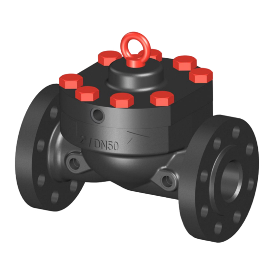
7.17 (182) 7.32 (186) 52.9 (24.0) 2″ (DN 50) 11.26 (286) 3.98 (101) 8.03 (204) 7.17 (182) 6.54 (166) 63.5 (28.8) 3″ (DN 80) 11.73 (298) 4.80 (122) 8.58 (218) 8.70 (221) 7.80 (198) 95.7 (43.4) HON 5020 gas pressure regulator... - Page 12 11.97 (304) 11.89 (302) 10.59 (269) 425.5 (193.0) *The HON 640a pilot used in this example weighs: 4.19 lbs (1.9 kg) Dimensions and weights for a HON 5020 body with expander as exam- Weight* Size Class inches (mm) inches (mm)
- Page 13 225.1 (102.1) 4''-8" 246.5 (111.8) 4''-8" 253.4 (114.9) 4''-8" 228.0 (103.4) 4''-8" 256.7 (116.4) 4''-8" 310.0 (140.6) 6''-12'' 402.0 (182.3) 6''-12'' 454.0 (205.9) 6''-12'' 481.1 (218.2) 6''-12'' 423.6 (192.1) 6''-12'' 479.1 (217.3) 6''-12'' 703.0 (318.8) HON 5020 gas pressure regulator...
- Page 14 -40 °F – +175 °F (-40 °C – +79 °C) Maximum temperature range ATEX specifications The mechanical components of the device do not have any potential ignition sources. Con- sequently, they are not subject to the requirements of the ATEX 95 Equipment Directive (94/9/EU). HON 5020 gas pressure regulator...
-
Page 15: Safety
Do not modify the device in any way, e. g. by removing parts or adding unapproved parts. In particular, you have no permission to modify or disable any safety contrivanc- When replacing defective parts, only use original spare parts or manufacturer-approved standard parts. HON 5020 gas pressure regulator... -
Page 16: Requirements Concerning The Workforce, Personal Protective Gear, Workplaces
Professional training and experience Mechanical Mechanical installation operating pressure equipment and fitter systems Knowledge of the relevant standards and regulations Ability to identify and avoid dangers autonomously HON 5020 gas pressure regulator... - Page 17 Start-up, operation (including partial), Protective clothing cleaning, maintenance, search and remedy Safety harness of errors Ear protection Safety boots with protection for electrostatic dis- charge (ESD) Safety goggles Safety gloves HON 5020 gas pressure regulator...
- Page 18 The workplaces for performing the various tasks are at the following locations: Task Workplaces Installation All around the device, depending on the task Start-up Set-up Maintenance, repairs Decommissioning HON 5020 gas pressure regulator...
-
Page 19: Transport And Installation
Chains The hoisting equipment and slings must meet the following criteria: The load-bearing capacity is adequate for the weight of the HON 5020. The hoisting height is adequate for the mounting position at the installation site. HON 5020 gas pressure regulator... - Page 20 Remove the protective caps. Install the ring bolts included in delivery and attach the slings to the ring bolts. Lift the HON 5020. Slowly and carefully transport the HON 5020 to the location where it will be installed. HON 5020 gas pressure regulator...
-
Page 21: Mounting The Actuator Assembly
Install the flange gaskets. Screw down the flange crosswise in the specified order. When doing so, make sure to observe the torques specified by the flange gaskets’ manufacturer. HON 5020 gas pressure regulator... -
Page 22: Checking The System For Leaks
Subjecting the device to pressure in the wrong direction may result in serious injury caused by bursting parts. Pressurize the system only on the inlet side. Details about the operating pressure can be found in the technical specifications. Technical specifications (see page 11) HON 5020 gas pressure regulator... - Page 23 Proceed with step 4. Step Description Slowly close the inlet stop valve armature. Depressurize the inlet area and the outlet area. Seal the leaking pipe joints. Repeat the leak test starting with step 1. HON 5020 gas pressure regulator...
-
Page 24: Maintenance
(e.g., when changing the pressure range). Spare parts that qualified personnel employed by the company operating the device is allowed to replace in the event of a fault or defect. HON 5020 gas pressure regulator... -
Page 25: Preparing For The Maintenance
Schematic diagram using the imperial system HON 640a as an example: The numbers have the following meaning: Meaning Inlet stop valve armature Gas pressure regulator Pressure gauge Outlet stop valve armature Valve for blowdown line Blowdown line HON 5020 gas pressure regulator... -
Page 26: Maintaining The Actuator Assembly
353 Nm (260 ft lbs) PN 25/40 Class 150 5/8″ UNC grade 7 6″ (DN 150) 203 Nm (150 ft lbs) PN 16 Class 300 3/4″ UNC grade 7 6″ (DN 150) 353 Nm (260 ft lbs) PN 25/40 HON 5020 gas pressure regulator... - Page 27 Push the lid down when unscrewing the screws. Remove the closing spring (1) and the diaphragm unit (2). Remove the flow restrictor. If the flow restrictor is damaged: Replace the flow restrictor with a new one. HON 5020 gas pressure regulator...
- Page 28 Refer to the additional tightening torque information at the beginning of this topic. Tighten the lid’s screws in a criss-cross sequence. Reinstall the pilot together with all the corresponding connecting pipes. HON 5020 gas pressure regulator...
-
Page 29: Storage, Removal, And Disposal
Before you start work- ing on these components: Close all connections leading to the gas-carrying line. Establish a depressurized status. Residual amounts of energy must be depressurized as well. HON 5020 gas pressure regulator... - Page 30 Use a second spanner wrench for securing when loosening and tightening pipe joints. Purging the lines with All the gas pressure regulator’s lines must be purged with nitrogen before the device is re- nitrogen moved. HON 5020 gas pressure regulator...
- Page 31 Dispose of the metals according to their types and grades (steel scrap, cast iron scrap, light alloy scrap, nonferrous heavy metal scrap, synthetic rubber scrap, electronic scrap). Recycle elements made of synthetic materials. Dispose of any other components according to the quality of the materials. HON 5020 gas pressure regulator...
-
Page 32: Appendix
Appendix Appendix Contents Topic Page Spare parts for the HON 5020 actuator assembly Spare parts for travel indication option Lubricants Spare parts for the HON 5020 actuator assembly Spare parts drawing for actuator assembly Maintenance and servic- Nominal size No. / Name Part no. - Page 33 Flow restrictor, 75% 204/MZ/016 Flow restrictor, 50% 204/MZ/012 Flow restrictor 25% 204/MZ/017 4″ Carrier plate 204/MN/002 4″ Metal foam 204/MF/001 Diaphragm 50/70 bar DP 10011307 6″ O-ring 730ODVN261 6″ Closing spring 10011249 6″ Screws 710BCFE03010 6″ HON 5020 gas pressure regulator...
- Page 34 Diaphragm, up to 70 bar DP 202/MJ/013 O-ring 730ODVN229 Nominal size No. / Name Part no. Letter 3″ 3" Class 150/300, PN 16/25/40 series 203/MS-006 5020 IGP spare parts kit Diaphragm, up to 50 bar DP 203/MJ/013 O-ring 730ODVN238 HON 5020 gas pressure regulator...
- Page 35 Diaphragm, up to 70 bar DP 204/MJ/004 O-ring 730ODVN244 Nominal size No. / Name Part no. Letter 6″ 6" Class 150/300/600, PN 16/25/40 206/MS-001 series 5020 IGP spare parts kit Diaphragm 50/70 bar DP 10011307 O-ring 730ODVN261 HON 5020 gas pressure regulator...
-
Page 36: Spare Parts For Travel Indication Option
Important! All parts must be slightly greased. Use the following lubricants: Components Lubricant Part no. O-rings Silicone grease 27 052 Diaphragm grip body All fastening screws Assembly lubricant 27 091 All fittings HON 5020 gas pressure regulator... - Page 37 Honeywell's integrated gas solutions can help you to better manage your gas assets and optimize your value chain. Additional information To learn more about Honeywell’s product contact your Honeywell Process Solutions representative, or visit www.honeywellprocess.com or www.hongastec.de. Honeywell Process Solutions...