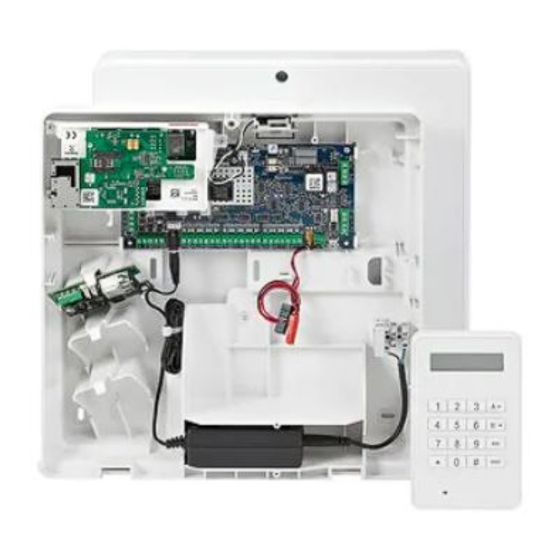
Honeywell Galaxy 2 Series Installation Manual
Hide thumbs
Also See for Galaxy 2 Series:
- Installation manual (118 pages) ,
- User manual (20 pages) ,
- Manual (2 pages)
Table of Contents
Advertisement
Quick Links
Advertisement
Table of Contents

Summary of Contents for Honeywell Galaxy 2 Series
- Page 1 Galaxy 2 Series Installation Manual Honeywell Security...
- Page 3 Galaxy 2 Series Installation Manual Table of Contents Contents SECTION 1: INTRODUCTION ..............1 Optional Peripherals ..................... 1 Features ........................2 RF ............................2 Groups ........................... 2 Dialler ............................. 2 SMS Text Messaging......................2 ProxKeypads ........................2 Remote Servicing ......................... 2 SECTION 2: QUICK GUIDE ................
- Page 4 Galaxy 2 Series Installation Manual Table of Contents Connecting the Galaxy 2 Series to the PSTN ............. 9 Private Branch Exchange (PBX) Approval ................ 9 REN and SEN Numbers...................... 10 SECTION 5: HARDWARE ................. 11 PCB Layout (2–44+) ..................... 11 PCB Layout (2–20) ....................
- Page 5 Galaxy 2 Series Installation Manual Table of Contents Peripherals - Installation, Wiring & Addressing..........24 Configuring ......................... 24 General ..........................24 Mk7 LCD Keypad/Keyprox ....................25 Keypad/Keyprox Installation ........................25 Mk7 Keypad/Keyprox Addressing ......................26 Adding a Mk7 Keypad/Keyprox to the System ..................26 Remote Input Output (RIO) ....................
- Page 6 Galaxy 2 Series Installation Manual Table of Contents SECTION 6: GENERAL OPERATION ............43 Galaxy 2 Series Users ..................43 Users ............................ 43 Engineers ..........................43 General Menu Operation..................43 Full Setting .......................... 44 Part Setting .......................... 44 Night Setting ........................45 Cancelling the Setting .......................
- Page 7 Galaxy 2 Series Installation Manual Table of Contents Removing Keytags or Cards - Mk7 485 Keyprox only ..................58 Removing Keytags or Cards - ECP 6160 Tags only .................... 58 Option 44 - Mobile Nos ..........................59 Option 47 - Remote Access ........................60 Option 48 - Level 3 Access ........................
- Page 8 Galaxy 2 Series Installation Manual Table of Contents SECTION 15: SPECIFICATIONS ............108 SECTION 16: COMPLIANCE AND APPROVALS........110 EN50131 Compliance....................... 110 Public Switched Telephone Network (PSTN) Approval ..........110 HONEYWELL SECURITY LIMITED WARRANTY ........111 Appendix A: Point ID Comms Triggers ..........A-1...
-
Page 9: Section 1: Introduction
SECTION 1: INTRODUCTION The Galaxy 2 Series is a 12-zone intruder alarm control panel. There are 2 variants. The 2-44+ is the full function version which is expandable to 44 zones. The 2-20 is an entry level version which is expandable to 20 zones. -
Page 10: Remote Servicing
PIN card is needed to set and unset the intruder alarm system. Remote Servicing The Galaxy 2 series control panel can be remotely and/or locally serviced by a Personal computer (PC). This is accomplished when the Remote Servicing Software is installed on the PC. -
Page 11: Section 2: Quick Guide
Default Engineer code: 112233 Menu Access Operation/Navigation Only valid codes can access the Galaxy 2 Series menu options. Type the code then press ent to access the menu. Data entry, on both ECP and RS485 keypads, is via the 0-9 function keys and the *, # on the keypad. -
Page 12: How To Restore An Alarm
Galaxy 2 Series Installation Manual Quick Guide (cont’d) How to Restore an Alarm Alarms, faults and tampers will be restored provided: 1. The cause has cleared 2. An authorised user PIN code or anti-code has been entered. 3. The conditions have been viewed on the keypad display after steps 1 and 2 above. -
Page 13: Section 3: System Architecture
2-way Voice (2-44+ only Power RIO (4) P026 * Only the first expander can be used on the 2-20 8 zones Twisted pair screened cable Belden 8723 equivalent. Daisy chain configuration only. RF Portal (2) Figure 1. Galaxy 2 Series System Configuration... -
Page 14: Section 4: System Wiring
Galaxy 2 Series Installation Manual System Wiring SECTION 4: SYSTEM WIRING General Information It is essential that this product is installed correctly, in particular with respect to a person’s safety and connec- tion to the mains electricity supply. This product is not suitable for installation, maintenance or connection by the user. -
Page 15: Zone And Data Cable Type
Illumination of the green power LED 2 indicates the presence of a.c. mains supply. The cover of the Galaxy 2 Series enclosure must be replaced whenever any connection to the BT master socket is completed to prevent exposure to potentially lethal voltages from the... -
Page 16: Equipment Electrical Rating
Galaxy 2 Series Installation Manual System Wiring (cont’d) Equipment Electrical Rating The control equipment is designed to operate on a mains supply of 230 Volts a.c. (230 V +10% -15%) at a frequency of 50 Hz. It is not suitable for other types of supply. The maximum current consumption in normal use is 200 mA. -
Page 17: Connecting The Galaxy 2 Series To The Pstn
Series, see Figure 3. Private Branch Exchange (PBX) Approval The Galaxy 2 Series may be used with some analogue PBX exchanges. The correct operation of the Galaxy 2 Series cannot be guaranteed under all possible conditions of connection to compatible PBXs. -
Page 18: Ren And Sen Numbers
Assume that all British Telecom equipment has a REN of one unless otherwise marked. More than one item of series apparatus may be connected to the Galaxy 2 Series ports marked phone. This is limited by summing the Series Equivalence Number (SEN) shown on each item of series connected apparatus, ensuring that the sum of the SENs is not more than one (1). -
Page 19: Section 5: Hardware
Galaxy 2 Series Installation Manual PCB Layout SECTION 5: HARDWARE PCB Layout (2–44+) LED2 Figure 4. Galaxy 2–44+ PCB Layout... -
Page 20: Pcb Layout
Galaxy 2 Series Installation Manual PCB Layout (cont’d) PCB Layout (2–20) 2-way header RS485 termination AC Power Input Extension Battery BATT + PROG HEADER Phone Terminals BATT - Output Power 12 Volt Phone Auxilliary LINE IN Line Output Input Trigger...


