Makita DCO180 Technical Information
Cordless cut-out tool
Hide thumbs
Also See for DCO180:
- Instruction manual (65 pages) ,
- Instruction manual (13 pages) ,
- Instruction manual (53 pages)
Advertisement
Quick Links
T
ECHNICAL INFORMATION
Models No.
DCO180, DCO140
Description
Cordless Cut-Out Tool
C
ONCEPT AND MAIN APPLICATIONS
Models DCO180/ DCO140 are cordless cut-out tools
powered by Makita 18V/14.4V Li-ion battery.
Their main benefits are:
• Lightweight design and ergonomic barrel grip makes
these products ideal for making outlet holes in drywall
at construction or renovation sites.
• High rotational speed of 30,000 min.
S
pecification
Specification
Voltage: V
Capacity: Ah
Energy capacity: Wh
Battery
Cell
Charging time (approx.):
Max output (W)
No load speed: min.
¹=rpm
ˉ
Collet capacity: mm (")
Stroke length of shoe plate: mm
[Distance from the end face of collet nut]
Overload protection
Soft start
Weight according to
EPTA-Procedure 01/2003: kg (lbs)
With BL1830, BL1840 or BL1850
*3
With BL1815, BL1815N or BL1820
*4
With BL1430, BL1440 or BL1450
*5
With BL1415 or BL1415N
*6
S
tandard equipment
Collet cone 3.18mm (1/8")
Drywall guide tip bit 3.18
Plastic carrying case
*7
Battery
*7
Charger
*7
Battery cover
*8
Plastic carrying case, battery and charger are not supplied with "Z" model.
*7
Supplied with the same quantity of extra Battery
*8
Note: The standard equipment may vary by country or model variation.
O
ptional accessories
1/8" shank cutting bits
• General purpose bit
• Drywall guide tip bit
• TC cement board bit
1/4" shank cutting bits
• Door and window casing bit
• TC cement board bit
Collet cone 6.35mm (1/4")
¹ for fast cutting
ˉ
Model
DCO180
18
1.3, 1.5, 2.0, 3.0, 4.0, 5.0
24, 27, 36, 54, 72, 90
15, 15, 24, 22, 36, 45
min.
with DC18RC
590
1.7 (3.7)
1.4 (3.1)
Battery BL1815
Battery BL1815N
Battery BL1820
Battery BL1830
Battery BL1840
Battery BL1850
W
Dimensions: mm (")
Length (L)
Width (W)
Height (H)
*1
*2
DCO140
14.4
1.3, 1.5, 3.0, 4.0, 5.0
19, 22, 44, 58, 72
Li-ion
15, 15, 22, 36, 45
with DC18RC
490
30,000
3.18 (1/8), 6.35 (1/4)
11.5 to 31.0
Yes
Yes
1.6 (3.4)
*3
1.4 (3.0)
*4
Battery BL1415
Fast charger DC18RC
Battery BL1415N
Charger DC18SD
Battery BL1415NA
Charger DC24SC
Battery BL1430
Automotive charger DC18SE
Battery BL1430A
Four port multi charger DC18SF
Battery BL1440
Battery BL1450
OFFICIAL USE
for ASC & Sales Shop
PRODUCT
P 1/ 8
L
H
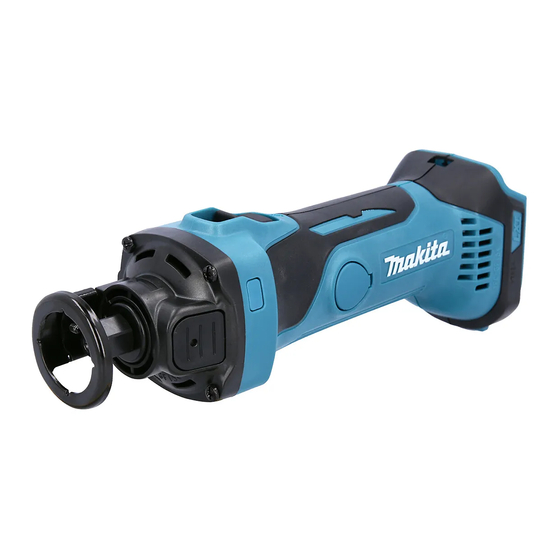
The image above is
Model DCO180.
DCO180
DCO140
296 (11-5/8)
/ 313 (12-3/8)
*1
77 (3)
118 (4-5/8)
100 (3-15/16)
With BL1815, BL1815N or BL1820/
BL1415 or BL1415N
With BL1830, BL1840 or BL1850/
BL1430, BL1440 or BL1450
*5
*6
*2
Advertisement

Related Manuals for Makita DCO180


Summary of Contents for Makita DCO180
- Page 1 P 1/ 8 Models No. DCO180, DCO140 Description Cordless Cut-Out Tool ONCEPT AND MAIN APPLICATIONS Models DCO180/ DCO140 are cordless cut-out tools The image above is Model DCO180. powered by Makita 18V/14.4V Li-ion battery. Their main benefits are: Dimensions: mm (") •...
-
Page 2: Necessary Repairing Tools
P 2/ 8 epair CAUTION: Repair the machine in accordance with “Instruction manual” or “Safety instructions”. [1] NECESSARY REPAIRING TOOLS Code No. Description Use for 1R027 Bearing setting pipe ø18-ø10.2 removing Ball bearing 6002DDW 1R029 Bearing setting pipe ø23-ø15.2 pressfitting Spindle complete 1R040 Armature holder 50 set for use with Vise removing Armature 1R165... - Page 3 P 3/ 8 epair [3] DISASSEMBLY/ASSEMBLY [2]-1. Armature (cont.) DISASSEMBLING (7) Receive the ribs (designated in gray color) of Bearing box complete with 1R258 or 1R040, and then push down Armature from Bearing box complete with 1R279 and Arbor press. (Figs. 6, 7 and 7A) Fig.
- Page 4 P 4/ 8 epair [3] DISASSEMBLY/ASSEMBLY [2]-1. Armature (cont.) ASSEMBLING Assemble by reversing the disassembly procedure. Note: • It is necessary to stop pressfitting Armature to set it in place in Bearing box complete. Therefore, use 1R383 as a stopper and pressfit Armature into Bearing box straight and carefullly while turning the Armature slowly to prevent the tilted insertion.
- Page 5 P 5/ 8 epair [3] DISASSEMBLY/ASSEMBLY Fig. 10 [2]-2. Bearing box complete 1R291 Spindle complete DISASSEMBLING (1) According to [2]-1, remove Armature. (Figs. 1 to 7) (2) Remove Retaining ring S-15 from Spindle complete with 1R291. (Fig. 10) (3) Receive Bearing box complete on 1R232, and then press down Spidle complete with 1R286 and Arbor press.
- Page 6 P 6/ 8 epair [3] DISASSEMBLY/ASSEMBLY [2]-2. Bearing box complete (cont.) DISASSEMBLING (7) Bearing box section is removed as drawn in Fig. 15. Fig. 15 Ball bearing 6002DDW Retaining ring Spindle complete R-32 Retaining ring S-15 Compression Bearing box Shaft lock spring 7 complete Fig.
-
Page 7: Circuit Diagram
1. Unscrew the two screws or disconnect the two receptacles. (If not, the Switch condition cannot be judged correctly because current flows through Controller.) 2. Check the condition between the terminals (shown below) with a tester (Makita part No. 1R402). Good condition... -
Page 8: Wiring Diagram
P 8/ 8 iring diagram Fig. D-2 Attach Receptacles to the tabs inside Switch. Do not pinch Lead wires connected to Switch Attach Insulated terminals to Switch as shown below. between the ribs on Housing L/R and Endbell complete. Switch Ribs on Housing L Ribs on Housing R Receptacle (2 pcs.)