Table of Contents
Advertisement
Quick Links
Advertisement
Table of Contents

Related Manuals for HIKVISION AE-VC222T-ITS


Summary of Contents for HIKVISION AE-VC222T-ITS
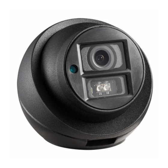
- Page 1 Vehicle-Mounted Camera User Manual UD02784B-A...
- Page 2 UserManual Thank you for purchasing our product. If there are any ques�ons, or requests, do not hesitate to contact the dealer. This manual applies to Vehicle-Mounted Camera. This manual may contain several technically incorrect places or prin�ng errors. The content is subject to change without no�ce, and the updates will be added to the new version of this manual.
- Page 3 disposed of as unsorted municipal waste in the European Union. See the product documenta�on for specific ba�ery informa�on. The ba�ery is marked with this symbol, which may include le�ering to indicate cadmium (Cd), lead (Pb), or mercury (Hg). For proper recycling, return the ba�ery to your supplier or to a designated collec�on point.
- Page 4 If smoke, odor or noise rise from the device, turn off the power at once and unplug the power cable, and then please contact the service center. If the product does not work properly, contact your dealer or the nearest service center. Never a�empt to disassemble the camera by yourself.
-
Page 5: Introduc�On
1 Introduc�on 1.1 Product Features This series of camera adopts new genera�on sensor with high sensi�vity and advanced circuit design technology. It features high resolu�on, low image distor�on and low noise, etc., which makes it suitable for monitoring system and image processing system. The main features are as follows: High performance CMOS sensor and high resolu�on bring high-quality image. -
Page 6: Installa�On
2 Installa�on Before youstart: Please make sure that the device in the package is in good condi�on and all the assembly parts are included. Make sure that all the related equipment is power-off during the installa�on. Check the specifica�on of the products for the installa�on environment. - Page 7 Figure 2-3 Take Out the Camera Step 4 Take 2 PA3X25 screws from the screw package and insert 2/3 of it into the expansion screws. Figure 2-4 Insert the Screws Step 5 Align the holes of the moun�ng base to the PA3X25 screws.
-
Page 8: Ptz Control
0 ~50° 0 ~360° Figure 2-7 3-axis Adjustment 3 PTZ Control The PTZ func�on is only supported in vehicle mounted TVI dome camera, you can realize the control of IR LED and mirror mode by calling presets. 3.1 IR LED Control Enable IR LED You can enable IR LED by calling preset No.