
Related Manuals for HIKVISION ColorVU DS-2CE Series


Summary of Contents for HIKVISION ColorVU DS-2CE Series
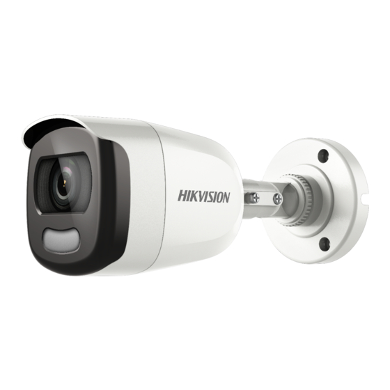
- Page 1 olorVu 2 MP Bullet and Turret Cameras User Manual 122919NA DS-2CE10DFT-F • DS-2CE10DFT-F28 DS-2CE12DFT-F • DS-2CE12DFT-F28 DS-2CE72DFT-F •DS-2CE72DFT-F28...
-
Page 2: Table Of Contents
Table of Contents Regulatory Information ..............3 FCC Information ................... 3 FCC Conditions ..................3 EU Conformity Statement ..............3 Industry Canada ICES-003 Compliance ..........4 Warning ....................4 Safety Instruction ................4 Warnings ....................4 Cautions ....................5 Mark Description ................. 5 1 Introduction ................... -
Page 3: Regulatory Information
User Manual Thank you for purchasing our product. If there are any questions or requests, do not hesitate to contact the dealer. This manual applies to the models below: Type Model DS-2CE10DFT-F Type I Bullet Camera DS-2CE10DFT-F28 DS-2CE12DFT-F Type II Bullet Camera DS-2CE12DFT-F28 DS-2CE72DFT-F Type I Turret Camera... -
Page 4: Industry Canada Ices-003 Compliance
harmonized European standards listed under the Low Voltage Directive 2014/35/EU, the EMC Directive 2014/30/EU, the RoHS Directive 2011/65/EU. 2012/19/EU (WEEE Directive): Products marked with this symbol cannot be disposed of as unsorted municipal waste in the European Union. For proper recycling, return this product to your local supplier upon the purchase of equivalent new equipment, or dispose of it at designated collection points. -
Page 5: Cautions
Input voltage should meet both the SELV (Safety Extra Low Voltage) and the Limited Power Source with 12 VDC according to the IEC60950-1 standard. Refer to technical specifications for detailed information. Do not connect multiple devices to one power adapter to avoid overheating or a fire hazard caused by overload. -
Page 6: Introduction
Introduction Product Features The main features are as follows: High Performance CMOS Sensor • Full Time Color • OSD Menu with Configurable Parameters • Auto White Balance • Internal Synchronization • Smart Light Mode • 3-Axis Adjustment • Overview This manual applies to two types of bullet camera and one type of turret camera. -
Page 7: Overview Of Type I Turret Camera
Overview of Type I Turret Camera Figure 3, Type I Turret Camera Overview Press and hold the switch button for five NOTE: seconds to switch the video output. Four kinds of video outputs are available: TVI, AHD, CVI, and CVBS. 3 Installation Before You Start Make sure that the device in the package is in good... - Page 8 Figure 2-1 Drill Template Drill the cable hole when using the ceiling NOTE: outlet to route the cable. 3. Attach the bracket to the ceiling/wall, and secure the camera with supplied screws. Figure 2-2 Affix Camera to Ceiling The supplied screw package contains self- NOTE: tapping screws and expansion bolts.
-
Page 9: Ceiling/Wall Mounting With Junction Box
1) Loosen the P screw to adjust the pan position [0° to 360°]. Tighten the screw after completing the adjustment. 2) Loosen the T screw to adjust the tilt position [0° to 180°]. Tighten the screw after completing the adjustment. 3) Loosen the R screw and rotate the camera [0°... -
Page 10: Installation Of Type Ii Bullet Camera
Junction Box Body Figure 7, Affix Junction Box to Wall/Ceiling 7. Route the cables through the bottom cable hole or the side cable hole of the junction box. Figure 8, Reattach Cover to Junction Box 8. Connect the junction box cover to its body. 2.1.1 Ceiling/Wall Mounting 9. -
Page 11: Ceiling/Wall Mounting With Junction Box
4. Fix the camera to the ceiling with supplied screws. Figure 10, Affix Camera to Ceiling The supplied screw package contains self- NOTE: tapping screws and expansion bolts. 5. For a concrete wall/ceiling, expansion bolts are required to fix the camera. For a wood wall/ceiling, self-tapping screws are required. -
Page 12: Installation Of Type I Turret Camera
Figure 12, Drill Template Drill the cable hole when using ceiling outlet NOTE: to route the cable. 3. Take apart the junction box, and align the screw holes of the bullet camera with those on the junction box’s cover. 4. Fix the camera on the junction box’s cover with three supplied screws. - Page 13 2) Pry the mounting base to remove the mounting base with the camera body with a flat object (e.g., a coin). Figure 15, Pry Open Mounting Base 2. Paste the drill template (supplied) to where you want to install the camera. 3.
-
Page 14: Ceiling/Wall Mounting With Junction Box
Figure 18, Secure Camera to Mounting Base 7. Connect the corresponding cables such as power cord and video cable. 8. Power on the camera to check whether the image on the monitor is at an optimum angle. If not, adjust the camera according to the figure below to get an optimum angle. - Page 15 3. Disassemble the junction box, and align the screw holes of the turret camera’s mounting base with those on junction box’s cover. 4. Fix the mounting base on junction box’s cover by supplied screws. Figure 21, Install Turret Camera’s Mounting Base Figure 22, Install Junction Box Body on Ceiling/Wall 5.
-
Page 16: Menu Description
Menu Description Follow the steps below to call the menu. The actual display may vary by camera model. NOTE: 1. Connect the camera to the TVI DVR and the monitor. Figure 23, Connections 2. Power on the camera, TVI DVR, and the monitor to view the image on the monitor. -
Page 17: Format
5. Click the direction arrow to control the camera. 1) Click up/down direction button to select the item. 2) Click Iris + to confirm the selection. 3) Click left/right direction button to adjust the value of the selected item. 3.1 FORMAT You can set the video format to 2 MP @ 25 fps or 2 MP @ 30 fps. -
Page 18: Video Settings
You can set the SLOW SHUTTER according to different light conditions. 3.1.4. VIDEO SETTINGS Move the cursor to VIDEO SETTINGS and click Iris+ to enter the sub-menu. WHITE BALANCE, BRIGHTNESS, CONTRAST, SHARPNESS, SATURATION, 3 DNR, and MIRROR are adjustable. Figure 26, Video Settings •... -
Page 19: Saturation
• SATURATION. Adjust this feature to change the color intensity. • 3 DNR (Digital Noise Reduction). The 3 DNR function can decrease the noise effect, especially when capturing moving images in poor light conditions, and deliver a more accurate and sharper image. •... -
Page 20: Motion
Figure 29, Privacy 1. Select a PRIVACY area. 2. Set the MODE as ON. 3. Click up/down/left/right button to define the position and the size of the area. • MOTION. In the user-defined motion detection surveillance area, the moving object can be detected and the alarm will be triggered.