Honeywell 7800 Series Manual
Relay module
Hide thumbs
Also See for 7800 Series:
- Product data (64 pages) ,
- Manual (56 pages) ,
- Installation instructions manual (40 pages)
Table of Contents
Advertisement
Quick Links
The Honeywell RM7885 is a microprocessor based inte-
grated burner control for semi-automatically fired gas, oil or
combination fuel single burner industrial applications. The
RM7885 requires a Relay Module Subbase and Amplifier to
complete the system. Options include Keyboard Display Mod-
ule, Personal Computer Interface, DATA CONTROLBUS
MODULE™, Remote Display Module, First-Out Expanded
Annunciator and COMBUSTION SYSTEM MANAGER™ Soft-
ware.
The RM7885 is programmed to provide a level of safety,
functional capability and features beyond the capacity of con-
ventional controls.
The RM7885 is adaptable to continuous firing, high-low or
modulating firing rate for semi-automatic burner sequencing.
Functions provided by the RM7885 include flame supervision,
system status indication, system or self-diagnostics and trouble-
shooting.
The RM7885 will operate with any of the following types of
ignitions:
1. Torch-ignited main burner using the S445A Start-Stop
Station, or any conventional knee or foot operated start-stop
station.
2. Torch-ignited pilot using the S445A Start-Stop Station, or
any conventional knee or foot operated start-stop station.
3. Direct-ignition oil burner or electrically ignited pilot,
using the S445A Start-Stop Station, which maintains electric
ignition as long as the Start Switch is depressed (up to 15
minutes).
Safety features:
- Closed loop logic test.
- Dynamic AMPLI-CHECK™.
- Dynamic input check.
- Dynamic safety relay test.
- Dynamic self-check logic.
- Expanded safe-start check.
- Internal hardware status monitoring.
- Tamper resistant timing and logic.
Lockout if Start Switch is held 15 minutes.
Access for external electrical voltage checks.
Application flexibility.
Communication interface capability.
Dependable, long-term operation provided by microcom-
puter technology.
First-out annunciation and system diagnostics are pro-
vided by an optional 2 row by 20 column Vacuum
Fluorescent Display (VFD) located on the optional Key-
board Display Module.
First-out expanded annunciation with 26 Light Emitting
Diodes (LEDs) for limits and interlocks (optional).
Five LEDs for sequence information.
Interchangeable plug-in flame amplifiers.
Local or remote annunciation of RM7885A operation and
fault information (optional).
Nonvolatile memory; RM7885A retains history files and
sequencing status after loss of power.
Remote reset (optional).
Report generation (optional).
Shutter drive output
Burner controller data (optional):
- Expanded annunciator status.
- Flame signal strength.
- Hold status.
- Lockout/alarm status.
7800 SERIES
Relay Module
- Sequence status.
- Sequence time.
- Total hours of operation.
- Total cycles of operation.
- Fault history providing the six most recent faults:
• Cycles of operation at the time of the fault.
• Expanded annunciator data at the time of the
fault.
• Fault message and code.
• Hours of operation at the time of the fault.
• Sequence status at the time of the fault.
• Sequence time at the time of the fault.
- Diagnostic information:
• Device type.
• Flame amplifier type.
• Flame failure response time.
• Manufacturing code.
• On/off status of all digital inputs and outputs.
• Software revision and release of RM7885A and
optional Keyboard Display Module.
CONTENTS
Specifications ................................................ 2
Ordering Information .................................... 2
Principle Technical Features ........................ 7
Safety Provisions ........................................... 8
Installation .................................................... 9
Wiring .......................................................... 11
Assembly ...................................................... 16
Operation .................................................... 19
Checkout ...................................................... 21
Troubleshooting .......................................... 29
L.Z. • 6-92 • © Honeywell Inc. 1992 • Form Number 65-0107
RM7885A
Advertisement
Table of Contents

Related Manuals for Honeywell 7800 Series


Summary of Contents for Honeywell 7800 Series
-
Page 1: Table Of Contents
Assembly ............16 Burner controller data (optional): Operation ............ 19 — Expanded annunciator status. Checkout ............21 — Flame signal strength. Troubleshooting .......... 29 — Hold status. — Lockout/alarm status. L.Z. • 6-92 • © Honeywell Inc. 1992 • Form Number 65-0107... -
Page 2: Specifications
Can also be 65 VA pilot duty with motorized valve, 1150 VA inrush, 460 VA open, 250 VA hold. Ordering Information When purchasing replacement and modernization products from your 7800 SERIES distributor, refer to the TRADELINE® Catalog for complete ordering number. - Page 3 Circuitry tests the flame signal amplifier at least 12 times a minute during burner operation and shuts down the burner if the amplifier fails. Order flame rod separately; see holder Instructions. Use only Honeywell Photocell, part no. 38316, ONLY. 65-0107...
- Page 4 RM7885A SPECIFICATIONS SEQUENCE TIMING FOR NORMAL OPERATION Device Initiate Standby Ignition RM7885A 10 sec. *STANDBY and RUN can be an infinite time period. **IGNITION is the time the Start Switch is pushed and limited to 15 minutes. APPROVAL BODIES: Communication Interface ControlBus Module—part Underwriters Laboratories Inc.
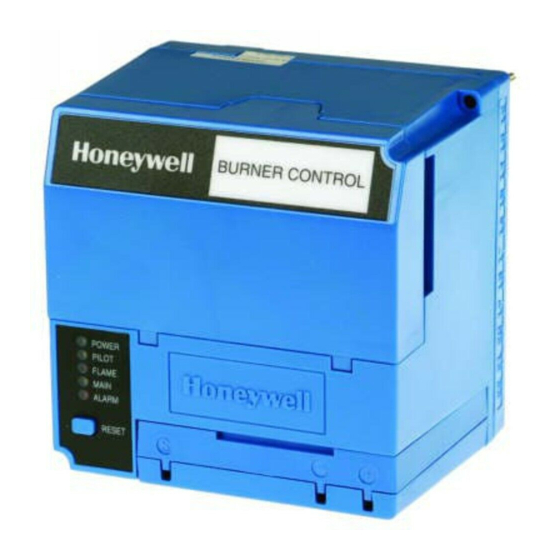
- Page 5 RM7885A SPECIFICATIONS Fig. 2—Mounting dimensions of RM7885A Relay Module and Q7800B Subbase in inches [millimeters]. BURNER CONTROL [127] POWER PILOT FLAME MAIN ALARM RESET [155] 5 [127] REMOVE ONLY FOR TERMINAL TEST ACCESS. M5149 Fig. 3—Rectification detectors. IGNITION ELECTRODE FLAME ROD (Q179C ONLY) CERAMIC INSULATORS...
- Page 6 RM7885A SPECIFICATIONS Fig. 4—Ultraviolet detectors. [105] 2 [51] 1/2-14 NPSM 4 [102] COLLAR WITH 6 FOOT [1.83 METER] 1–11-1/2 NPSM INTERNAL THREADS LEADWIRES (2) [89] INTERNAL THREADS [30] [27] [25] [38] 6 FOOT COLLAR WITH 1/2-14 NPSM [67] [1.83 METER] INTERNAL THREADS INSERTION DEPTH LEADWIRES (2) 3...
-
Page 7: Principle Technical Features
RM7885A SPECIFICATIONS • PRINCIPLE TECHNICAL FEATURES [300] 1 INCH NPT [198] [147] 15/16 [24] DIA. [55] [47] [158] [147] [64] [168] 1 [25] 15/16–18 UNC (2 EACH) 2 [51] M5084 C7076D Fig. 5—Infrared Detector. CELL MOUNT HEAT BLOCK [41] [70] [27] [32] [32]... -
Page 8: Safety Provisions
Keyboard Display shutdown occurs and all safety critical loads will be de- Module. See the 7800 SERIES System Annunciation Diag- energized. nostics and Troubleshooting, form 65-0118. -
Page 9: Installation
RM7885A INSTALLATION Installation WARNING 3. This equipment generates, uses and can radiate radio frequency energy and, if not installed and used in FIRE OR EXPLOSION HAZARD CAN accordance with the instructions, may cause interfer- CAUSE PROPERTY DAMAGE, SEVERE ence to radio communications. This equipment has INJURY, OR DEATH been tested and found to comply with the limits for a Verification of safety requirements must be per-... - Page 10 RM7885A INSTALLATION Fig. 6—RM7885A Internal block diagram. (See Fig. 7 for detailed wiring instructions.) (HOT) 120 Vac TEST FLAME SIGNAL JACK PLUG-IN FLAME MICROCOMPUTER AMPLIFIER TEST RESET PUSHBUTTON RELAY DRIVE CIRCUIT RELAY STATUS FEEDBACK AND LINE VOLTAGE INPUTS SAFETY RELAY CIRCUIT STATUS LEDs CONTROL...
-
Page 11: Wiring
RM7885A WIRING Wiring Refer to Fig. 7 for proper subbase wiring. Figures 8, 9, 10 or modulating motor from running in the high fire position and 11 show optional connections for the RM7885A. before the manually opened safety-shutoff valve is opened, a Fig. - Page 12 RM7885A WIRING Fig. 8—High-low or modulating burner diagram. Q7800 DPST ALARM SILENCING SWITCH 120V ALARM R482B S445A START-STOP STATION STOP LIMITS INTERNAL FUEL JUMPER PRESSURE INTERMITTENT SWIITCH PILOT START CONTROLLER MANUAL VALVE LOW FIRE MOTOR END SWITCH IGNITION HI-LO OR RECTIFYING FLAME R W B MODULATING...
- Page 13 RM7885A WIRING Fig. 9—Cascading two or more burners or supervising two or more pilots when required for safe ignition of one burner. Q7800 Q7800 DPST ALARM DPST ALARM (L1) (L1) SILENCING SILENCING SWITCH SWITCH 120 ALARM 120 ALARM S445A S445A START-STOP START-STOP STATION...
- Page 14 RM7885A WIRING Fig. 10—Dual fuel with high-low or modulating burner. Q7800 PILOT MOTOR DPST ALARM (L1) SILENCING GANGED 3 POLE SWITCH DOUBLE THROW SWITCH 120V ALARM R482B R482B S445A START-STOP STATION STOP LIMITS INTERNAL JUMPER START IGNITION FUEL FUEL PRESSURE PRESSURE SWITCH SWITCH...
- Page 15 RM7885A WIRING Fig. 11—RM7885A wiring with R4155 alarm silencing relay. Q7800 ALARM R4155A S445A START-STOP STATION STOP LIMITS INTERNAL JUMPER INTERMITTENT PILOT START MAIN FUEL VALVE(S) IGNITION RECTIFYING FLAME ROD, RECTIFYING (HOT) PHOTOCELL, OR INFRA- RED (LEAD SULFIDE) MASTER FLAME DETECTOR SWITCH C7027A, C7035A, OR BLUE...
-
Page 16: Assembly
RM7885A WIRING • ASSEMBLY 5. Recommended grounding practices: leadwires: a. Use the earth ground to provide a connection be- 1. Do not run high voltage ignition transformer wires tween the subbase and the control panel or the in the same conduit with the flame detection wiring. equipment. - Page 17 RM7885A ASSEMBLY INSTALLING PLUG-IN FLAME SIGNAL Fig. 13—Wall or burner installation. AMPLIFIER 1. Disconnect the power supply before beginning instal- lation to prevent electrical shock and equipment damage. More than one disconnect may be involved. 2. Align the amplifier circuit board edge connector with the keyed receptacle on the RM7885A.
- Page 18 SENSOR WHITE EARTH GROUND BROWN SHUTTER C7076A C7076D SHUTTER TERMINAL BLOCK ULTRAVIOLET (C7027/C7035/C7044) L1 (HOT) L2 (COMMON) BLUE 7800 SERIES WHITE SOLID STATE SELF-CHECKING SOLID STATE ULTRAVIOLET (C7012E,F) ULTRAVIOLET (C7012A,C) BLUE BLUE YELLOW YELLOW WHITE WHITE BLACK BLACK BLACK BLACK...
-
Page 19: Operation
RM7885A OPERATION Operation NORMAL START-UP Sequence of Operation When the Start Switch is pressed, the Ignition Trans- The operating sequence for the RM7885A follows, see former is energized and power is applied to terminal 10 of the Figs. 17, 18, and Table 3. RM7885A. - Page 20 RM7885A OPERATION Fig. 18—Sequence status LEDs. CAPTIVE MOUNTING SCREW DUST COVER SEQUENCE RELAY STATUS MODULE LEDs FLAME RESET AMPLIFIER PUSHBUTTON FLAME FLAME CURRENT SIMULATOR INPUT TEST JACKS M8995 TABLE 3—LED SEQUENCE STATUS DISPLAY INFORMATION. Burner Sequence LEDs Energized INITIATE POWER, PILOT, FLAME, MAIN and ALARM STANDBY POWER, PILOT, FLAME, MAIN and ALARM STANDBY HOLD: F/G...
-
Page 21: Checkout
RM7885A OPERATION • CHECKOUT tors, valves, transformers, motors and other devices as re- continuing the checkout. quired. 10. After completing each test, be sure to remove the test 9. Obtain normal operation for each required test before jumper(s). TABLE 4—STATIC CHECKOUT. Test Test Normal... - Page 22 1. Wiring connections are correct and all terminal If an RM7885A is replaced with a lower or higher screws are tight. functioning 7800 SERIES Relay Module, the burner 2. Flame detector(s) is clean, installed and positioned will not sequence unless wiring changes are made.
- Page 23 RM7885A CHECKOUT FLAME SIGNAL MEASUREMENT TABLE 6—FLAME SIGNAL. Acceptable Maximum Flame Flame signal Steady dc Expected Detector Amplifier Voltagea Dc voltage Flame Rod R7847A,B 1.25 Vdc 5.0 Vdc at the Photocell Keyboard Display C7012A,C Module C7012E,F R7847C C7015A R7848A,B C7027A R7849A,B C7035A 5.0 Vdc at a...
- Page 24 RM7885A CHECKOUT ment manufacturer, close the manual main fuel shutoff from the burner inlet, or disconnect power from the automatic valve(s). main fuel valve(s). 9. Let the RM7885A run with the pilot only for a couple 3. Close the master switch. Allow ten seconds for the minutes to allow time for purging unburned fuel from the RM7885A to complete the INITIATE Test.
- Page 25 RM7885A CHECKOUT e. Make burner adjustments for flame stability and NOTE: Low fuel pressure limits, if used, could be open. If so, input rating. bypass them with jumpers during this check. f. Shut down the system by pressing the Stop Switch. Make sure the burner flame goes out and make sure 1.
- Page 26 RM7885A CHECKOUT If hot refractory saturation occurs, the condition must 10. Restart the system and increase the pilot flame size be corrected. Add an orifice plate in front of the cell to by increasing its fuel flow until a smooth main flame is restrict the viewing area.
- Page 27 RM7885A CHECKOUT (ALL FLAME RODS) PILOT TURNDOWN TEST Test to be sure that a false signal from a spark ignition (ALL INSTALLATIONS USING A PILOT) system is not superimposed on the flame signal. Perform this check on all installations that use a pilot. The Ignition interference can subtract from (decrease) or add purpose of this test is to verify that the main burner can be lit to (increase) the flame signal.
- Page 28 Infrared radiation from a hot refrac- tory is steady, but radiation from a flame has a flickering NOTE: The Honeywell Q624A Solid State Spark Generator characteristic. The infrared detection system responds only will prevent detection of ignition spark when properly to flickering infrared radiation;...
-
Page 29: Troubleshooting
RM7885A CHECKOUT • TROUBLESHOOTING d. Shutdown will occur after 15 minutes. within .8 or 3 seconds (depending on the FFRT of 3. Loss of flame during RUN. the amplifier) after the flame goes out. a. Open the pilot and main fuel manual shutoff e. - Page 30 RM7885A TROUBLESHOOTING TABLE 6—SEQUENCE AND STATUS HOLD INFORMATION. NOTE: Normal sequences are in bold type, while abnormal sequences are not in bold type. Sequence Explanation INITIATE The LED indicates the burner status, POWER, which is a stabilization period for the RM7885A to check for any fluc- tuations in AC line voltage inputs or control input on power- up or during normal operation.
- Page 31 RM7885A TROUBLESHOOTING TABLE 6—SEQUENCE AND STATUS HOLD INFORMATION (continued). NOTE: Normal sequences are in bold type, while abnormal sequences are not in bold type. Sequence Explanation The LEDs indicate the burner status, POWER, PILOT, FLAME and MAIN, which is entered when the Start Switch is released.
- Page 32 Home and Building Control Home and Building Control Helping You Control Your World Honeywell Inc. Honeywell Limited—Honeywell Limitée 1985 Douglas Drive North 740 Ellesmere Road Golden Valley, Minnesota 55422 Scarborough, Ontario M1P 2V9 QUALITY IS Printed in U.S.A.