Advertisement
Quick Links
T
ECHNICAL INFORMATION
Model No.
Description
C
ONCEPT AND MAIN APPLICATIONS
Model JR100D (RJ01
10.8V cordless recipro saws; JR100D (RJ01
while JR102D is equipped with Blade clamp for both Recipro saw and Jig saw blades.
Their advantages are:
• Toolless blade clamp for Recipro saw blade (model JR100D [RJ01
• Blade clamp compatible with both Recipro saw and Jig saw blades (model JR102D only)
• Compact and lightweight handy body for comfortable operation
• Multi-position switch enables various grip position for versatile operations.
These products are available in the following variations.
Model No.
type
JR100DZ
BL1013
(Li-ion 1.3Ah)
JR100DWE
RJ01Z
RJ01ZW
BL1014
(Li-ion 1.3Ah)
RJ01
RJ01W
JR102DZ
BL1013
(Li-ion 1.3Ah)
JR102DWE
All models also include the accessories listed below in "Standard equipment".
S
pecification
Model No.
Cell
Voltage: V
Battery
Capacity: Ah
Energy capacity: Wh
Charging time (approx.): min.
Strokes per minutes: min.
Length of stroke: mm (")
Capacity: mm (")
Blade clamp type
Jig saw blade compatibility
Switch lock
Electric brake
Variable speed control by trigger
LED job light
Weight according to EPTA-Procedure 01/2003: kg (lbs)
*1: Model number for North and Central American countries except Mexico and Guam
*2: for North and Central American countries except Mexico and Guam
S
tandard equipment
JR100D (RJ01
)
*1
[All countries]
Recipro saw blade 100mm (for wood) .... 1
Recipro saw blade 100mm (for metal) .... 1
Note: The standard equipment for the tool shown above may vary by country.
O
ptional accessories
Charger DC10WA (DC10WB for North and Central American countries except Mexico and Guam)
Battery BL1013 (BL1014 for North and Central American countries except Mexico and Guam)
Recipro saw blades, Jig saw blades (for JR102D only)
JR100D (RJ01
)/ JR102D
*1
10.8V Cordless Recipro Saw
*1: Model number for North and Central American countries
except Mexico and Guam
)/ JR102D are compact and lightweight
*1
) is equipped with Toolless blade clamp
*1
Battery
Charger
quantity
No
No
2
DC10WA
No
No
DC10WB
2
No
No
2
DC10WA
¹= spm (strokes per minute)
ˉ
Wood
Pipe: Ø
JR102D
[All countries except Sweden, Finland, Estonia]
Recipro saw blade 100mm (for wood) ....... 1
Recipro saw blade 100mm (for metal) ....... 1
Hex wrench 3 .............................................. 1
] only)
*1
Plastic
Hex
Housing
carrying case
wrench
No
No
Makita-blue
Yes
Makita-blue
No
No
Makita-blue
Yes
No
No
Yes
Makita-blue
Yes
JR100D (RJ01*
10.8
50 with DC10WA, (DC10WB
Toolless
No
1.2 (2.6)
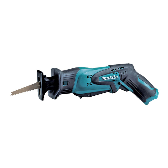
PRODUCT
W
H
L
(Drawn above is
Model JR100D.)
Dimensions: mm (")
Length (L)
Width (W)
Height (H)
146 (5-3/4)
Offered to
color
All countries except North and
Central American countries
(Mexico & Guam are included.)
North and Central
white
American countries
except Mexico and Guam
white
All countries except North and
Central American countries
(Mexico & Guam are included.)
JR102D
)
1
Li-ion
(10.8/12Vmax
)
*
,
2
1.3
14
)
*
2
0 - 3,300
13 (1/2)
50 (2)
50 (2)
Hex wrench is required.
Yes
Lock-off
Yes
Yes
Yes
1.1 (2.5)
JR102D
[Sweden, Finland, Estonia]
Jig saw blade B-10 (for wood) .... 1
Jig saw blade B-18 (for wood) .... 1
Jig saw blade B-24 (for metal) .... 1
Hex wrench 3 ............................... 1
P 1/ 12
355 (14)
63 (2-1/2)
Advertisement

Related Manuals for Makita RJ01 1 Series


Summary of Contents for Makita RJ01 1 Series
- Page 1 Housing Model No. Charger Offered to type quantity carrying case wrench color JR100DZ All countries except North and BL1013 Makita-blue Central American countries (Li-ion 1.3Ah) JR100DWE DC10WA (Mexico & Guam are included.) RJ01Z Makita-blue North and Central RJ01ZW BL1014 white American countries (Li-ion 1.3Ah)
-
Page 2: Necessary Repairing Tools
1R281 Round Bar for Arbor 7-50 removing Ball bearing 6902ZZ from Gear housing [2] LUBRICATION Apply Makita grease N. No.2 to the following portions designated with the black triangles to protect parts and product from unusual abrasion. Item No. Description... - Page 3 P 3/ 12 epair [3] DISASSEMBLY/ASSEMBLY [3] -1. Slider (cont.) DISASSEMBLING Fig. 2 2. Remove Housing (R) by unscrewing 3x16 Tapping screws (8pcs). 1. Remove Set plate before removing Housing (R) 3x16 Tapping screws (8pcs). small slotted screwdriver Housing (R) Set plate Housing (L) Fig.
- Page 4 P 4/ 12 epair [3] DISASSEMBLY/ASSEMBLY [3] -1. Slider (cont.) DISASSEMBLING Fig. 5 6. Remove Gear housing by 7. Remove Plate by unscrewing 8. Remove Slider, Slider guide unscrewing M4x14 Pan head M4x14 Pan head screws and Sponge seal. screws (3pcs). (2pcs).
- Page 5 P 5/ 12 epair [3] DISASSEMBLY/ASSEMBLY [3] -1. Slider (cont.) ASSEMBLING (3) Assemble Gear housing cover to Gear housing (Fig. 8). Fig. 8 6. Set the following parts to the nearest point to the 7. Assemble Gear housing cover to Gear DC Motor side as illustrated below.
-
Page 6: Gear Complete
P 6/ 12 epair [3] DISASSEMBLY/ASSEMBLY [3] -2. Gear complete DISASSEMBLING (1) Disassemble Housing (R) from Housing (L) and remove Gear housing section from Housing (L) (Fig. 2, 3, 4.) (2) Remove Gear housing from Gear housing cover (Fig. 5 (3) Put Gear housing on 1R258 and remove Gear complete with Arbor press (Fig. - Page 7 P 7/ 12 epair [3] DISASSEMBLY/ASSEMBLY [3] -3. Toolless Blade Holder Section (Model JR100D) DISASSEMBLING (1) Disassemble Housing (R) from Housing (L) and remove Gear housing section from Housing (L) (Fig. 2, 3). (2) Remove Shoe from Gear section by unscrewing M4x10 Countersunk head screws (Fig. 3). (3) Disassemble Toolless blade holder section (Fig.
- Page 8 P 8/ 12 epair [3] DISASSEMBLY/ASSEMBLY [3] -3. Toolless Blade Holder Section (Model JR100D) (cont.) ASSEMBLING (2) Do further step for Assembling in the order of Fig. 14, 15, 16, 17, 18. Fig. 14 3. Mount Guide sleeve to Blade guide. 4.
- Page 9 P 9/ 12 epair [3] DISASSEMBLY/ASSEMBLY [3] -3. Toolless blade holder section (Model JR100D) (cont.) ASSEMBLING (1) Assemble Blade guide to Slider in case Blade guide is removed from Slider (Fig. 9). Fig. 17 90° 8. Hold Gear housing with vise and grip Connecting sleeve Driving sleeve with Water pump pliers over a cloth so as not to damage it.
- Page 10 P 10/ 12 epair [3] DISASSEMBLY/ASSEMBLY [3] -4. Switch lever F complete DISASSEMBLING (1) Disassemble Housing (R) (Fig. 2). (2) Remove Switch lever section from Housing (L) and disassemble it as drawn in Fig. 19. Fig. 19 1. Remove Switch lever unit; 2.
-
Page 11: Circuit Diagram
P 11/ 12 ircuit diagram Fig. D-1 Color index of lead wires' sheath Black White Terminal Switch DC Motor Line filter unit (for the countries where suppression of Radio interference is regulated) Connector iring diagram Fig. D-2 Wiring of LED Lead wire (Before setting DC Motor and Gear housing) Store the extra portion of Lead wires in this space designated Fix the Lead wires in these... - Page 12 P 12/ 12 iring diagram (cont.) Fig. D-3 Fig. D-4 Wiring to DC Motor Wiring to Terminal Assemble DC Motor to Housing (L), * the Lead wires must be faced to Housing (R) side. Connect the Lead wires to * the Lead wire (black) must be located to the Switch trigger side. Terminal as drawn below.