
Related Manuals for Casio JD-4000


Summary of Contents for Casio JD-4000
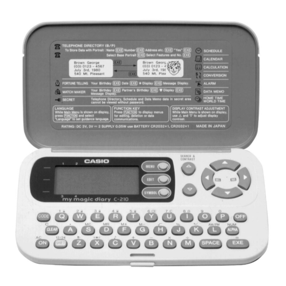
- Page 1 (without price) JD-4000 (ZX-805B, D) C-210 (ZX-805C) FEB. 1995 JD-4000 C-210 INDEX...
-
Page 2: Table Of Contents
CONTENTS SCHEMATIC DIAGRAM....................1 SPECIFICATIONS ......................3 GENERAL GUIDE ......................6 RESET OPERATIONS ....................9 BATTERY REPLACEMENT ..................11 ERROR MESSAGE ..................... 13 LSI PIN FUNCTION ..................... 14 OPERATION CHECK ....................16 TO SAVE THE DATA TO ANOTHER MACHINE ............17 TROUBLESHOOTING .................... -
Page 3: Schematic Diagram
1. SCHEMATIC DIAGRAM NOTES: 1. DP1, DP2, and DP3 are the checking points for the power supply. 2. CP50, CP51, CP52, and DP1 are the terminals for the data transfer. 3. The other terminals marked with may be used to function checking. 4. -
Page 4: Specifications
2. SPECIFICATIONS Telephone Directory Mode Storage and recall of telephone directory data (name, telephone number, portrait). Includes secret memory area and auto sort function. Schedule Mode Storage and recall of appointments (month/date/hour/minute, description). Includes secret memory area and auto sort function. Data Memo Mode Storage and recall of memos (memo name, memo). - Page 5 General Display: Liquid crystal display Memory Capacity: 4,096 bytes Power Supply: Main batteries – One lithium battery (CR2032) Back-up battery – One lithium battery (CR2032) Power Consumption: 0.03 W Battery Life*: Main batteries – • approximately 400 hours continuous operation •...
- Page 6 Mode Bytes per Data Item Telephone Directory (name) + (telephone number) + 15 Schedule (description) + 12 Data Memo (memo name) + (memo contents) + 3 Examples: Telephone Directory data only When all items use 10 characters for the name and 12 characters for the phone number, you can store approximately 110 items.
-
Page 7: General Guide
• Never use strong liquid cleaners such as lacquer thinner or benzine to clean the unit. • In no event will CASIO or its suppliers be liable to you or any other person for any damages, including any incidental or consequential expenses, lost profits, lost savings, or any other dam- ages arising out of the use of this product. - Page 8 3. While the icon you want is highlighted, press EXE to enter its mode. Setting the System Language The JD-4000/C-210 can display messages in any one of five languages: English, Spanish, Italian, German, and French. To set the system language 1.
- Page 9 To Switch the Key Input Tone On or Off 1. Press MENU to display MENU 2. 2. Use , and to highlight , and then press EXE to enter the Alarm Mode. 3. While the currect alarm time setting is shown, press (C) to display the "Key Tone".
-
Page 10: Reset Operations
4. RESET OPERATIONS Use the following operation to reset the unit and clear its memory. Important! • Be sure to reset the unit before using it for the first time. • Do not use a very sharp pencil to press the RESET button. Doing so can damage the unit. To reset the unit 1. - Page 11 When the unit does not work properly ... The unit may stop working properly after it is subjected to strong electrostatic charge or strong impact. If this happens, first check to make sure that the main battery and back-up battery are cor- rectly installed, and then perform the following operation.
-
Page 12: Battery Replacement
5. BATTERY REPLACEMENT Low Battery Warning The message, "Low battery" appears whenever battery power drops below a certain level (about 2.70 V). Replace the main battery immediately after this message appears. Whenever the low battery warning message appears, the OFF key will be the only function that works. - Page 13 To replace the main battery 1. Switch power off. 2. Loosen the screw that holds the battery compartment cover in place, and then remove the cover(Fig. 1). * Do not turn switch on until you complete step 7 of this procedure. 3.
-
Page 14: Error Message
6. ERROR MESSAGE Message Meaning Action Check Time! Always appears when RESET Confirm that the current time operation is aborted. setting is correct. Memory Full! Memory is full. Reduce number of characters in data being stored, or delete unneeded data from memory. No Record! No data stored in memory. -
Page 15: Lsi Pin Function
7. LSI PIN FUNCTION 1. CPU (HC3009-01-F1) Pin No. Signal In/Out Function DUMMY Not used 2 ~ 9 IO0 ~ 7 In/Out Data bus CS6B0 Chip enable signal for ROM CS7B0 Chip enable signal for RAM DUMMY Not used WEB0 Write enable signal for RAM OEB0 Output enable signal for RAM and ROM... - Page 16 Pin No. Signal In/Out Function 109, 110 S1, S2 Not used 111 ~ 205 S3 ~ 96 Segment signal for display DUMMY Not used 207, 208 XI, XO In/Out Clock terminal (DT-26S) DUMMY Not used 210, 211 PO, PI In/Out Main clock terminal (3.45MG) DUMMY Not used...
-
Page 17: Operation Check
8. OPERATION CHECK Notes: (1) Please save all data stored in the unit to another unit by using the method described in section 9 before starting this check program, because the data will be corrupted by this operation. (2) The TEST operation shown below is defined as the short-circuit operation mentioned in section 9. -
Page 18: To Save The Data To Another Machine
9. TO SAVE THE DATA TO ANOTHER MACHINE It is commonly necessary to save all data stored in the customer's unit before repairing it. For this purpose, you can transfer the data of the JD-4000 or C-210 unit to another unit using the following procedure. - Page 19 (3) To do data transfer Please switch both the units on, and make them enter the MENU1 mode. Thus you may start to transfer the all data of customer’s unit to the receiving unit following the procedure shown below. MENU 1 MENU 1 TEST Over 2 seconds...
- Page 20 Main battery Shortcircuit the two shorting pads with a shorting pin for over 2 seconds. Shorting pin Shorting pads — 19 —...
-
Page 21: Troubleshooting
10. TROUBLESHOOTING 1. Intermittent display START Is the Heat seal defective ? Replace Is the battery contact weak ? Clean and adjust pressure of contact Are there short circuit around the pins Resolder of the LSI (HC3009-01-F1) ? Is the soldering weak ? Resolder Replace the PCB ass'y 2. - Page 22 3. No display START Is the battery contact weak? Clean and adjust pressure of contact Is the battery switch contact weak? Clean and adjust pressure of contact Is the AC key contact weak? Clean or replace the rubber key Are there short circuit around Resolder the pins of the LSI? Check or replace the electrolytic...
-
Page 23: Exploded View
11. EXPLODED VIEW DISASSEMBLY 1. Loose the screw Q, then remove the battery cover P. 2. Remove the two lithium batteries. 3. Loose the four screws S, then remove the lower cabinet R. 4. Loose the four screws H, then remove the PCB ass'y 8. LSI1... -
Page 24: Parts List
A : JD-4000 (Blue case) B : JD-4000 (Green case) 12. PARTS LIST C : C-210 FOB Japan Quantity Item Code No. Parts Name Specification N.R.Yen A B C Unit Price PCB ASS'Y C1,18,31 6414 4420 Capacitor CB0220141T3 C11,12 6511 7570 Chip capacitor... - Page 25 FOB Japan Quantity Item Code No. Parts Name Specification N.R.Yen A B C Unit Price 6414 4980 Hard case FC1L8051067 6413 4480 Hard case FC1L8051024 6413 4490 Hard case FC1L8051041 6414 4990 Accessory case FC1L8051075 6413 4510 Accessory case FC1L8051032 6413 4520 Accessory case FC1L8051059 6413 4180 Switch knob...
- Page 26 8-11-10, Nishi-Shinjuku Shinjuku-ku, Tokyo 160, Japan Telephone: 03-3347-4926...