Casio CASSIOPEIA A-20 Service Manual & Parts List
Handheld personal computer
Hide thumbs
Also See for CASSIOPEIA A-20:
- Getting started manual (23 pages) ,
- Getting started manual (23 pages) ,
- Getting started (23 pages)
Table of Contents
Advertisement
Advertisement
Table of Contents

Related Manuals for Casio CASSIOPEIA A-20


Summary of Contents for Casio CASSIOPEIA A-20
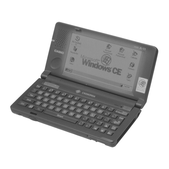
- Page 1 (without price) Handheld Personal Computer A-20 (ZX-340) DEC. 1997 A-20...
-
Page 2: Table Of Contents
CONTENTS HARDWARE SPECIFICATIONS -------------------------------------------------------------- 1 General Specifications ------------------------------------------------------------------- 1 Electrical Specifications----------------------------------------------------------------- 2 ACCESSORIES ------------------------------------------------------------------------------------ 3 OPTIONS --------------------------------------------------------------------------------------------- 3 SYSTEM CONFIGURATION -------------------------------------------------------------------- 4 GENERAL GUIDE --------------------------------------------------------------------------------- 5 ADJUSTING DISPLAY CONTRAST --------------------------------------------------------- 6 DESKTOP COMPUTER SYSTEM CONFIGURATION ---------------------------------- 7 SETTING UP ---------------------------------------------------------------------------------------- 7 REPLACING BATTERIES ----------------------------------------------------------------------- 9 To replace the main batteries---------------------------------------------------------- 9 To replace the backup battery------------------------------------------------------- 10... - Page 3 POWER SUPPLY CIRCUIT ------------------------------------------------------------------- 35 Primary Circuit---------------------------------------------------------------------------- 35 5 V Circuit ---------------------------------------------------------------------------------- 36 3 V Circuit ---------------------------------------------------------------------------------- 37 PCMCIA Circuit --------------------------------------------------------------------------- 38 LCD power Circuit ----------------------------------------------------------------------- 39 Voltage Line ------------------------------------------------------------------------------- 40 DETECTOR CIRCUIT --------------------------------------------------------------------------- 41 DIAGNOSTIC PROGRAM --------------------------------------------------------------------- 42 Introduction-------------------------------------------------------------------------------- 42 OPERATION CHECK --------------------------------------------------------------------------- 43 IrDA Communication Test ------------------------------------------------------------ 48 Current Consumption and Voltage Detectors Check ------------------------ 50...
-
Page 4: Hardware Specifications
HARDWARE SPECIFICATIONS General Specifications Model: A-20 640 × 240 dots/0.24 dot pitch, FSTN LCD, 4 grayscale monochrome Display: CPU: Memory RAM: 8M bytes ROM: 8M bytes Speaker: Sound Interfaces: RS-232C: 115.2K BPS Data communication jack PC card slot CompactFlash card slot Infrared port (IrDA compatible protocol) Communication distance: 10 to 70 cm Maximum Speed: 115.2K BPS... -
Page 5: Electrical Specifications
Electrical Specifications Current Consumption (V-in: 2.6 V ± 0.1 V, LCD Contrast VR: MID.): Main Battery: Diagnostics Program with alkaline batteries 80 MHz: 650 mA or under Sleep: 50 mA or under Standby: 1.4 mA or under 450 µA Back-up Battery: OFF: Voltage Detectors: 2.0 V ±... -
Page 6: Accessories
ACCESSORIES • A-20 Unit • Stylus • Dummy Card • RS-232C Cable The stylus is inserted into the CASSIOPEIA. The dummy card is inserted in the CASSIOPEIA. • CD-ROM (two) • Manuals (Hardware Manual, User’s Guide) • AA-size Alkaline Batteries (two) •... -
Page 7: System Configuration
SYSTEM CONFIGURATION Note that CASSIOPEIA will not operate under AC adapter power alone if its main batteries are not loaded. AC adapter CASIO Digital Camera Data communication cable (SB-62) Infrared port CASSIOPEIA Desktop Computer Printer CompactFlash Card PC Card CD-ROM... -
Page 8: General Guide
GENERAL GUIDE • Infrared port For infrared commu- • Touch screen nication Displays text data and operational indica- tors, as well as icons that can be operated using the stylus. • Data communication jack For connection of a digital camera or other external equipment. -
Page 9: Adjusting Display Contrast
• Battery holder • Battery holder release Holds main batteries Slide to release the battery holder to remove (AA-size alkaline). it, or to secure the battery holder in place. • Backup battery compartment Holds the backup battery (CR2032). • Card cover (CompactFlash card) •... -
Page 10: Desktop Computer System Configuration
DESKTOP COMPUTER SYSTEM CONFIGURATION The computer configuration described below is required to support the installer and the software applica- tions contained on the Microsoft CD-ROM supplied with the CASSIOPEIA. • Microsoft Windows NT Workstation 4.0 or Windows 95 (U.S. version) •... - Page 11 Important • Should the display lock up or go blank at this time, first perform the full reset (page 12). If this does not correct the problem, remove the main batteries from the CASSIOPEIA and then remove the back-up battery. Wait for about five minutes, and then perform this procedure again, starting from step 1. Be sure that the positive (+) and negative (–) poles of the batteries are facing correctly when you reload them into the CASSIOPEIA.
-
Page 12: Replacing Batteries
REPLACING BATTERIES The CASSIOPEIA has a dual power supply that consists of main batteries and a backup battery. Be sure to load the main batteries and a back-up battery before using the CASSIOPEIA for the first time after purchas- ing it. Also, replace batteries as soon as possible after they start to get weak. Important! •... -
Page 13: To Replace The Backup Battery
5. Reattach the battery holder to the CASSIOPEIA. • The battery holder will emit a click and the battery holder release will automatically lock when the battery holder is securely in place. To replace the backup battery 1. Make sure the CASSIOPEIA is turned off. •... -
Page 14: Reset
RESET You should reset the CASSIOPEIA whenever it stops working or whenever some other operational problem has caused it to malfunction. To reset the CASSIOPEIA 1. Press the RESET button with the stylus. • This automatically turns off CASSIOPEIA power. 2. -
Page 15: Full Reset
FULL RESET Perform the full reset when you want to clear all memory contents and settings because memory contents are corrupted, because you have forgotten the security code, or for any other reason. Important The following procedure deletes all data in memory. Be sure to save any important data contents you may need later to a computer disk or other medium. -
Page 16: Connecting To A Desktop Computer
CONNECTING TO A DESKTOP COMPUTER Use the following procedure to connect the CASSIOPEIA to a desktop computer. Note that exchanging data with a desktop computer requires Microsoft Windows CE Services, which is on the Microsoft CD-ROM that is included with the CASSIOPEIA. Requirements RS-232C cable (supplied with CASSIOPEIA) To connect to a desktop computer... -
Page 17: Replacing The Pc Card
REPLACING THE PC CARD The CASSIOPEIA comes equipped with a PC card slot that supports memory, modem and other PC cards*. * Use only PC cards that are compatible with the CASSIOPEIA. Important • Be sure to keep the dummy card that comes with the CASSIOPEIA inserted in the card slot whenever you are not using a PC card. -
Page 18: Replacing The Compactflash Card
REPLACING THE COMPACTFLASH CARD The CASSIOPEIA comes equipped with a card slot that supports CompactFlash cards. Important • If the card stops part way into the slot, do not try to force it. Doing so can damage the card or the CASSIOPEIA. -
Page 19: Connecting To External Equipment
You can connect external equipment to the data communication connector. You can also use special soft- ware to set up the CASSIOPEIA to exchange image data with a CASIO digital camera. See the documentation that comes with the software for details. -
Page 20: Memory Backup / Restore
MEMORY BACKUP / RESTORE Make the backup copy by Windows CE Services to your PC before repairing A-20, and restore the data from PC to user’s A-20 after repairing. For the details of Backup/Restore, refer to the operation manual of Windows CE Services. Notes: 1* Backup program of Windows CE Services back up only files and databases. - Page 21 6. Click “Full: back up all data” and “Back Up Now”. 7. Confirm the file name of bakup copy and then click “OK”. Backup starts. — 18 —...
-
Page 22: Restore
Restore Execute Restore after repairing. 1. Turn on the user’s A-20 and then Welcome wizard appears. 2. Execute touch panel calibration and then skip other setups after calibration. 3. Connect repaired A-20 to your PC with RS-232C cable. 4. Start Windows CE Services on your PC. 5. - Page 23 7. Restoring starts. 8. Click “OK”. — 20 —...
-
Page 24: Block Diagram
BLOCK DIAGRAM 10 M 32.768 K PLL X4 80 MHz SH-7093 (IC1) RAM 8 Mbyte HM51W16165 (RAM5~RAM8) CompactFlash Card ROM 8Mbyte Memory Slot (U301~U305) PCMCIA Audio Amp. Card MC34119 (IC9) LCD unit 3.68M Mini Jack L C D IrDA IrDA Transceiver Gate Array CIM-10S EL Driver... -
Page 25: Device Features
TLB supports 1K/4K bytes page,128 entries. 8K bytes Cash. Interrupt Controller. User Break Controller. Bus State Controller. Watch Dog Timer. CASIO proprietary RTC. 2K bytes Mask ROM. ON Controller. 1 ch Serial I/F. 1 ch Serial I/F with 16 bytes FIFO. 1 channel Reload Timer. - Page 26 115.2 kbaud. IrDA 0 - 1 m. 9-pin RS232C ±12 V I/F. 3-pin Serial Port CASIO proprietary serial interface to Casio’s digital cameras and electric orga- nizerand so on. Up to 38.4 kbaud. 0 to +5 V I/F. Dead Man’s Switch ‘Manual Reset’...
-
Page 27: Lsi/Ic Data
LSI/IC DATA SH-7093 (CPU / IC1) N o . Pin Name I o / O u t Function To/From Data bus Data bus Data bus Data bus D23/Port 7 Data bus +3.3V source D22/Port 6 Data bus D21/Port 5 Data bus D20/Port 4 Data bus D19/Port 3... - Page 28 N o . Pin Name I o / O u t Function To/From Address bus +3.3V source Address bus Address bus Address bus Address bus Address bus Address bus Address bus +3.3V source Address bus Address bus Address bus Vss (PLL) GND for PLL CAP1 Capacitor connecting terminal for PLL...
- Page 29 N o . Pin Name I o / O u t Function To/From CASHHB / CAS2HB D31-D24 / D15-D8 select signal BGA288,ROM Board CASHLB / CAS2LB D23-D16 / D7-D0 select signal BGA288,ROM Board +3.3V source WE1B D15-D8 select signal BGA288 WE0B D7-D0 select signal BGA288,LCD uint,ROM Board...
-
Page 30: Mb87A915 (Gate Array/Ic3)
MB87A915 (Gate Array/IC3) N o . Pin Name V o l t I o / O u t Function To/From CFCE1B CE signal for CompactFlash card CompactFlash card IOPORT0 Not used IOPORT1 I/O Port 1 LCD unit V5D3 Data bus PCMCIA CARD Voltage detect for PCMCIA PCMCIA CARD... - Page 31 N o . Pin Name V o l t I o / O u t Function To/From V5D0 Data bus PCMCIA CARD V5A0 Address bus PCMCIA CARD VDD1 +5V source V5D8 Data bus PCMCIA CARD V5D1 Data bus PCMCIA CARD V5D9 Data bus PCMCIA CARD...
- Page 32 N o . Pin Name V o l t I o / O u t Function To/From KBOUT7 Key common signal Keyboard KBOUT6 Key common signal Keyboard KBOUT5 Key common signal Keyboard KBOUT4 Key common signal Keyboard KBOUT3 Key common signal Keyboard KBOUT2 Key common signal...
- Page 33 N o . Pin Name V o l t I o / O u t Function To/From LOCK Not used MEMCLB Not used Address bus Address bus Address bus Address bus Address bus Address bus Address bus Address bus Address bus Address bus Address bus Address bus...
- Page 34 N o . Pin Name V o l t I o / O u t Function To/From STATUS0 STATUS0 signal from CPU 244 ONSTATUSB ONSTATUS signal from CPU CE2B CE2B signal from CPU CE2A CE2A signal from CPU VDD2 +3V source ON circuit start signal to CPU RDWRB Read/Write signal from CPU...
-
Page 35: Mc34119 (Ic9)
MC34119 (IC9) V CC (Top View) MAX3241CAI (IC5) VCC=3 V 0.1 µf to 5.5 V C2– C1– MAX3241 V– MAX3241 V– R1IN C2– R2IN T1IN T1OUT R3IN T2IN T2OUT R4IN SHON RS-232 LOGIC OUTPUTS INPUTS R5IN R1OUTB T3IN T3OUT T1OUT R2OUTB R1OUTB T2OUT... -
Page 36: Upd42S16160Lg5
UPD42S16160LG5 A0 to A11 : Address Inputs I/O 1 to I/O 16 : Data Inputs/Outputs : Row Address Strobe UCAS : Column Address Strobe (upper) LCAS : Column Address Strobe (lower) : Write enable : Output enable : Power Supply : Ground : No Connection RN5VD18CA (IC113) -
Page 37: Max608 (Ic105,Ic106)
MAX608 (IC105,IC106) DIP/SO AGND SHDN (Top View) EMI FILTER ARRAY UPD23C32000LGY — 34 —... -
Page 38: Power Supply Circuit
POWER SUPPLY CIRCUIT The power supply circuit consists of 5 blocks which are Primary circuit, 5 V circuit, 3 V circuit , PCMCIA power circuit and LCD power circuit as follows; PCMCIA PCMCIA power circuit 5V circuit 5 V system Fuse Primary Alkaline... -
Page 39: Circuit
5 V Circuit DC/DC converter MAX608ESA (IC105) generates +5.11 V and it makes up 5 V system. VIO : +5 V source for 3-pin jack and LCD power block. BATDTCT: It distinguishes alkaline and Li-ion to change the load according to the battery. When alkaline is used, it is H. -
Page 40: Circuit
3 V Circuit DC/DC converter MAX608ESA (IC106) generates +3.77 V and it makes up 3 V system. V3MAIN : The reference voltage for the detector. V3SYS : +3.4 V source for IC1,IC3,IC5. V3RAM : +3.4 V source for DRAM (RAM5 ~ RAM8). V3ROM : +3.4 V source for ROM (U301,U302). -
Page 41: Pcmcia Circuit
PCMCIA Circuit DC/DC converter MAX1651 (IC111) generates 3.4 V VEL : 5.11 V source for LCD unit. PEL : Controls ON/OFF of VEL. From pin 160 of MB87A915 (IC3). VPC : 3.4 V or 5.11 V source for detecting PCMCIA power. PSEL5 : Power supply select signal for PCMCIA (H=5 V, L=3 V). -
Page 42: Lcd Power Circuit
LCD power Circuit DC/DC converter RN5VH3 (IC201) generates LCD power and it makes up LCD power system for LCD. VDD : +3.7 V source for LCD unit. VAMP : +7.0 V source for LCD unit. PLCD : Controls ON/OFF of VAMP. From pin 159 of MB87A915 (IC3). VLCD+: +15.5 V source for LCD unit. -
Page 43: Voltage Line
Voltage Line U301/U302 RAM5~8 BGA288 SH-7093 32M-MASK ECSTOJY106R MAX3241 MC34119 CIM-10S GATE ARRAY D-RAM RS232C AudioIC IRIC V3AUD V3RAM V3SYS V3ROM V3IRDA VCRDIF VCARD VLCD+ VLCD– Connector Connector Connector Connector RS-232C LCD unit PCMCIA 3P Jack — 40 —... -
Page 44: Detector Circuit
DETECTOR CIRCUIT The detector circuit consistes of 7 blocks as follows; 1 : VDETECTOR1 (Alkaline and Li-ion) 5 : Full charge detector 2 : VDETECTOR2 (Alkaline and Li-ion) 6 : 3V detector (AC adaptor is not used) 3 : Backup battery detector 7 : PCMCIA voltage detector 4 : AC Adaptor detector VDETECTOR 1... -
Page 45: Diagnostic Program
DIAGNOSTIC PROGRAM Introduction The following steps must be followed before diagnostics. START Remove Main and Backup batteries Load main Make sure that Battery Holder Release batteries switch is on “NORMAL OPERATION” side. Press ON Display appear? Press RESET button and then Display appear? Replace batteries with... -
Page 46: Operation Check
OPERATION CHECK Preparation 1 : A-20 5 : AC-adapter 2 : Alkaline batteries 6 : Charger 3 : Jigs of RS-JIG-232C and RS-JIG-3PIN 7 : Rechargeable battery pack 4 : RAM Card XC-110 8 : Diagnostic program (Diag 340.EXE) Notes: • Be sure to keep separate back-up copies of all important data in A-20, because the DISGNOSTICS make data corrupt. - Page 47 Step Operation Display Note To continue the inspection Boot inspection program. ** Main Menu ** you must make the task 0 AUTO MODE bar disappear. When 1 DISPLAY there is a task bar on the 2 TOUCH PANEL bottom of the display 3 MEMORY press Ctrl + Esc to make 4 SERIAL...
- Page 48 Step Operation Display Note Space, Alt + <, Alt + > Check variable resistor. ** Main Menu ** 0 AUTO MODE Check if display bright- 1 DISPLAY ness is changeable. 2 TOUCH PANEL 3 MEMORY 4 SERIAL 5 POWER CONTROL 6 AUDIO 7 OTHERS 8 AUTO MENU1...
- Page 49 Step Operation Display Note Inspection of Auto-hide function. Touch four points 1 4 as shown in the left. NG if no sound is heard. Enter, 3 ** Memory ** 1 ROM CHECK SUM 2 ROM BUS CHECK ROM1=059a ROM2=059a ROM3=*** Enter ** Memory ** 1 ROM CHECK SUM...
- Page 50 Step Operation Display Note Make sure backup battery VDETS is installed. Remove backup battery VDETS Put backup battery back in Press battery notification Recharge Release battery notifica- Recharge tion SW. Plug in AC adapter. AC Adapter USED Install lithium battery Green LED lights.
-
Page 51: Irda Communication Test
IrDA Communication Test Prepare 2 units and place them as follows; A-20 ±15 deg. A-20 A-20 A-20 10 cm 80 cm UNIT-1 UNIT-2 Step Note Operation Display Operation Display IrDA ** Main Menu ** ** Main Menu ** AUTO MODE AUTO MODE DISPLAY DISPLAY... - Page 52 UNIT-1 UNIT-2 Step Note Operation Display Operation Display ENTER Make sure H HHHHHHHHHHHHHHHHH <Infrared SEND/RECEIVE> display stops HHHHHHH 1 Send data (MAX Baudrate) 2 Receive data(MAX Baudrate) 3 Send data (MIN Baudrate) 4 Receive data(MIN Baudrate) ENTER <Infrared SEND/RECEIVE> <Infrared SEND/RECEIVE> 1 Send data (MAX Baudrate) 1 Send data (MAX Baudrate) 2 Receive data(MAX Baudrate)
-
Page 53: Current Consumption And Voltage Detectors Check
Current Consumption and Voltage Detectors Check Prepare the following items; 1 : Power supply 1 unit 2 : Ammeter 1 unit 3 : Voltmeter 1 unit 4 : AC adapter 1 unit 5 : Charger 1 unit Current Consumption Check Step Operation Display (Wiring) - Page 54 Step Operation Display (Wiring) Note Main (Power off) Current consumption at Battery OFF. at OFF Measure the current. Ib = 1.4 mA or under Backup 1 : Turn the power off. Connect the items as Backup battery terminal battery 2 : Supply the voltage to shown.
-
Page 55: Voltage Detectors Check
Voltage Detectors Check Check the following detectors; Low battery message detector for alkaline batteries.(2.0 V ± 1 %) VDET1: Foced power off detector for alkaline batteries.(1.6V ± 1 %) VDET2: Low battery message detector for rechargeable battery.(3.3 V ± 2 %) VDET1R: Foced power off detector for rechargeable battery.(3.0 V ±... - Page 56 Step Operation Display (Wiring) Note Setting Change to connect power Connect the items as Rechargeable battery terminal supply to the terminals for shown. rechargeable battery. Vr = 2.6 V A-20 AC adapter Charger VDET1R Put power supply voltage Measure the voltage that VDET1R down by degrees.
-
Page 57: Disassembly • Assembly
DISASSEMBLY • ASSEMBLY 1. Module 1. Remove dummy card and stylus. 2. Remove the backup battery cover by pressing a point with the stylus shown below, then remove the backup battery. 3. Remove the main batteries by releasing the lever. 4. -
Page 58: Upper Case Ass'y
7. Remove the connecter in the main battery campartment leading from the backup battery compartment by pulling it straight up. Caution:Pulling the wire may cause the pins and hooks to break. 8. Separate upper case and lower case. 2. Upper case ass’y 1. - Page 59 4. Unscrew two screws (30) to remove the terminal holders. Remove both battery terminal. Terminal holder 5. Remove the terminal wire, then remove the main board. 6. When you replace K-film (35), stick K-spacer (34) on the “ON” key on new K-film. * This is to prevent from accidentaly turning the computer off.
-
Page 60: Removal Of Touch Panel And Lcd Unit
3. Removal of touch panel and LCD unit * Removal is possible without removing the main board. 1. Unscrew two screws (25), then remove hinge holder (24). Hinge holder 2. Set the lower case with diplay facing up and unscrew six screws (2). 3. - Page 61 5. Remove three screws (56) from the hinge on tilt unit side then open the diplay at an angle of about 45 degrees and slide it sideways. 6. Remove the hinges and place the cases flat as shown below. 7. Hold two FPCs togother and roll them up as shown below. 8.
- Page 62 Slide the shaft piece (55) to the direction of the arrow to remove it. 10. Remove seven screws (56) and screw (49) , then remove LCD unit. Caution:When doing so do not touch the TAB shown by the arrows below. (To prevent open circuits which cause no display) Do not touch Do not touch...
-
Page 63: Precautions When Installing Lcd Unit
14. Remove the connector on microphone board, then remove the LCD unit. 4. Precautions when installing LCD unit. 1. Do not touch the TAB of the display. (To prevent open circuits) — 60 —... -
Page 64: Installation Of Shaft Piece
5. Installation of shaft piece 1. Roll up the FPC of the display around on a precision screwdriver. 2. Pass FPC through an opening on the bottom of shaft piece (55). 3. Pass FPC through inside of shaft piece then through an opening on the top of shaft piece. 4. -
Page 65: How To Pass Fpc Through The Upper Case
6. How to pass FPC through the upper case 1. Place upper case with keyboard side facing up above the display which is also facing up. 2. Hold two FPCs togother and roll them up as shown below. 3. Let the upper case stand and pass the rolled up FPCs through the hole. 4. -
Page 66: Precautions When Assembling
5. Pull to the point where the FPC is bent 90 degrees. Then move the upper case so that the FPC will go through the hole. 6. Pull the FPC all the way. 7. Precautions when assembling 1. Speaker and backup battery both are connected by 2-pin connectors. The connector closer to the hinge are for the backup battery. - Page 67 4. Before putting the upper case and lower case together do not forget to set the filter (16) next to the three pin connector. 5. Before putting the upper case and lower case together do not forget to set the hinge holder (24). —...
-
Page 68: Exploed View
EXPLODED VIEW 58 59 — 65 —... -
Page 69: Parts List
PARTS LIST I t e m Code No. Parts Name Specifications COMPONENT 6670 1912 CASE/LOWER (DISPLAY) C341910*1 6562 1170 SCREW C442157-1 6566 0220 COVER/LED C341823-1 6670 1908 CASE ASS'Y/BATTERY (MAIN) C140597*2 6339 1750 SCREW A33953-33 6566 0280 PLATE/RATING C241038-5 6562 1140 COVER/CONNECTOR C341538-1 6562 1730 PEN ASS'Y C341657*1... - Page 70 HM51W16165LTBE-7 ACCESSORY 3301 0448 AC ADAPTOR AD-C50200U 3335 6594 CABLE/RS232C TPX1375-010100 3335 6657 SOFTWARE/CD-ROM (MS) CDZ340AA01A 3335 6658 SOFTWARE/CD-ROM (CASIO) CDZ340AA02A Notes: Q – Quantity used per unit R – A: Essential R – Rank B: Stock recommended C: Others D: No stock recommend —...
-
Page 71: Wiring Diagram
WIRING DIAGRAM MD554TN00-E2 LCD Unit WM-64KY506 Touch panel: EMU601A2C114 20D2 CN201 CN200 IL-FPR-30S-VF 046240030001800 24800500200867 MIC, LCD connector LCD connector Speaker connector 3.68MHZ IC3(HB87A915) 115.2kbps DATA 0-15 MAIN BLOCK PC-CARD PCB-Z370-1 ADD 0-25 10MHZ 10MHZ 38.4kbps DATA 0-15 DATA 0-31 RAM5 ~ RAM8 (HM51W16165) ADD 0-10... -
Page 72: Pcb View
PCB VIEW — 69 —... -
Page 73: Schematic Diagrams
SCHEMATIC DIAGRAMS To KEY MATRIX Z340-1 PCB 1/3 (MAIN) To Z340-1 PCB 3/3 To SP IrDA I/F DRAM 3.68 MHz for Oscillator (RS232C,IrDA) 10.0 MHz for Oscillator (Main Clock) Gate Array 3-pin Jack 32.768 KHz for Clock To Z340-1 PCB 3/3 (DP I/F BLOCK) —... -
Page 74: Z340-1 Pcb 2/3 (Power Supply)
Z340-1 PCB 2/3 (POWER SUPPLY) Li-ion Alkaline 3.4V DC/DC Alkaline Detector 5.11V DC/DC 2.0V 1.6V 3.4V 3V Detector Li-ion Detector 4.5V PCMCIA Detector > > 3.3V 2.7V > > 3.0V Primary Circuit 3.4V Regulator Backup Battery Detector > 3.77V DC/DC 2.7V —... -
Page 75: Z340-1 Pcb 3/3 (Dp I/F Block)
Z340-1 PCB 3/3 (DP I/F BLOCK) To LCD unit To LCD unit To Z340-DPMI PCB (MIC) CN200 CN201 LCD Power Circuit < < < +15.5 V < < < –10.0 V < From Z370-ROM PCB (ROM) CompactFlash Card — 72 —... -
Page 76: Z370-Rom Pcb (Rom)
Z370-ROM PCB (ROM) — 73 —... -
Page 77: Z340-Dpmi Pcb (Mic)
Z340-DPMI PCB (MIC) To Z340-LED PCB (LED) — 74 —... -
Page 78: Z340-Led Pcb (Led)
Z340-LED PCB (LED) V3SYS LEDOFFB V3SYS DTA114YKAT146 LEDONB CHGDTCTB SML-210LT SML-210LT V3SYS V3SYS — 75 —... -
Page 79: Key Matrix
KEY MATRIX Key matrix for American English Imput0 Imput1 Imput2 Imput3 Imput4 Imput5 Imput6 Imput7 KeyOutput0 — KeyOutput1 Resv. ELON – KeyOutput2 KeyOutput3 KeyOutput4 < Resv. > KeyOutput5 Delete PgUp KeyOutput6 Resv. Enter Resv. Resv. BackSpace Home PgDn KeyOutput7 Resv. Space Resv. - Page 80 CASIO TECHNO CO.,LTD. 8-11-10, Nishi-Shinjuku Shinjuku-ku, Tokyo 160, Japan Telephone: 03-3347-4926...