Advertisement
Quick Links
THE V800 FAMILY OF COMBINATION GAS CON-
TROLS PERFORMS ALL THE FUNCTIONS RE-
QUIRED IN THE BURNER MANIFOLD ON GAS-FIRED
HEATING EQUIPMENT.
•l Available in 7 capacity ratings.
Suitable for use on domestic equipment from small
individual room heaters to large central heating units.
Provides 3-position (OFF-PILOT-ON) manual con-
trol of gas flow.
Available in standard opening and step opening
pressure regulator models.
Can be mounted from O to 90 degrees from the
vertical position of the gas control knob.
El Controls with the prefix "V" require 30 mV thermo-
couple and suitable pilot burner.
Controls with the prefix "VS" require 750 mV ther-
If gas or power supply is interrupted, main gas valve
is closed.
•l In case of pilot flame failure, main valve is closed.
Rev. 6-89
Form Number 60-201 9—7
Advertisement

Related Manuals for Honeywell V800 Series


Summary of Contents for Honeywell V800 Series
- Page 1 THE V800 FAMILY OF COMBINATION GAS CON- TROLS PERFORMS ALL THE FUNCTIONS RE- QUIRED IN THE BURNER MANIFOLD ON GAS-FIRED HEATING EQUIPMENT. •l Available in 7 capacity ratings. Suitable for use on domestic equipment from small individual room heaters to large central heating units. Provides 3-position (OFF-PILOT-ON) manual con- trol of gas flow.
-
Page 2: Standard Models
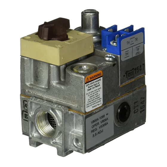
IF YOU HAVE ADDITIONAL QUESTIONS, NEED FURTHER INFORMATION, OR WOULD LIKE TO COMMENT ON OUR PRODUCTS OR SERVICES, PLEASE WRITE OR PHONE: YOUR LOCAL HONEYWELL RESIDENTIAL DIVISION SALES OFFICE (CHECK WHITE PAGES OR PHONE DIRECTORY). RESIDENTIAL DIVISION CUSTOMER SERVICE HONEYWELL INC., 1885 DOUGLAS DRIVE NORTH... - Page 3 TABLE l—MODEL SPECIFICATIONS. MODEL STANDARD AMBlENT PRESSURE PRESSURE TYPE FACTORY SUFFIX TEMPERATURE REGULATOR REGULATOR RANGE TYPE MODEL 32° F to 175° F Standard V5306 [0” c to 79° c] 11.0 32° F to 175° F V5307 Nat. [0” c to 79° c] opening step full rate...
- Page 4 PRESSURE TAPPING: Taps are 1/8 in, NPT with plug knob. containing recess for 3/1 6 in. Allen wrench. Outlet tap DIMENSIONS: Refer to Figs. 1 and 2. standard, inlet tap available; specify when ordering. APPROVALS: PRESSURE RATING: A.G.A. rating 1/2 psi [3.5 kPa] inlet AMERICAN GAS ASSOCIATION DESIGN CERTIFl- pressure.
- Page 5 high capacity 1 in. BSPP by 1 in. BSPP gas control. 1. Inlet pressure tap, 1/8 in. NPT. THERMOCOUPLE REQUIRED (ordered separately) for 2. Side outlets. 24V, 100V, 120V, and 2201240V models: Q309 orQ340 suggested. REPLACEMENT PARTS: Nominal output: 30 mV, 0.02 ohms, 1.392451-1 Energy Cutoff (ECO) Connector.
- Page 6 INSTALL PIPING TO CONTROL 4. Apply a moderate amount of good quality pipe com- pound (DO NOT use Teflon tape) to pipe only, leaving All piping must comply with local codes and ordi- two end threads bare. On LP installations, use compound nances or with National Fuel Gas Code (ANSI Z223.1 resistant to LP gas.
- Page 7 5. Connect other end of tubing to pilot burner accord- NOTE: When replacing a control, cut off old compression ing to pilot burner manufacturer’s instructions. fitting and replace with new compression fitting pro- vided on new combination gas control. Never use old compression fitting as it mav not cwovide a aas-tiaht CONNECT THERMOCOUPLE (24V, 10OV, 120V, and The thermocouple connection to the power unit or...
- Page 8 WIRING Follow wiring instructions furnished by appliance manu- LINE VOLTAGE facturer, if available, or use general instructions provided OPERATOR below. Where instructions differ, follow appliance OR CONTROLLER manufacturer’s instructions. All wiring must comply with applicable electrical codes and ordinances or with the National Electrical Code (ANS1/ (HOT) JUNCTION BOX- LIMIT...
- Page 9 POWERPILE GENERATOR FIG. 12—TYPICAL WIRING CONNECTIONS FOR GAS CONTROL WITH FOUR-TERMINAL OPERATOR. injury caused from hidden leaks which could cause flash- back in the appliance vestibule. Light main burner. 4. With main burner in operation, paint pipe joints (in- cluding adapters) and control inlet and outlet with rich soap and water solution.
- Page 10 TURN ON MAIN BURNER a. Remove pressure regulator adjustment cap and screw. Follow instructions provided by appliance manufac- turer or turn up thermostat to call for heat. b. Using screwdriver, turn inner adjustment screw c l o c k w i s e n t o i n c r e a s e o r counterclockwise n to decrease gas pressure CHECK AND ADJUST GAS INPUT TO MAIN BURNER c.
- Page 11 TABLE 9A—PRESSURE REGULATOR SPECIFICATION PRESSURES IN kPa. OUTLET PRESSURE NOMINAL RANGE FACTORY SETTING TYPE NOMINAL INLET STEP FULL RATE STEP FULL RATE OF GAS PRESSURE RANGE MODEL — — 0.7-1.2 1.2-1.7 — — 2.0-3.0 2.9-3.9 VS821A None 0.7-1.2 1.2-1.7 2.0-3.0 None 2.9-3.9 CHECK SAFETY SHUTDOWN PERFORMANCE...
- Page 12 ation channel to the gas outlet to the main burner. The The V800 combination gas control family provides 3- safety valve remains open, allowing pilot gas flow. position (OFF-PILOT-ON) manual control of gas flow. In Fig. 14, the gas control knob is in the ON position, the pilot is proven by the thermocouple/generator, and the thermostat is calling for heat.
- Page 13 GAS CONTROL SERVO PRESSURE REGULATOR INLET PRESSURE CHAMBER 12,882 DIAPHRAGM FIG. 14—GAS FLOW THROUGH THE V800 COMBINATION GAS CONTROL FAMILY. 60-201 9—7...
- Page 14 3. For VS820 and VS821, disconnect Ieadwiresto lower left TH terminal and lower right PP terminal to isolate valve operator coil from balance of circuit. Measure resistance of coil. If coil is not 2 ohms * 10 percent, replace VS824A FIRE OR EXPLOSION HAZARD Valve Operator.
- Page 15 7. Find the pilot—follow metal tube from gas control. The pilot is between the two burner tubes behind the pilot Follow the appliance manufacturer’s instructions. access panel. The information below will assist in typical control 8. Turn knob on gas control counterclockwise m t o applications, but the specific controls may require PILOT.