Table of Contents
Advertisement
Quick Links
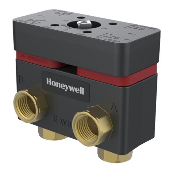
VB6 SERIES 6-WAY CONTROL BALL VALVES
AND ACTUATORS
Application
The VB6 6-Way Control Ball Valves regulates hot
and chilled water with glycol solutions up to 60%
in heating, ventilating, and air conditioning
(HVAC) systems.
These valves ship with a direct coupled actuator
factory installed for modulating control. The valve
is
designed
to
be used
MN7510A2001 actuator.
Application Notes
IMPORTANT:
Valve sizing is important for correct system
operation. Undersized valves do not have suf-
ficient capacity at maximum load. Oversized
valves do not have sufficient authority over
the load in modulating applications.
Oversized valves can cause excessive cycling
and the seat and ball can be damaged because
of the restricted opening.
Proper Use
These valves are intended for use in chilled water
and hot water closed loop applications only, with
a media temperature range of 0 ºF to +212 ºF (18
ºC to 100 ºC), and static pressures up to 600 psi.
® U.S. Registered Trademark
Copyright © 2021 Honeywell Inc. • All Rights Reserved
exclusively
with
Printed in USA
INSTALLATION INSTRUCTIONS
These valves are to be operated with the Honey-
well MN7510A2001 actuator only.
Water should be properly filtered, treated and
conditioned for good operating performance,
according to local conditions, and recommenda-
tions of the boiler or chiller manufacturers. The
installation of strainers and filters is recom-
mended.
IMPORTANT:
The presence of excessive iron oxide (red rust)
in the system voids the valve warranty.
Required Operating Torque
The VB6 series 6-way control ball valves are to be
operated with the Honeywell MN7510A2001
actuator only
These valves use a patented seat design that
reduces the torque needed. The nominal required
operating torque is 88 lb-in.
Table 1. Close off Pressure
Valve Size
1/2 inch and 3/4 inch
Flow Characteristic
The VB6 series 6-way Ball Valves have true equal
percentage flow characteristic, thanks to preci-
sion machined metal discs in front of the ball.
31-00380M-02
Close off Pressure
200 psi (1380 kPa)
31-00380M-02
Advertisement
Table of Contents

Related Manuals for Honeywell VB6 Series


Summary of Contents for Honeywell VB6 Series
- Page 1 The presence of excessive iron oxide (red rust) in the system voids the valve warranty. Required Operating Torque Application The VB6 series 6-way control ball valves are to be operated with the Honeywell MN7510A2001 The VB6 6-Way Control Ball Valves regulates hot actuator only...
-
Page 2: Valve Sizing
VB6 SERIES 6-WAY CONTROL BALL VALVES AND ACTUATORS - INSTALLATION INSTRUCTIONS Valve Sizing Typical pressure drop across a control valve is in the range of 3 to 5 psid, however the best control is achieved when the valve pressure drop is as close to the coil pressure drop as possible. - Page 3 VB6 SERIES 6-WAY CONTROL BALL VALVES AND ACTUATORS - INSTALLATION INSTRUCTIONS Mechanical Installation of the use 4-6 rounds of tape applied tightly in clockwise rotation. When using hemp as pipe Valve sealant, ensure no strands are left in the valve or piping.
-
Page 4: Mounting Position
VB6 SERIES 6-WAY CONTROL BALL VALVES AND ACTUATORS - INSTALLATION INSTRUCTIONS Mechanical Installation for Actuator Caution: To avoid personal injury (electrical shock) and to prevent equipment damage, before installation, you must remove power. Mounting Position 1. Choose a mounting position permitting easy access to cables and controls. - Page 5 VB6 SERIES 6-WAY CONTROL BALL VALVES AND ACTUATORS - INSTALLATION INSTRUCTIONS 3. Insert the Stem adapter into the Actuator output hub (Stem adapter and Output hub are keyed so they can be assembled in one way only). Figure 8. Assembly of Brass sleeve 6.
- Page 6 VB6 SERIES 6-WAY CONTROL BALL VALVES AND ACTUATORS - INSTALLATION INSTRUCTIONS Figure 10. Mounting of Screw in actuator assembly 8. Hold the handle in the vertical position (as shown below) and insert the handle on the linkage Stem adapter knob by pressing it downwards (press fit) to assemble it firmly.
-
Page 7: Electrical Installation
VB6 SERIES 6-WAY CONTROL BALL VALVES AND ACTUATORS - INSTALLATION INSTRUCTIONS Electrical Installation The most important part of the electrical installa- tion is the power supply for the actuator. Caution: To avoid personal injury (electrical shock) and to prevent equipment damage, before installation, you must remove power. -
Page 8: Modulating Run Mode
VB6 SERIES 6-WAY CONTROL BALL VALVES AND ACTUATORS - INSTALLATION INSTRUCTIONS Modulating Run Mode The Modulating Run mode can be used in four different types of control settings: • 2…10 Vdc • 0…10 Vdc • 10…0 Vdc • 10…2 Vdc... -
Page 9: Power-Off Behavior
VB6 SERIES 6-WAY CONTROL BALL VALVES AND ACTUATORS - INSTALLATION INSTRUCTIONS Power-Off Behavior IMPORTANT: The zero (closed) position of the valve can be If power is removed, the shaft adapter remains in achieved with control signal as shown in the position. - Page 10 VB6 SERIES 6-WAY CONTROL BALL VALVES AND ACTUATORS - INSTALLATION INSTRUCTIONS Flow Rate as per Valve Pressure Difference (ΔP) Table 3. Flow rate as per Valve Pressure difference Δ Valve CV Value Flow Rate (in gpm) for below Valve P (in psid)
- Page 11 VB6 SERIES 6-WAY CONTROL BALL VALVES AND ACTUATORS - INSTALLATION INSTRUCTIONS DIMENSIONS Dimension of Valve body Figure 18. Dimension of VB6 series 6-way control valve Table 2. Dimensions Valve nominal size Valve Body Inch inch (mm) inch (mm) inch (mm)
- Page 12 The material in this document is for information purposes only. The content and the product described are subject to change without notice. Honeywell makes no representations or warranties with respect to this document. In no event shall Honeywell be liable for technical or editorial omissions or mistakes in this document, nor shall it be liable for any damages, direct or incidental, arising out of or related to the use of this document.