Cisco Catalyst IR1800 Rugged Series Installation Manual
Hide thumbs
Also See for Catalyst IR1800 Rugged Series:
- Hardware installation manual (112 pages) ,
- Installation manual (96 pages) ,
- Connecting (4 pages)
Table of Contents
Advertisement
Quick Links
Advertisement
Chapters
Table of Contents

Related Manuals for Cisco Catalyst IR1800 Rugged Series


Summary of Contents for Cisco Catalyst IR1800 Rugged Series
- Page 1 Cisco Catalyst IR1800 Rugged Series Router Hardware Installation Guide First Published: 2021-02-03 Last Modified: 2021-07-02 Americas Headquarters Cisco Systems, Inc. 170 West Tasman Drive San Jose, CA 95134-1706 http://www.cisco.com Tel: 408 526-4000 800 553-NETS (6387) Fax: 408 527-0883...
- Page 2 © 2021 Cisco Systems, Inc. All rights reserved.
- Page 3 • Connect the equipment into an outlet on a circuit different from that to which the receiver is connected. • Consult the dealer or an experienced radio/TV technician for help. Modifications to this product not authorized by Cisco could void the FCC approval and negate your authority to operate the product.
- Page 4 Cisco has more than 200 offices worldwide. Addresses and phone numbers are listed on the Cisco website at www.cisco.com/go/offices. Cisco and the Cisco logo are trademarks or registered trademarks of Cisco and/or its affiliates in the U.S. and other countries. To view a list of Cisco trademarks, go to this URL: https://www.cisco.com/c/en/us/about/...
-
Page 5: Table Of Contents
RFP documentation, or language that is used by a referenced third-party product. The sections are: Objective This guide provides an overview and explains how to install and connect your Cisco device. Audience This guide is intended for people who have a high level of technical ability, although they may not have experience with Cisco software. -
Page 6: Conventions
Use the statement number provided at the end of each warning to locate its translation in the translated safety warnings that accompanied this device. Statement 1071 Cisco Catalyst IR1800 Rugged Series Router Hardware Installation Guide... - Page 7 à la fin de chaque avertissement. CONSERVEZ CES INFORMATIONS Cisco Catalyst IR1800 Rugged Series Router Hardware Installation Guide...
- Page 8 Utilize o número da instrução fornecido ao final de cada aviso para localizar sua tradução nos avisos de segurança traduzidos que acompanham este dispositivo. GUARDE ESTAS INSTRUÇÕES Cisco Catalyst IR1800 Rugged Series Router Hardware Installation Guide...
- Page 9 Använd det nummer som finns i slutet av varje varning för att hitta dess översättning i de översatta säkerhetsvarningar som medföljer denna anordning. SPARA DESSA ANVISNINGAR Cisco Catalyst IR1800 Rugged Series Router Hardware Installation Guide...
- Page 10 Brug erklæringsnummeret efter hver advarsel for at finde oversættelsen i de oversatte advarsler, der fulgte med denne enhed. GEM DISSE ANVISNINGER Cisco Catalyst IR1800 Rugged Series Router Hardware Installation Guide...
- Page 11 Law prohibits the use of UL-certified cables (that have the “UL” shown on the code) for any other electrical devices than products designated by CISCO. The use of cables that are certified by Electrical Appliance and Material Safety Law (that have “PSE” shown on the code) is not limited to CISCO-designated products.
- Page 12 1040 Warning The covers are an integral part of the safety design of the product. Do not operate the unit without the covers installed. Statement 1077 Warning Hot surface. Statement 1079 Cisco Catalyst IR1800 Rugged Series Router Hardware Installation Guide...
-
Page 13: Related Documentation
Full Reader Search window to search multiple PDF files simultaneously and to change case sensitivity and other options. Adobe Reader’s online help has more information about how to search PDF documents. Cisco Catalyst IR1800 Rugged Series Router Hardware Installation Guide... - Page 14 Preface Searching Cisco Documents Cisco Catalyst IR1800 Rugged Series Router Hardware Installation Guide...
-
Page 15: Overview
Router. For the purposes of this guide, it will be referred to as the IR1800 Series. General Description The Cisco Catalyst IR1800 Rugged Series Router is a next generation modular industrial router based on IOS XE, with advanced features such modular Wi-Fi, modular Cellular/WAN, CAN Bus, SSD, Digital I/O, GPS or GNSS Dead Reckoning. -
Page 16: Product Overview
(1) RS232 (1) RS232 (1) RS232 (1) RS232 DTE Interface (1) RS232 DCE/RS485 (1) RS232 (1) RS232 Cisco IR1800 Series Platform Features This section describes the different components of the router. Cisco Catalyst IR1800 Rugged Series Router Hardware Installation Guide... - Page 17 Product Overview Cisco IR1821 Router Cisco IR1821 Router Figure 1: Cisco IR1821 Router Cisco Catalyst IR1800 Rugged Series Router Hardware Installation Guide...
- Page 18 Product Overview Cisco IR1831 Router Cisco IR1831 Router Figure 2: Cisco IR1831 Router Cisco Catalyst IR1800 Rugged Series Router Hardware Installation Guide...
-
Page 19: Front Panel Overview
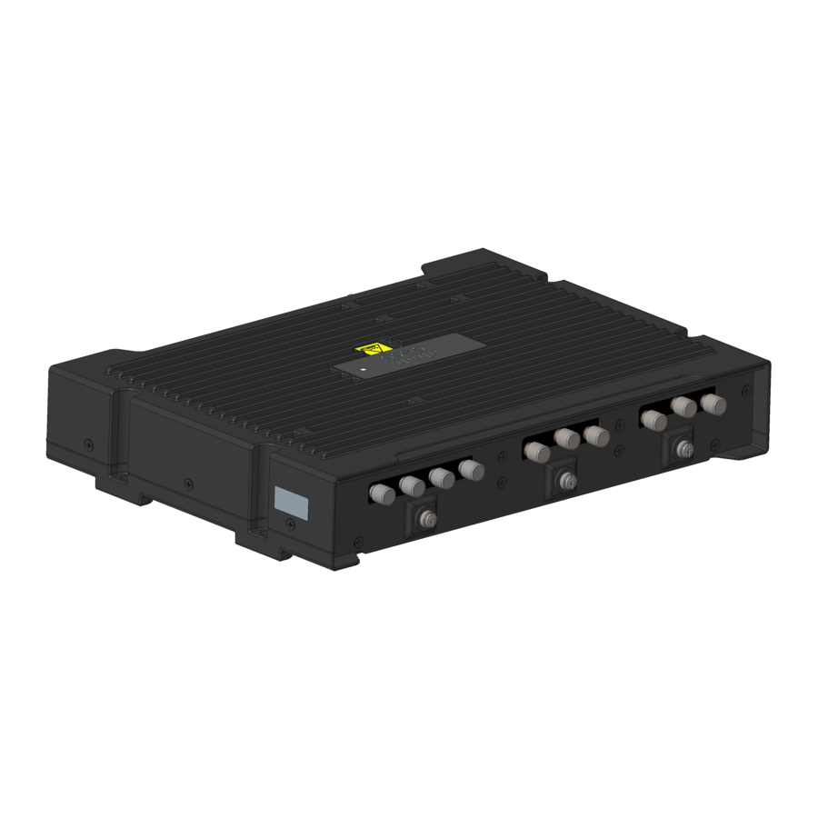
Product Overview Cisco IR1833 Router Cisco IR1833 Router Figure 3: Cisco IR1833 Router Cisco IR1835 Router Figure 4: Cisco IR1835 Router Front Panel Overview The IR1835 is seen below: Cisco Catalyst IR1800 Rugged Series Router Hardware Installation Guide... -
Page 20: Rear Panel Overview
Gigabit Ethernet LAN ports 0/1/2-0/1/3 Gigabit Ethernet 0/0/0 WAN Combo Ports (RJ-45 or SFP) Rear Panel Overview The IR1835 is seen below: Item Description Wi-Fi Interface Module (WIM) 0/3/0 Pluggable Interface Module 0/4/0 (PIM) Cisco Catalyst IR1800 Rugged Series Router Hardware Installation Guide... -
Page 21: Pluggable Interface Module (Pim)
Local connectors (LCs) provide the fiber-optic connection. RJ-45 connectors allow copper connections. You can use any combination of the supported SFP modules listed in the table that follows. Cisco Catalyst IR1800 Rugged Series Router Hardware Installation Guide... -
Page 22: Gigabit Ethernet Copper Ports
2 km GLC-FE-100LX-RGD 10 km For the most up-to-date list of supported SFP models for Cisco Industrial Ethernet switches, see the following:https://tmgmatrix.cisco.com/ Gigabit Ethernet Copper Ports The IR1800 has 4 RJ-45 copper ports. These copper ports support standard 3-speed, 10/100/1000Base-T Ethernet features including auto-MDIX, forced or auto-negotiation of speed and duplex, Fast Link Drop, and cable diagnostics. -
Page 23: Front Panel Leds
Steady Green - GNSS/DR configured, location fix achieved Flashing Green - GNSS/DR Active, trying to achieve location fix Off - GNSS/DR not configured SSD Module Steady Green - SSD being accessed Off - No power or not enabled Cisco Catalyst IR1800 Rugged Series Router Hardware Installation Guide... -
Page 24: Reset Button
Antenna Selection and Installation, page -23 chapter lists the supported Antennas and Accessories for the Cisco IR1800 with a wireless Pluggable Module. For detailed information about Cisco Antennas for the Industrial Routers, please refer to the following guide: Cisco Industrial Routers and Industrial Wireless Access Points Antenna Guide: http://www.cisco.com/c/en/us/td/docs/routers/connectedgrid/antennas/installing-combined/industrial-routers-and-industrial-wireless-antenna-guide.html... -
Page 25: Modem Support
Product Overview Modem Support Modem Support Software download for the pluggable modules supported in Cisco IR1800 can be found here: https://software.cisco.com/download/navigator.html?mdfid=286288566&flowid=76082 The following tables show the technology details for the modems. Table 6: Modem Technology Supported SKU ID Description Technology Supported P-LTE-VZ U.S. -
Page 26: Power Supply
1561.098 +/- 2.046 Power Supply The Cisco IR1800 comes with an external DC power connector. The 4-pin power entry connector (receptacle) is mounted to the unit. The 4-pin power entry mating connector (plug) is attached to the receptacle. It is removed during installation and used to connect to the DC power source, then reattached to provide power to the unit. -
Page 27: Usb Ports
• a connection (to the USB port) can only be made in a non-hazardous environment • the USB port cover must be reinstalled before the router can be deployed in a hazardous environment Cisco Catalyst IR1800 Rugged Series Router Hardware Installation Guide... - Page 28 Product Overview USB Ports Cisco Catalyst IR1800 Rugged Series Router Hardware Installation Guide...
-
Page 29: Overview
• Installing the Router Ground Connection, on page 37 Overview This section describes the equipment and the procedures for successfully installing the Cisco IR1800 ISR. Safety Information Caution Do not install the router or power supplies next to a heat source of any kind, including heating vents. -
Page 30: Equipment, Tools, And Connections
No antenna is shipped with the IR1800 by default. Items Shipped with your Router Unpack the box and verify that all items listed on the invoice were shipped with the Cisco IR1800. The following items are shipped with your router: •... -
Page 31: Installing The Router
1/4 in. (6 to 7mm). Mounting on a Wall, Table, or Other Flat Surface The Cisco IR1800 can be mounted in a vertical or horizontal orientation. It can be mounted using screws into studs in the wall, or using anchor mounting for hollow walls. - Page 32 Figure 6: Mounting Hole Dimensions Note Mount the router in a proper wall structure to carry the weight of the device. Whenever possible, use a mounting location where the screws will go into wall studs. Cisco Catalyst IR1800 Rugged Series Router Hardware Installation Guide...
-
Page 33: Installing A Din Rail
Use proper wall anchor mounts. Installing a DIN Rail The DIN Rail kit is ordered separately, the Cisco part number is IR1800-DINRAIL . Note The DIN Rail brackets come assembled in the horizontal orientation If your installation requires the vertical orientation, you will need to disassemble the componants and reassemble them. - Page 34 Once the bracket is attached to the router, it can be mounted onto the DIN Rail. Attaching the Bracket onto the DIN Rail To attach the Cisco IR1800 with the bracket to a DIN rail, refer to the following graphic and follow these steps.
- Page 35 Release the plastic latches after the DIN rail is firmly within the clamps to secure it. The router is now installed in the DIN rail. Step 4 To remove the router from the DIN Rail, simply reverse the procedure. Cisco Catalyst IR1800 Rugged Series Router Hardware Installation Guide...
- Page 36 Vertical orientation, you will need to disassemble the bracket hardware and reassemble it in the new orientation. The Horizontal orientation is shown in the following graphic: Figure 8: Horizontal Orientation The Vertical orientation is shown in the following graphic: Cisco Catalyst IR1800 Rugged Series Router Hardware Installation Guide...
- Page 37 Installing the Router Bracket Disassembly Figure 9: Vertical Orientation Bracket Disassembly To disassemble the bracket hardware, refer to the following graphic and follow the steps. Cisco Catalyst IR1800 Rugged Series Router Hardware Installation Guide...
- Page 38 Remove the two DIN Rail clips (5) from the mounting bracket. Step 5 Retain all components for re-use when mounting with the vertical orientation. What to do next Move on to Bracket Reassembly. Cisco Catalyst IR1800 Rugged Series Router Hardware Installation Guide...
- Page 39 The following procedure reattaches all of the bracket componants to allow for vertical orientation. Refer to the following graphics and follow the steps. Procedure Step 1 Slide the two springs (3) onto the thin tabs. Cisco Catalyst IR1800 Rugged Series Router Hardware Installation Guide...
- Page 40 Mounting the DIN Rail Bracket on the Router (Vertical) Procedure Step 1 First, attach the DIN rail bracket to the back of the router. Refer to the following graphic for guidence. Cisco Catalyst IR1800 Rugged Series Router Hardware Installation Guide...
-
Page 41: Installing The Router Ground Connection
Caution Cable distribution system should be grounded (earthed) in accordance with ANSI/NFPA 70, the National Electrical Code (NEC), in particular Section 820.93, Grounding of Outer Conductive Shield of a Coaxial Cable. Cisco Catalyst IR1800 Rugged Series Router Hardware Installation Guide... - Page 42 What to do next After you install and properly ground the router, you can connect the power wiring, the LAN cables, and the cables for administrative access as required for your installation. Cisco Catalyst IR1800 Rugged Series Router Hardware Installation Guide...
- Page 43 Overview Note Before you install the Cisco IR1800 Integrated Services Router on a table, wall, or DIN rail, install the antennas on the Pluggable Module. It is difficult to install the antennas after the router is installed. The following section contains information for selecting antennas on the IR1800 router.
- Page 44 • Solid and precast concrete walls limit signal penetration to one or two walls without degradation of coverage. • Concrete and wood block walls limit signal penetration to three or four walls. • A signal can penetrate five or six walls constructed of drywall or wood. Cisco Catalyst IR1800 Rugged Series Router Hardware Installation Guide...
- Page 45 Antenna Selection Single Port PID LTE CAT4 P-LTE-GB 2 x LTE(4G) antennas P-LTE-NA LTE-ANTM2-SMA-D P-LTE-VZ P-LTE-IN P-LTE-AU P-LTE-MNA LTE CAT6 P-LTEA-LA 2 x LTE(4G) antennas P-LTEA-EA LTE-ANTM2-SMA-D P-LTEAP18-GL 4 x LTE(4G/5G) antennas CAT18 LTE-ANTM2-SMA-D Cisco Catalyst IR1800 Rugged Series Router Hardware Installation Guide...
- Page 46 Antenna Type: Dipole Frequency Band: 617-960 MHz 1400-1700 MHz 1710-2690 MHz 3400-3900 MHz 5150-6000 MHz Connector: SMA (m) Indoor W-ANTM2050D-RPSMA Antenna Type: Dipole Wi-Fi Frequency Band: 2400-2500 MHz 5150-5850MHz Connector: RP SMA Cisco Catalyst IR1800 Rugged Series Router Hardware Installation Guide...
- Page 47 Antenna Type: Multi-Element Antennas will require proper TNC to SMA Vehicle Mount/Fixed Connectors: 4G LTE (2x) adapters. Infrastructure TNC (m) Location services only GNSS SMA (F) supported in domains with GNSS coverage. Cisco Catalyst IR1800 Rugged Series Router Hardware Installation Guide...
- Page 48 Wi-Fi (4x) RP-SMA (m) Supported Antennas, Extension Bases, andCables fortheIR1800 Antenna Type Antenna PIDs Cable(s) PID Extension Base Indoor (cellular) LTE-ANTM2-SMA-D CAB-L240-10-SM-TM LTE-AE-MAG-SMA CAB-L240-15-SM-TM CAB-L240-20-SM-TM Indoor (Wi-Fi) W-ANTM2050D-RPSMA= Outdoor ANT-4G-OMNI-OUT-N CAB-L240-10-SM-NM (cellular) ANT-5G-OMNI-OUT-N Cisco Catalyst IR1800 Rugged Series Router Hardware Installation Guide...
- Page 49 • All Cellular interfaces are supported through a Pluggable Module • Micro-Sim, 3FF size. Cisco recommends Industrial Temp micro SIMs that are rated from -40C to +105C • To ensure a reliable contact to the SIM socket, gold plated SIM cards must be used The following graphics show examples of a Pluggable Module.
- Page 50 Pluggable Interface Modules Installation Figure 12: LTE Pluggable Module (with antennas) Installation The modular cellular modem Pluggable Module remove and replace options are shown. Cisco Catalyst IR1800 Rugged Series Router Hardware Installation Guide...
- Page 51 Prepare the cellular modem module by inserting the micro sims applicable for your modems into the device. Remove the screw (1) holding the access plate in place that covers the sim slots. It is located on the side of the module, as shown in the following graphics. Cisco Catalyst IR1800 Rugged Series Router Hardware Installation Guide...
- Page 52 Step 4 Install your sims as shown in the following graphic. Make note of the proper slot number and sim orientation. Figure 15: Sim Installation Item Description Micro SIMs SIM 0 Cisco Catalyst IR1800 Rugged Series Router Hardware Installation Guide...
- Page 53 Step 7 Tighten the latch lock screw to a torque of 2.8 to 3.8 inch-lbs (0.3 to 0.4 newton meter). Refer to the following graphic for a finished USB cover installation. Cisco Catalyst IR1800 Rugged Series Router Hardware Installation Guide...
- Page 54 Step 10 If no antennas are being installed on a port, make sure the caps are installed on the connector. Cisco Catalyst IR1800 Rugged Series Router Hardware Installation Guide...
- Page 55 • Provides an additional 100GB of additional flash memory storage • Main purpose is to provide space to store application data for IOx • Field Replaceable unit, but is not hot-swappable. Cisco Catalyst IR1800 Rugged Series Router Hardware Installation Guide...
- Page 56 Figure 20: SSD Module Cover Step 2 Insert the SSD module into the slot on the panel so the previously removed screws (1) align with the screw holes (2). Refer to the following figure. Cisco Catalyst IR1800 Rugged Series Router Hardware Installation Guide...
- Page 57 After the module is properly inserted, tighten the module plate to the panel with the two screws. The screws should be torqued to 2-3 in-lb (0.2-0.3 newton meter). Step 4 The installation is now complete. Cisco Catalyst IR1800 Rugged Series Router Hardware Installation Guide...
- Page 58 SSD Module Installing the SSD Module Cisco Catalyst IR1800 Rugged Series Router Hardware Installation Guide...
- Page 59 • Location - For geo-fencing and asset tracking. • GNSS data streaming to applications - Data stream, such as NMEA being sent to one or multiple destinations. The following figure shows the GNSS FRU Module: Cisco Catalyst IR1800 Rugged Series Router Hardware Installation Guide...
- Page 60 Step 1 Remove the protective cover over the GNSS slot by removing the 2 screws (1) using a Phillips driver. Retain these two screws for further use. Refer to the following figure. Cisco Catalyst IR1800 Rugged Series Router Hardware Installation Guide...
- Page 61 The installation is now complete. What to do next To remove the module, simply reverse the steps. 1. Power off the device. 2. Remove the screws. 3. Pull out the module. Cisco Catalyst IR1800 Rugged Series Router Hardware Installation Guide...
- Page 62 GNSS FRU Module Installation and Removal Cisco Catalyst IR1800 Rugged Series Router Hardware Installation Guide...
-
Page 63: Overview
• Reverse voltage protected and causes no damage to the equipment. • Digital input and output can coexist on different channel. • LED Indicator: provision-able, On: Active, Off: Non-active. • 4kV Surge protected (IEC 61000-4-5). Cisco Catalyst IR1800 Rugged Series Router Hardware Installation Guide... -
Page 64: The Digital I/O Connector
(following the battery voltage). Connect the Ignition Input (IGN) of the router to the ignition output of the automobile. The DC In + and DC In - leads can be directly connected to the battery, but it is recommended that they be connected after a fuse. Cisco Catalyst IR1800 Rugged Series Router Hardware Installation Guide... -
Page 65: Digital I/O Specifications
• CAN Bus enables the ECU (electronic control unit) in a vehicle to communicate with all other ECUs • Consists of two wires, CAN bus High and Low supporting data rate up to 1 Mbs Cisco Catalyst IR1800 Rugged Series Router Hardware Installation Guide... -
Page 66: Can Bus Power Connector
CAN_P CAN bus Differential Signal DC + DC Power Input (12V, 24V) CAN_N CAN bus Differential Signal On-Board Diagnostic (OBD-II) The following are some of the characteristics of On-Board Diagnostic (OBD-II) Cisco Catalyst IR1800 Rugged Series Router Hardware Installation Guide... - Page 67 The list of the cables is illustrated by the picture below. The box Vehicle Conn is the connector mated to the car/truck. The box Tool Conn is for attaching diagnostic tool. The MiniFit-Jr is the connector shown above that will connect to the IR1800. Cisco Catalyst IR1800 Rugged Series Router Hardware Installation Guide...
- Page 68 Digital I/O, Ignition, and CAN Bus Connectivity On-Board Diagnostic (OBD-II) Cisco Catalyst IR1800 Rugged Series Router Hardware Installation Guide...
- Page 69 If you connect or disconnect the console cable with power applied to the switch or any device on the network, an electrical arc can occur. This could cause an explosion in hazardous location installations. Be sure that power is removed or the area is nonhazardous before proceeding. Statement 1080 Cisco Catalyst IR1800 Rugged Series Router Hardware Installation Guide...
- Page 70 If your laptop or PC warns you that you do not have the proper drivers to communicate with the router, you can obtain them from your computers manufacturer, or go here: https://www.silabs.com/developers/usb-to-uart-bridge-vcp-drivers Cisco Catalyst IR1800 Rugged Series Router Hardware Installation Guide...
- Page 71 The IR1800 uses a DC power accessory kit, part number PWR-MF4-125W-AC. This needs to be ordered separately. The power entry receptacle is on the IR1800. The pin-outs are shown in the following graphic: Cisco Catalyst IR1800 Rugged Series Router Hardware Installation Guide...
- Page 72 (CAB-PWR-15-MF4). The following is a diagram of the cable: Verifying Connections To verify that all devices are properly connected to the router, first turn on all the connected devices, then check the LEDs. Cisco Catalyst IR1800 Rugged Series Router Hardware Installation Guide...
- Page 73 In addition, the router is NOT designed for and should not be placed outdoors. The intent of the IP54 shroud is to provide supplementary protection to the router against dust and occasional splashing water. Cisco cannot guarantee prolonged reliable operation of the router if these guidelines are violated.
- Page 74 The Front Cover is shipped disassembled since it must be assembled onto the IR1800. There are four parts: Figure 28: Front Cover Parts From Top to Bottom, they are: • Top Cover Plate Cisco Catalyst IR1800 Rugged Series Router Hardware Installation Guide...
- Page 75 Make sure all cables are removed and that the desired FRUs or blanks are installed before assembling the front IP54 cover. Step 2 Attach the mounting plate to the front of the chassis using four of the provided screws. See the following graphic: Cisco Catalyst IR1800 Rugged Series Router Hardware Installation Guide...
- Page 76 All cables should be wedged between the top and bottom foam pieces. Step 7 Attach the top cover plate to the top cover using four more of the provided screws. See the following graphic: Cisco Catalyst IR1800 Rugged Series Router Hardware Installation Guide...
- Page 77 If your pluggable module has a USB port cover attached, remove the cover. If the USB port cover Note is installed along with the IP54 Back Cover, it will interfere with the installation. Cisco Catalyst IR1800 Rugged Series Router Hardware Installation Guide...
- Page 78 Once the cover is in place, antennae can be attached to the pluggable modules as needed. Step 5 The final assembly appears as in the following graphic: What to do next The IP54 Kit is now properly assembled. Cisco Catalyst IR1800 Rugged Series Router Hardware Installation Guide...
- Page 79 Overview This appendix provides specifications for the IR1800. Complete specifications for the IR1800 can be found in the marketing data sheet. Router Specifications The following table lists the specifications of the Cisco IR1800. Description Design Specification Dimensions 11.00”W x 7.16” x 2.02”...
- Page 80 Storage Temperature and Altitude Temperature: -40 to +85 degrees C Altitude: up to 15,000 feet Input Voltage Nominal voltage: 12V/24V (+/-20%) Min/Max voltage: +9.6V to +36V DC input Typical Current 5.5A Typical/Maximum Power Consumption Cisco Catalyst IR1800 Rugged Series Router Hardware Installation Guide...
-
Page 81: Related Documentation
Other important and helpful links to Cisco information are here: • Cisco.com: www.cisco.com • Warranty Information: www.cisco-warrantyfinder.com • Cisco Information Packet, consisting of Cisco Limited Warranty, Disclaimer of Warranty, End User License Agreement, and United States Federal Communications Commission Notice: www.cisco.com/en/US/docs/general/warranty/English/SL3DEN.html • Cisco Marketplace: www.cisco.com/pcgi-bin/marketplace/welcome.pl •... -
Page 82: Installation Warning And Caution Statements
(19.6 x 27.9 x 4.39 cm). To prevent the Router from overheating, there must be a minimum of 1.0 in. (25.4 mm) around all surfaces of the Router.Contact your Cisco Technical Assistance Centre (TAC) if tighter spacings are required. -
Page 83: Hazardous Locations Standards And Marking Strings
Information. Class A Notice for FCC Modifying the equipment without Cisco’s authorization may result in the equipment no longer complying with FCC requirements for Class A digital devices. In that event, your right to use the equipment may be limited by FCC regulations, and you may be required to correct any interference to radio or television communications at your own expense. -
Page 84: Industry Canada
® Cisco Catalyst IR1800 Rugged Series Router are certified to the requirements of RSS-247. The use of this device in a system operating either partially or completely outdoors may require the user to obtain a license for the system according to the Canadian regulations. For further information, contact your local Industry Canada office. -
Page 85: European Community, Switzerland, Norway, Iceland, And Liechtenstein
This equipment is intended to be used in all EU and EFTA countries. Outdoor use may be restricted to certain frequencies and/or may require a license for operation. For more details, contact Cisco Corporate Compliance. The product carries the CE Mark:... -
Page 86: Declaration Of Conformity For Rf Exposure
This section contains information on compliance with guidelines related to RF exposure. Generic Discussion on RF Exposure The Cisco products are designed to comply with the following national and international standards on Human Exposure to Radio Frequencies: • US 47 Code of Federal Regulations Part 2 Subpart J •... - Page 87 The IR1800 series includes a radio transmitter and receiver. It is designed not to exceed the limits for exposure to radio waves (radio frequency electromagnetic fields) as referenced in Health Canada Safety Code 6. The Cisco Catalyst IR1800 Rugged Series Router Hardware Installation Guide...
- Page 88 You can obtain additional information from the following organizations: • World Health Organization Internal Commission on Non-Ionizing Radiation Protection at this URL: www.who.int/emf • United Kingdom, National Radiological Protection Board at this URL: www.nrpb.org.uk Cisco Catalyst IR1800 Rugged Series Router Hardware Installation Guide...
-
Page 89: Emc Class A Notices And Warnings
This declaration is only valid for configurations (combinations of software, firmware and hardware) provided and/or supported by Cisco Systems for use within the EU or countries that have implemented the EU Directives. The use of software or firmware not supported/provided by Cisco Systems may result that the equipment is no longer compliant with the regulatory requirements. - Page 90 Tämä laite täyttää direktiivin 2014/53/EU olennaiset vaatimukset ja on siinä asetettujen muiden laitetta koskevien määräysten mukainen. Svenska [Swedish]: Denna utrustning är i överensstämmelse med de väsentliga kraven och andra relevanta bestämmelser i Direktiv 2014/53/EU. Cisco Catalyst IR1800 Rugged Series Router Hardware Installation Guide...
-
Page 91: National Restrictions
The outdoor usage of the 2.4 GHz band requires an authorization from the Electronic Communications Office. Please check http://www.esd.lv for more details. 2,4 GHz frekvenču joslas izmantošanai ārpus telpām nepieciešama atļauja no Elektronisko sakaru direkcijas. Vairāk informācijas: http://www.esd.lv Cisco Catalyst IR1800 Rugged Series Router Hardware Installation Guide... -
Page 92: Intended Use Of The Equipment
If you still have questions regarding the compliance of these products or you can not find the information you are looking for, please send an email request to Cisco at complianceinfo@cisco.com. Cisco Catalyst IR1800 Rugged Series Router Hardware Installation Guide...