Table of Contents
Advertisement
Quick Links
[ 1 ] BASIC SPECIFICATIONS . . . . . . . . . . . . . . . . . . . . . . . . . . . . . . . . . . . . . . . . . . . .1
[ 2 ] EXTERNAL VIEW AND OPERATION PANEL FUNCTIONAL DESCRIPTIONS . .2
[ 3 ] UNPACKING AND . . . . . . . . . . . . . . . . . . . . . . . . . . . . . . . . . . . . . . . . . . . . . . . . . .5
[ 4 ] SUPPLIES . . . . . . . . . . . . . . . . . . . . . . . . . . . . . . . . . . . . . . . . . . . . . . . . . . . . . . . . . 6
[ 5 ] INTERNAL STRUCTURE . . . . . . . . . . . . . . . . . . . . . . . . . . . . . . . . . . . . . . . . . . . . .7
[ 6 ] COPY PROCESS . . . . . . . . . . . . . . . . . . . . . . . . . . . . . . . . . . . . . . . . . . . . . . . . . . .9
[ 7 ] OPERATIONAL DESCRIPTIONS . . . . . . . . . . . . . . . . . . . . . . . . . . . . . . . . . . . . .12
[ 8 ] DISASSEMBLY, ASSEMBLY . . . . . . . . . . . . . . . . . . . . . . . . . . . . . . . . . . . . . . . . .16
[ 9 ] SIMULATION AND SELF DIAGNOSICS . . . . . . . . . . . . . . . . . . . . . . . . . . . . . . . .22
[10] ADJUSTMENTS . . . . . . . . . . . . . . . . . . . . . . . . . . . . . . . . . . . . . . . . . . . . . . . . . . .27
[11] DRUM CARTRIDGE REPLACEMENT . . . . . . . . . . . . . . . . . . . . . . . . . . . . . . . . . .30
[12] CIRCUIT DIAGRAM . . . . . . . . . . . . . . . . . . . . . . . . . . . . . . . . . . . . . . . . . . . . . . . .32
Parts marked with "!" is important for maintaining the safety of the set. Be sure to replace these parts with specified
ones for maintaining the safety and performance of the set.
SERVICE MANUAL
CONTENTS
SHARP CORPORATION
CODE: 00ZZ26SM1E///
MODEL
Z-21
MODEL
Z-26
MODEL
This document has been published to be used for
after sales service only.
The contents are subject to change without notice.
Advertisement
Table of Contents

Related Manuals for Sharp Z-21


Summary of Contents for Sharp Z-21
-
Page 1: Table Of Contents
SERVICE MANUAL CODE: 00ZZ26SM1E/// MODEL Z-21 MODEL Z-26 MODEL CONTENTS [ 1 ] BASIC SPECIFICATIONS ..........1 [ 2 ] EXTERNAL VIEW AND OPERATION PANEL FUNCTIONAL DESCRIPTIONS . - Page 2 7. Main PWB disassembly ......17 22. ACTUAL WIRING CHART-1: FOR Z-21 ... 51 8.
-
Page 3: 1 ] Basic Specifications
(50/60Hz common) Power consumption: Max. 690W (10WH or less in auto power shut off) External dimensions: Z-26, 378(W) x 353(D) x 98(H)mm; Z-21, 362(W) x 353(D) x 98(H)mm; Installation space: Z-26, 725(W) x 353(D)mm; Z-21, 675(W) x 353(D)mm Weight: Z-26: 6.7kg... -
Page 4: 2 ] External View And Operation Panel Functional Descriptions
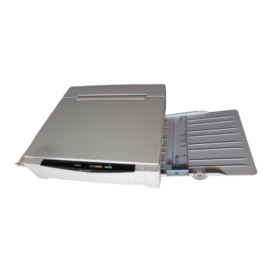
[2] EXTERNAL VIEW AND OPERATION PANEL FUNCTIONAL DESCRIPTIONS 1. Operation panel The illustrations show the Z-26. Rear side Release button (When moving the document table manually be sure to press and hold this button while moving. If the document table is moved without pressing this button, an necessary load is applied to the drive section, causing a Document cover... -
Page 5: Display Descriptions
Functions READY indicator Z-21: This indicator shows three states: ready, auto start, and auto power shut off mode. Ready state: When the power is turned on, this indicator lights up to show the machine is ready for copy operation, and for key input reception. - Page 6 EXPOSURE indicator Displays the value set by the EXPOSURE key. • In the case of Z-21, it is used also for counter read and when trouble occurs. • Toner save mode display lamp Displays the toner save mode selected by the copy density key.
-
Page 7: 3 ] Unpacking And
[3] INSTALLATION AND STORAGE 1. Unpacking Power cord 4. Although the copier can be stored standing up, place the copier Operation manual on a firm, level surface when using it. TD(Toner/Developer) cartridge Paper tray A small amount of ozone is produced within the copier during opera- tion. -
Page 8: 4 ] Supplies
3. Press the front-cover open button to unlatch the front cover and 9. Fit the paper tray in the copier by inserting it at an upward angle open it. into the grooves on the sides of the paper feed slot. (Z-26 only) Front-cover open button 10. -
Page 9: 5 ] Internal Structure
Power PWB document table sensor, and the paper entry sensor and the circuit which generates developing bias. Differs in the Z-21 and in the Z-26. Operation PWB Different from the conventional models, Copy lamp PWB the PWB is equipped with a fuse bulb. -
Page 10: Motors, Solenoids, Switches
2. Motors, solenoids, switches 3. Sensors, thermistor, thermostat Circuit Circuit Name diagram Type Function Name diagram Type Function code code Paper feed PID (Paper Senses paper Drive motor MM DC motor Drives all loads. Photo sensor sensor in detector) entry. Toner Toner supply is supply... -
Page 11: 6 ] Copy Process
[6] COPY PROCESS This model uses an OPC. (photoconductor) drum to form an image on it. 1. Copy process diagram Original SELFOC lens Copy lamp Main corona Exposure Charge Discharge Toner Developing Drum Developer Cleaning Cleaning blade Resist roller Waste toner collection Paper stoper Sync with Paper exit... - Page 12 Step 2. Charge Step 4. Developing A uniform negative charge is applied over the OPC drum surface by Toner is attracted from the MG roller to the latent image on the drum the main corona unit. (Controlled by the grid bias.) surface forming a visible image.
- Page 13 Step 6. Separation The paper is negatively charged (About –3KV) by the discharge pin to neutralize the potential, separating the paper from the drum. Step 7. Cleaning The residual toner remaining on the drum is collected by the cleaning blade and carried into the toner collection unit. Cleaning blabe Toner collection...
-
Page 14: 7 ] Operational Descriptions
In the Z-21, only single manual feed is available. 1-2. Void area and image loss The figure below shows the cross section of the Z-21 and the Z-26. Void area: With the original cover open, make a copy without an <Z-26>... -
Page 15: Outline Of Paper Feed Operation
C bracket unit Feed rack (Small pitch) <<Z-21>> When a paper is inserted into the paper feed port, the paper entry sensor turns on. The motor starts rotating to rotate the resist roller, transporting the paper to the paper stopper position. -
Page 16: Outline Of Operation
[When ready] In the auto shut off mode, if any key input is made or a paper is inserted (in the case of Z-21), the power relay is turned on to turn on the heater lamp (ready state). Power switch... -
Page 17: Toner Empty Control
5-2. Toner empty control When the paper entry sensor (Z-21) or the COPY key (Z-26) is turned on, if the toner control sensor output (TCS) is HIGH, the toner supply solenoid (THS) is turned on to supply toner. If TCS is not driven LOW after 60 sec of toner supply, the developer cartridge replacement lamp is lighted and the machine is stopped. -
Page 18: 8 ] Disassembly, Assembly
Remove the rack gear bracket. [8] DISASSEMBLY AND ASSEMBLY Note position of each component for reassembly. <<Note for disassembly and assembly>> (1) When disassembling, disconnect the power plug. Never remove or assemble the PWB or connectors with the power ON. (2) Be careful not to drop small parts and screws inside the machine. -
Page 19: Operation Panel Disassembly
4. Operation panel disassembly 6. AE sensor removal Remove the document table. Remove the document table. Remove the top cabinet. Remove the top cabinet. Remove the screw which is fixing the operation panel, and Remove the copy lamp unit (four screws). remove the connector. -
Page 20: Drive Unit Disassembly
Remove the MC cable (red) and GRID cable (white). (1 screw for 8. Drive unit disassembly each) Remove the document table. Spring Remove the top cabinet. White Remove the bottom cabinet. Note for attachment: Be careful not to mistake the attachment position of each cable. - Page 21 Motor encoder sensor PWB Motor encoder disk Disconnect the toner supply solenoid connector CN102, CN107, Remove the main chassis from the bottom base. (Z-21, 7 screws; CN111, and the heater lamp connector CN106. Z-26, 8 screws) Remove the grounding cable which is fixed to the drive unit with a screw.
-
Page 22: Drive Motor Disassembly
9. Drive motor disassembly 11. Lower heat roller disassembly Remove the document table. Remove the document table. Remove the top cabinet. Remove the top cabinet. Remove the bottom cabinet and remove the drum cartridge. Remove the bottom cabinet and the drum cartridge. Remove the motor encoder sensor PWB and the encoder. -
Page 23: Fusing Separation Pawl Disassembly
13. Fusing separation pawl disassembly Remove the two screws and an E-ring which are fixing the paper feed unit. Remove the document table and the top cabinet. Remove the fan unit and the main PWB. Remove the fusing separation pawls. 14. -
Page 24: 9 ] Simulation And Self Diagnosics
Auto exposure correction User Simulations 0 ∼ 3 cannot be executed in the Z-21. By installing the operation panel of the Z-26 to the Z-21, simulations 0 ∼ 3 can be executed in the Z-21. 1-1. Execution procedure Simulation No. and function... - Page 25 To terminate the simulation, release the short of the PWB, and turn off and then on the power. Drum counter clear Entering the simulation Total counter read (Z-21 only) Press and hold the EXPOSURE key and turn on the power. All the indicators except for the ready indicator light up.
- Page 26 Simulation No. and function Content <Display at total counter read> The display means as shown below: Value LED display READY indicator OFF= Digit of ten Blink Light thousands ON= Digit of thousands Blink= Digit of hundred Lead edge image loss adjustment Entering the simulation Copy lamp manual normal range Short the main PWB pins (JP210-JP211), turn on the power, and the misfeed indicator will...
- Page 27 Simulation No. and function Content <AE gain setting (manual)> With the exposure AUTO lamp blinking, turn the VR202 to set the AE (auto exposure) gain manually. When the VR202 is turned clockwise, brightness is increased. When the VR202 is turned counterclockwise, brightness is decreased. After completion of the setting, press the EXPOSURE key to establish and store the set value.
-
Page 28: Self Diag Functions
Since the Z-21 has no copy quantity display, the trouble codes are not displayed. When the display PWB of the Z-26 is connected to the Z-21, however, the trouble codes can be checked similarly with the Z-26. – 26 –... -
Page 29: Adjustments
• When the power unit is replaced. [10] ADJUSTMENTS Even in the other cases, when the drive section or the paper feed section is disassembled or when some parts in those sections are 1. Lead edge image loss adjustment replaced, check copy quality. Use a simulation to perform the lead edge adjustment. -
Page 30: Exposure Adjustment
<<Lead edge image loss adjustment procedure>> 2. Exposure adjustment Place a scale on the center of the document table and attach it The exposure adjustment is required in the following cases: with adhesive tape. • When replacing the drum unit. Turn off the power and remove the sensor cover in the paper exit •... - Page 31 • If the copy exposure is proper, the adjustment is completed. Turn off the power and remove the seal cover in the paper exit side. • If the copy exposure is not proper, go to step (4) again. Short the main PWB pins JP210 and JP211, and turn on the <<Standards>>...
-
Page 32: Drum Cartridge Replacement
7. Push the drum cartridge release lever up, rotate the cartridge [11] Drum cartridge replacement upwards and pull it out from the copier. The drum cartridge should be replaced by a service engineer, and should not be replaced by the user. 1. -
Page 33: Counter Clear
• The exposure indicators will light up for approximately 5 2-2. Counter clear seconds. Then, the READY indicator will light up and all the Turn the power switch on while pressing the EXPOSURE key at exposure indicators except (A) will go out. The copier is now the same time. -
Page 34: Circuit Diagram
[12] CIRCUIT DIAGRAM 1. BLOCK DIAGRAM Z-21 Operation panel VD (5V) DC Power supply PWB Main PWB AE sensor INLET CL (AC) Copy lamp control circuit RRS-A RRS-B High voltage circuit VH (31V) IC203 VD (5V) V18 (18V) VH (31V) -
Page 35: Main P.w.b Cpu (Ic203) Signal Name
2. NAIN PWB CPU (IC203) SIGNAL NAME PIN No. Port Signal name IN/OUT Active level Specifications P50/TXD SDA (EEPROM) OUT/IN — EEPROM data signal line P51/RXD — P52/SCK SCL (EEPROM) — EEPROM clock signal line /RES RESET Reset state at LOW (OV). /NMI /NM1 Driven LOW when the CPU is hung up,and interruption occurs. -
Page 36: Ac Power Supply Circuit: 100V Series
– 34 –... -
Page 37: Ac Power Supply Circuit: 200V Series
– 35 –... -
Page 38: Power Supply P.w.b. Circuit - 1/2 (Common Section)
– 36 –... -
Page 39: Power Supply P.w.b. Circuit - 2/2 (For Power Unit Cpwbf1018Fc51 Only)
– 37 –... -
Page 40: Bias Circuit/P.w.b
– 38 –... -
Page 41: Power Supply Circuit - 2/2 (For Power Unit Cpwbf1018Fc55, 56 Only)
– 39 –... -
Page 42: Power Supply P.w.b.: 100V Series
– 40 –... -
Page 43: Power Supply P.w.b.: 200V Series (Ex. 3Pin Plug): For Power Unit Cpwbf1043Fc** Only
– 41 –... -
Page 44: Main Control Circuit - 1/3 (Cpu Control Section)
– 42 –... -
Page 45: Main Control Circuit - 2/3 (I/O, Copy Lamp Control Section)
– 43 –... -
Page 46: Main Control Circuit - 3/3 (High Voltage Power Section)
– 44 –... -
Page 47: Main Control P.w.b
– 45 –... -
Page 48: Operation Circuit/P.w.b.-1: For Z-21
– 46 –... -
Page 49: Operation Circuit/P.w.b.-2: For Z-26
18. COPY LAMP CIRCUIT/PWB-1: 100V SERIES 100V F401 115˚C CLO2 CN401-1 CLO1 CN401-2 19. COPY LAMP CIRCUIT/PWB-2: 200V SERIES 200V F401 133˚C CLO1 CN401-1 CLO2 CN401-2 20. MES (Motor Encorder Sensor) CIRCUIT/P.W.B CN501-1 CN501-2 PD501 GP1S53V CN501-3 – 47 –... -
Page 50: Copy Lamp Circuit/P.w.b.-1: 100V Series
21. TIMING CHART (Z-21) Power switch Power relay 300msec 2.3sec 300msec Copy end, no key input After 90 sec Sleep mode ON with any key ⁄ " × 11" COPY • A4, 8 Power in SW Heater lamp DV bios Motor 2.0sec... -
Page 51: Timing Chart
– 49 –... - Page 52 – 50 –...
-
Page 53: Actual Wiring Chart-1: For Z-21
– 51 –... -
Page 54: Actual Wiring Chart-2: For Z-26
© COPYRIGHT 1997 BY SHARP CORPORATION All rights reserved. Printed in Japan. No part of this publication may be reproduced, stored in a retrieval system, or transmitted. In any form or by any means, electronic, mechanical, photocopying, recording, or otherwise, without prior written permission of the publisher.