Panasonic AK-HRP1005G Operating Manual
Hide thumbs
Also See for AK-HRP1005G:
- Operating instructions manual (141 pages) ,
- Operating manual (47 pages) ,
- Operation manual (37 pages)
Table of Contents
Advertisement
Quick Links
Operating Guide
Read this document when using the AK-HRP1005G Remote Operation Panel in
conjunction with AJ-PX5000G Memory Card Camera-Recorder.
For details of operating Remote Operation Panel AK-HRP1005G, please
visit the Panasonic website (https://pro-av.panasonic.net/manual/en/index.
html), and refer to the Operating Instruction (HTML or PDF).
W0918MN0 -PS
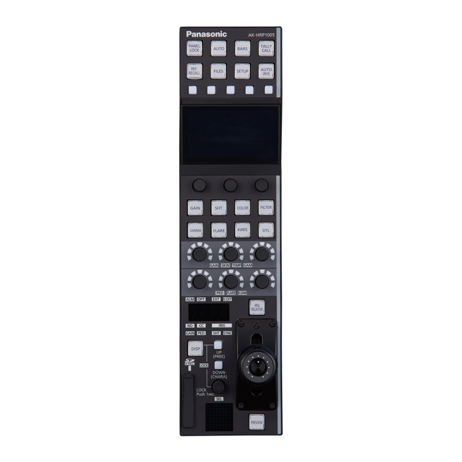
Remote Operation Panel
AK-HRP1005G
Model No.
ENGLISH
DVQP1926ZA
Advertisement
Table of Contents

Related Manuals for Panasonic AK-HRP1005G


Summary of Contents for Panasonic AK-HRP1005G
- Page 1 Operating Guide Remote Operation Panel AK-HRP1005G Model No. Read this document when using the AK-HRP1005G Remote Operation Panel in conjunction with AJ-PX5000G Memory Card Camera-Recorder. For details of operating Remote Operation Panel AK-HRP1005G, please visit the Panasonic website (https://pro-av.panasonic.net/manual/en/index.
-
Page 2: Table Of Contents
Table of Contents Connecting the Unit to AJ-PX5000G Cameras Connections Compatible Functions List ROP Menu (during AJ-PX5000G Connection) ROP menu list 01 PAINT SWITCH 02 SHUTTER SPEED 03 PEDESTAL 04 CHROMA 05 GAIN 06 WHITE BALANCE MODE 07 FLARE 08 GAMMA 09 BLACK GAMMA 10 KNEE 11 DRS... -
Page 3: Connecting The Unit To Aj-Px5000G Cameras
Connecting the Unit to AJ-PX5000G Cameras Connecting the Unit to AJ-PX5000G Cameras Connections Use a dedicated cable to connect the <REMOTE> connector at the rear of the AJ-PX5000G to the AK-HRP1005G’s <CCU> con- nector. Set the connection setting to “Serial(AJ)” in the [CONNECT SETTING] menu. -
Page 4: Compatible Functions List
Connecting the Unit to AJ-PX5000G Cameras Compatible Functions List When the unit is used in conjunction with an AJ-PX5000G Memory Card Camera-Recorder, a portion of the unit’s button, dial, and other control functions will be limited or disabled. Be sure to refer to the following table. Front panel 1 Front panel 2 Front panel 3... - Page 5 Connecting the Unit to AJ-PX5000G Cameras ✓ : Enabled Number Part name Remarks ×: Disabled ✓ [GAIN] button When this is set to ON, the [GAIN] menu appears on the LCD panel. ✓ [SHT] button When this is set to ON, the [SHUTTER SPEED] menu appears on the LCD panel.
- Page 6 Connecting the Unit to AJ-PX5000G Cameras ✓ : Enabled Number Part name Remarks ×: Disabled [ALM] indicator × [OPT] indicator × [EXT] indicator × [D.EXT] indicator × ✓ Adjustment value display ND filter/CC filter adjustment values are only dis- played. ✓...
-
Page 7: Rop Menu (During Aj-Px5000G Connection)
ROP Menu (during AJ-PX5000G Connection) ROP Menu (during AJ-PX5000G Connection) ROP menu list When an AJ-PX5000G Memory Card Camera-Recorder is connected, the ROP menu will be as follows. For details on menu operations, refer to the following sections in the Operating Instructions. “Displaying menus”... - Page 8 ROP Menu (during AJ-PX5000G Connection) “GAMMA R” (see page 19) GAMMA R GAMMA MASTER “GAMMA MASTER” (see page 19) GAMMA B “GAMMA B” (see page 19) GAMMA SEL “GAMMA SEL” (see page 19) “F-REC DYNMC(%)” (see page 19) F-REC DYNMC(%) 08 GAMMA “F-REC BLK STR(%)”...
- Page 9 ROP Menu (during AJ-PX5000G Connection) “TABLE” (see page 26) TABLE “R-G” (see page 26) “R-B” (see page 26) “G-R” (see page 26) 14 MATRIX “G-B” (see page 26) “B-R” (see page 26) “B-G” (see page 26) “MATRIX” (see page 26) MATRIX SAT R “SAT R”...
- Page 10 ROP Menu (during AJ-PX5000G Connection) IRIS LEV MODE Refer to the following section in the Operating Instructions. “37 ROP SETTING” M.PED CONT LOCK SELECT AUTO BUTTON G/M PED VOL FREE+LOCK CAM SEL DTL BUTTON SKIN VOL LCD BRIGHT PANEL BRIGHT B.GAMMA VOL BUZZER PERIOD...
- Page 11 ROP Menu (during AJ-PX5000G Connection) CAM1 to CAM99 IP ADDRESS Refer to the following section in the Operating Instructions. “40 CAMERA IP SETTING” 22 CAMERA IP SETTING CAM1 to CAM99 PORT CAM1 to CAM99 INF UPLOAD - 11 -...
-
Page 12: Paint Switch
ROP Menu (during AJ-PX5000G Connection) 01 PAINT SWITCH Item Setting details FLARE Enables or disables the flare. GAMMA Enables or disables the gamma. WHITE CLIP Enables or disables the white clip function. KNEE MANUAL Sets the mode used when the camera’s [OUTPUT / AUTO KNEE] selection switch is set to “OFF”. MATRIX Enables or disables matrix (linear matrix/12-axis color correction). -
Page 13: Shutter Speed
ROP Menu (during AJ-PX5000G Connection) 02 SHUTTER SPEED Item Setting details SHUTTER SPEED Sets the shutter speed for when [SHUTTER MODE] is set to “SHUT”. SHUTTER SYNCHRO Sets the shutter speed for when [SHUTTER MODE] is set to “SYNC”. Enables/disables the shutter function. MODE Selects the operation mode of the shutter. -
Page 14: Pedestal
ROP Menu (during AJ-PX5000G Connection) 03 PEDESTAL Item Setting details PED R Sets the correction level of red to the master pedestal. PED G Sets the correction level of green to the master pedestal. PED B Sets the correction level of blue to the master pedestal. - 14 -... -
Page 15: Chroma
ROP Menu (during AJ-PX5000G Connection) 04 CHROMA Item Setting details CHROMA LEVEL Sets the chroma level for the P and P signals. When this is set to “OFF”, the color components of the video signal are removed. - 15 -... -
Page 16: Gain
ROP Menu (during AJ-PX5000G Connection) 05 GAIN Item Setting details AWB A R Sets the Rch gain for when the [WHITE BAL] switch is set to the “A” position. AWB A B Sets the Bch gain for when the [WHITE BAL] switch is set to the “A” position. AWB B R Sets the Rch gain for when the [WHITE BAL] switch is set to the “B”... -
Page 17: White Balance Mode
ROP Menu (during AJ-PX5000G Connection) 06 WHITE BALANCE MODE Item Setting details COLOR TEMP PRE Sets the color temperature for when the [WHITE BAL] switch is set to the “PRST” position. AWB A TEMP Sets the color temperature for when “A” is selected with the [WHITE BAL] switch. AWB B TEMP Sets the color temperature for when “B”... -
Page 18: Flare
ROP Menu (during AJ-PX5000G Connection) 07 FLARE Item Setting details FLARE R Adjusts the Rch flare. FLARE G Adjusts the Gch flare. FLARE B Adjusts the Bch flare. FLARE Enables or disables flare correction. - 18 -... -
Page 19: Gamma
ROP Menu (during AJ-PX5000G Connection) 08 GAMMA Item Setting details GAMMA R Adjusts the red gamma characteristic for the master gamma. GAMMA MASTER Adjusts the gamma characteristic. GAMMA B Adjusts the blue gamma characteristic for the master gamma. GAMMA SEL Selects the gamma mode. - Page 20 ROP Menu (during AJ-PX5000G Connection) Item Setting details V-REC KNEE SLOPE(%) Sets the knee slope value for when [GAMMA SEL] is set to “VIDEO-REC”. This setting cannot be configured when “VIDEO-REC” is not selected. V-REC KNEE POINT(%) Sets the knee point value for when [GAMMA SEL] is set to “VIDEO-REC”. This setting cannot be configured when “VIDEO-REC”...
-
Page 21: Black Gamma
ROP Menu (during AJ-PX5000G Connection) 09 BLACK GAMMA Item Setting details BLACK GAMMA CURVE Sets the gamma curve for dark areas. BLACK GAMMA RANGE Sets the maximum level for compression/new creation. - 21 -... -
Page 22: Knee
ROP Menu (during AJ-PX5000G Connection) 10 KNEE Item Setting details MASTER POINT % Sets the knee point position. MASTER SLOPE Sets the knee slope. WHITE CLIP SW Enables or disables the white clip function. WHITE CLIP LEVEL Sets the white clip level. AUTO KNEE POINT % Sets the auto knee point position in 1% steps. -
Page 23: Drs
ROP Menu (during AJ-PX5000G Connection) 11 DRS Item Setting details MODE Sets the effectiveness of DRS color preservation. EFFECT DEPTH Sets the compression level for high-brightness areas of the dynamic range stretcher function. Higher values increase the compression level for high-brightness areas. - 23 -... -
Page 24: Hd Detail
ROP Menu (during AJ-PX5000G Connection) 12 HD DETAIL Item Setting details MASTER DETAIL Adjusts the level of master detail. DETAIL LV H Adjusts the level of horizontal detail. DETAIL LV V Adjusts the level of vertical detail. FREQ Selects the horizontal detail frequency. LEVEL DEPENDENT Sets the level to eliminate the detail in the dark areas. -
Page 25: Hd Skin Tone Dtl
ROP Menu (during AJ-PX5000G Connection) 13 HD SKIN TONE DTL Item Setting details SKIN DTL Selects the skin color table used when applying skin tone detail. The skin color table is created with [DETECT TBL]. When skin tone detail is applied, skin can be recorded to appear more smooth. -
Page 26: Matrix
ROP Menu (during AJ-PX5000G Connection) 14 MATRIX Item Setting details TABLE Selects the table for linear matrix. Adjusts the linear matrix between red and green. Not available when [MATRIX] is set to “OFF”. Adjusts the linear matrix between red and blue. Not available when [MATRIX] is set to “OFF”. -
Page 27: Color Correction
ROP Menu (during AJ-PX5000G Connection) 15 COLOR CORRECTION - 27 -... - Page 28 ROP Menu (during AJ-PX5000G Connection) Item Setting details SAT R Adjusts the color saturation of color components in the 12-axis matrix memory. When [COLOR CORRE] is set to “OFF”, the adjustment effects will not be applied. SAT R-MG SAT MG SAT MG-B SAT B SAT B-CY...
-
Page 29: Iris Relative
ROP Menu (during AJ-PX5000G Connection) 16 IRIS RELATIVE For details on operations and settings, refer to the following section in the Operating Instructions. “29 IRIS RELATIVE” - 29 -... -
Page 30: Hi-Color
ROP Menu (during AJ-PX5000G Connection) 17 HI-COLOR Item Setting details HI-COLOR SW Enables or disables the mode that expands dynamic range for colors. HI-COLOR LEVEL Selects the level for the mode that expands dynamic range for colors. - 30 -... -
Page 31: Camera Menu Control
ROP Menu (during AJ-PX5000G Connection) 18 CAMERA MENU CONTROL Item Setting details MENU ON/OFF Turns the menu on or off. CURSOR/PARAMETER Moves the menu cursor or changes setting values. EXECUTE Executes the selected process. NOTE Settings configured on the camera side will not be applied to the ROP while the menu on the camera is displayed. To apply the settings configured on the camera side, close the menu on the camera. -
Page 32: Rop Setting
ROP Menu (during AJ-PX5000G Connection) 19 ROP SETTING For details on operations and settings, refer to the following section in the Operating Instructions. “37 ROP SETTING” 20 CONNECT SETTING For details on operations and settings, refer to the following section in the Operating Instructions. “38 CONNECT SETTING”...