
Related Manuals for Cisco UCS B420 M3


Summary of Contents for Cisco UCS B420 M3
-
Page 1: Table Of Contents
Cisco UCS B420 M3 High Performance Blade Server Installation and Service Note Cisco UCS B420 M3 High Performance Blade Server LEDs Buttons Local Console Connector Drive Replacement Blade Server Removal and Installation Secure Digital Cards Removing a Blade Server Cover... -
Page 2: Cisco Ucs B420 M3 High Performance Blade Server
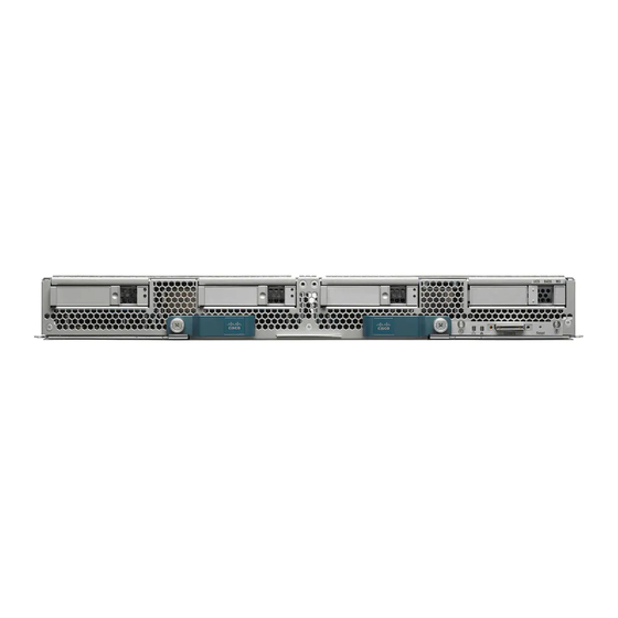
Cisco UCS B420 M3 High Performance Blade Server This document describes how to install and service the Cisco UCS B420 M3 High Performance Blade Server, a full-width blade server meaning up to four of these high-density, four-socket blade servers can reside in a Cisco UCS 5108 Blade Server chassis. -
Page 3: Leds
12 V main power and goes to standby power state. You cannot shut down standby power from the front-panel power button. See the Cisco UCS Manager Configuration Guide for information about completely powering off the server from the software interface. -
Page 4: Buttons
The power button allows you to manually take a server temporarily out of service but leave it in a state where it can be restarted quickly. If the desired power state for a service profile associated with a blade server is set to "off," using the power button or Cisco UCS Manager to reset the server will cause the desired power state of the server to become out of sync with the actual power state and the server may unexpectedly shut down at a later time. -
Page 5: Drive Replacement
URL:http://www.cisco.com/c/en/us/products/servers-unified-computing/ ucs-b-series-blade-servers/datasheet-listing.html Before upgrading or adding a drive to a running blade server, check the service profile in Cisco UCS Manager and make sure the new hardware configuration will be within the parameters allowed by the service profile. To prevent ESD damage, wear grounding wrist straps during these procedures. - Page 6 Procedure Step 1 Push the button to release the ejector, and then pull the hard drive from its slot. Step 2 Place the hard drive on an antistatic mat or antistatic foam if you are not immediately reinstalling it in another server. Step 3 Install a hard disk drive blank faceplate to keep dust out of the blade server if the slot will remain empty.
-
Page 7: Blade Server Removal And Installation
Push the hard drive lever into the closed position. You can use Cisco UCS Manager to format and configure RAID services. For details, see the Configuration Guide for the version of Cisco UCS Manager that you are using. The configuration guides are available at the following URL: http:// www.cisco.com/en/US/products/ps10281/products_installation_and_configuration_guides_list.html... - Page 8 Therefore, if a UCS B460 M4 blade server is present, it should be installed at the bottom, followed by full-width blades such as the UCS B420 M3 (and M4) above the UCS B460 M4, and then half-width blades such as the UCS B200 at the top of the chassis.
- Page 9 b) Pull the slot divider out of the chassis as shown in callout 2 of the following figure. Keep the slot divider in case it is needed at another time. Figure 4: Removing a Slot Divider To reinstall the slot divider, align it with the dimples in the slot top and bottom and slide it back in until it clicks into place.
-
Page 10: Secure Digital Cards
Step 2 Grasp the front of the blade server and place your other hand under the blade to support it. Figure 5: Positioning a Blade Server in the Chassis Step 3 Open the ejector levers in the front of the blade server. Step 4 Gently slide the blade into the blade slot opening until you cannot push it any farther. -
Page 11: Removing A Blade Server Cover
Note Due to technical limitations, if the server is running a Cisco UCS Manager version earlier than release 2.2(3a) with the 32-GB SD card, only 16-GB usable capacity is available (regardless of mirroring) in the server. Figure 6: SD Card Slots... - Page 12 Be sure that the tabs on the baffles are set in the slots provided on the motherboard; otherwise, it may be Caution difficult to replace the server cover or damage to the motherboard might occur. Figure 8: Cisco UCS B420 Air Baffles...
- Page 13 0.8 inches (20 mm), and no more than 1.345 inches (34 mm) long in order to provide needed clearances to install or remove the USB drive. Third-party USB flash memory is allowed but not subject to support by Cisco and is at the user’s risk. Diagnostics Button...
- Page 14 At blade start-up, POST diagnostics test the CPUs, DIMMs, HDDs, and adapter cards, and any failure notifications are sent to UCS Manager. You can view these notifications in the Cisco UCS Manager System Error Log or in the output of the show tech-support command.
-
Page 15: Working Inside The Blade Server
Installing a CMOS Battery All Cisco UCS blade servers use a CR2032 battery to preserve BIOS settings while the server is not installed in a powered-on chassis. Cisco supports the industry standard CR2032 battery that is available at most electronics stores. - Page 16 Step 2 Remove the heat sink. Remove the existing thermal compound from the bottom of the heat sink using the cleaning kit included with each CPU option kit. Follow the instructions on the two bottles of cleaning solvent. Step 3 Unhook the first socket hook, which has the following icon: See callout 3 in the following figure.
- Page 17 • A BIOS update is available and installed that supports the CPU and the given server configuration. • If the server will be managed by Cisco UCS Manager, the service profile for this server in Cisco UCS Manager will recognize and allow the new CPU.
- Page 18 Procedure Step 1 To install a CPU in an empty socket, remove the protective cap that is intended to prevent bent or touched contact pins. The pick and pull cap tool provided can be used in a manner similar to a pair of tweezers. Grasp the protective cap and pivot as shown.
- Page 19 e) Lift the tool and CPU straight up off of the pedestal. Figure 13: Loading the Pick and Place Tool Alignment mark on the pick and place tool, CPU and pedestal...
- Page 20 Step 4 Place the CPU and tool on the CPU socket with the registration marks aligned as shown. Step 5 Press the button/handle on the pick and place tool to release the CPU into the socket. Figure 14: Using the CPU Pick and Place Tool to Insert the CPU Alignment mark on the tool button/handle Alignment mark on the CPU socket...
- Page 21 Step 6 Close the socket latch. See callout 1 in the following figure. Step 7 Secure the first hook, which has the following icon: See callout 2 in the following figure. Step 8 Secure the second hook, which has the following icon: See callout 3 in the following figure.
- Page 22 Press the DIMM connector latches inward slightly to seat them fully. Supported DIMMs The DIMMs supported in this blade server are constantly being updated. A list of currently supported and available DIMMs is in the Cisco UCS B420 M3 specification sheet: http://www.cisco.com/c/dam/en/us/products/collateral/servers-unified-computing/ ucs-b-series-blade-servers/b420m3_specsheet.pdf.
- Page 23 Memory Arrangement The Cisco UCS B420 high-performance blade server contains 48 slots for installing DIMMs—12 for each CPU. Each CPU has 12 DIMM slots spread over 4 channels. This blade server needs at least one DIMM attached to all populated CPUs. DIMMs installed in slots for an absent CPU will not be recognized.
- Page 24 Table 2: UCS B420 M3 DIMM Slot Population DIMMs Populate CPU 1 Slots Populate CPU 2 Populate CPU 3 Populate CPU 4 Slots Color Coding per CPU Slots Slots Blue A0, B0 E0, F0 I0, J0 M0, N0 Blue A0, B0, C0...
- Page 25 Figure 18: Physical Representation of DIMMs and CPUs Figure 19: Logical Representation of Channels...
- Page 26 Memory Performance When configuring your server, consider the following: • DIMMs within the blade can be of different speeds, but all DIMMs will run at the speed of the DIMM with the lowest speed. • No mixing of DIMM type (LRDIMM, RDIMM, TSV-RDIMM) is allowed. •...
- Page 27 Installing a Virtual Interface Card Adapter You must remove the adapter card to service it. Note To install a Cisco VIC 1340 or VIC 1240 in the blade server, follow these steps: Procedure Step 1 Position the VIC board connector above the motherboard connector and align the captive screw to the standoff post on the motherboard.
- Page 28 Adapter cards can be installed in either slot 1 or slot 2; they can be of the same type or a mixed configuration. Cisco UCS Manager will recognize adapters in these slots as “Adapter 2” and “Adapter 3,” and counts the Note mLOM as being “Adapter 1.“...
- Page 29 Procedure Step 1 Position the adapter board connector above the motherboard connector and align the two adapter captive screws to the standoff posts (see callout 1) on the motherboard. Step 2 Firmly press the adapter connector into the motherboard connector (see callout 2). Step 3 Tighten the two captive screws (see callout 3).
- Page 30 Procedure Step 1 Using Cisco UCS Manager, perform a graceful shutdown of the server. Without a graceful shutdown, data can be permanently lost. Step 2 Remove the server from the chassis. Step 3 Remove the top cover from the server.
-
Page 31: Installing And Enabling A Trusted Platform Module
Installing and Enabling a Trusted Platform Module The Trusted Platform Module (TPM) is a component that can securely store artifacts used to authenticate the server. These artifacts can include passwords, certificates, or encryption keys. A TPM can also be used to store platform measurements that help ensure that the platform remains trustworthy. - Page 32 e) Continue with enabling TPM support in the server BIOS in the next step. Figure 23: TPM Socket Location Front of server TPM socket on motherboard Step 2 Enable TPM Support in the BIOS. a) Enable Quiet Mode in the BIOS policy of the server’s service profile. b) Establish a direct connection to the server, either by connecting a keyboard, monitor, and mouse to the front panel using a KVM dongle (N20-BKVM) or by other means.
-
Page 33: Server Troubleshooting
Cisco UCS blade servers should be configured and managed using Cisco UCS Manager. For details, see the Configuration Guide for the version of Cisco UCS Manager that you are using. The configuration guides are available at the following URL: http:// www.cisco.com/en/US/products/ps10281/products_installation_and_configuration_guides_list.html... - Page 34 Specification Value Depth 24.4 inches (620 mm) Weight 34.5 lbs (15.65 kg) The system weight listed here is an estimate for a fully configured system and will vary depending on peripheral devices installed.
-
Page 35: Related Cisco Ucs Documentation
Related Cisco UCS Documentation Documentation Roadmaps For a complete list of all B-Series documentation, see the Cisco UCS B-Series Servers Documentation Roadmap available at the following URL: http://www.cisco.com/go/unifiedcomputing/b-series-doc. For a complete list of all C-Series documentation, see the Cisco UCS C-Series Servers Documentation Roadmap available at the following URL: http://www.cisco.com/go/unifiedcomputing/c-series-doc. -
Page 36: Obtaining Documentation And Submitting A Service Request
Documentation, which also lists all new and revised Cisco technical documentation. Subscribe to the What's New in Cisco Product Documentation as a Really Simple Syndication (RSS) feed and set content to be delivered directly to your desktop using a reader application. The RSS feeds are a free service and Cisco currently supports RSS version 2.0. - Page 37 Cisco and the Cisco logo are trademarks or registered trademarks of Cisco and/or its affiliates in the U.S. and other countries. To view a list of Cisco trademarks, go to this URL: www.cisco.com/go/trademarks . Third-party trademarks mentioned are the property of their respective owners. The use of the word partner does not imply a partnership relationship between Cisco and any other company.
- Page 38 Cisco Systems, Inc. Cisco Systems (USA) Pte. Ltd. Cisco Systems International BV San Jose, CA 95134-1706 Singapore Amsterdam, The Netherlands Cisco has more than 200 offices worldwide. Addresses, phone numbers, and fax numbers are listed on the Cisco Website at www.cisco.com/go/offices.