Advertisement
Quick Links
For questions or help with this product contact Tech Support at (570) 546-9663 or techsupport@grizzly.com
Introduction
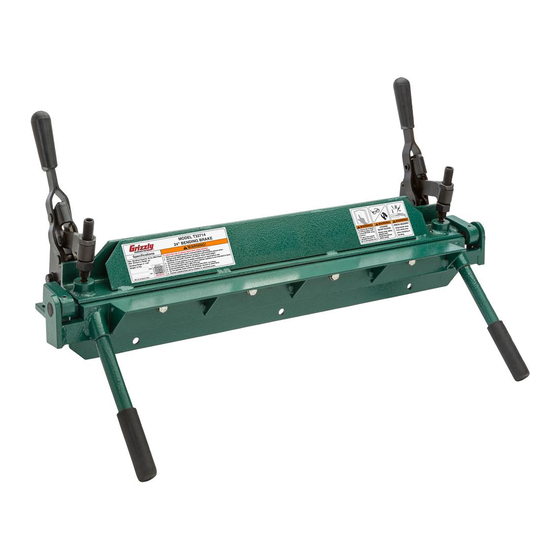
The Model T32714 24" Bending Brake is ideal for
a small workshop environment where the ease of
use is important. This machine can bend up to 20
gauge (0.0375 in. or 0.9525mm) mild steel.
To reduce your risk of
serious injury, read this
entire
using machine.
Figure 1. Model T32714 24" Bending Brake.
Specifications
•
Maximum Bending Angle ...................... 130°
•
Maximum Bending Capacity ........ 20 Gauge
•
Weight ................................................53 lbs.
OR FORM WITHOUT THE WRITTEN APPROVAL OF GRIZZLY INDUSTRIAL, INC.
manual
BEFORE
COPYRIGHT © MAY, 2021 BY GRIZZLY INDUSTRIAL, INC.
NO PORTION OF THIS MANUAL MAY BE REPRODUCED IN ANY SHAPE
(FOR MODELS MFD. SINCE 05/21) #CS21864 PRINTED IN CHINA
MODEL T32714
24" BENDING BRAKE
INSTRUCTIONS
Inventory
Description
A. Bending Brake ............................................ 1
B. Bending Levers .......................................... 2
C. Hex Wrenches 5, 8mm (Not Shown) ....1 Ea.
A
Figure 2. Inventory.
NOTICE
If you cannot find an item on this list, care-
fully check around/inside the machine and
packaging materials. Often, these items get
lost in packaging materials while unpack-
ing or they are pre-installed at the factory.
Needed for Setup
•
Safety Glasses ....................................1 Pair
•
Cleaner/Degreaser ..................... As Needed
•
Disposable Shop Rags ............... As Needed
•
Disposable Gloves ..................... As Needed
•
Open-End Wrenches
Qty
B
⁄
" ............................ 2
1
2
V1.05.21
Advertisement

Related Manuals for Grizzly T32714


Summary of Contents for Grizzly T32714
- Page 1 MODEL T32714 24" BENDING BRAKE INSTRUCTIONS For questions or help with this product contact Tech Support at (570) 546-9663 or techsupport@grizzly.com Introduction Inventory Description The Model T32714 24" Bending Brake is ideal for A. Bending Brake ..........1 a small workshop environment where the ease of B.
-
Page 2: Workbench Mounting
Flat Washer NOTICE Machine Base Avoid harsh solvents like acetone or brake parts cleaner that may damage painted sur- faces. Always test on a small, inconspicu- Workbench ous location first. Figure 4. "Direct Mount" setup. Model T32714 (Mfd. Since 05/21) - Page 3 = (a + b) – BD Side View Top View = Total workpiece length before bending a = Required finished height b = Required finished length BA = Bend allowance BD = Bend deduction Figure 6. Bend allowance measurements. Model T32714 (Mfd. Since 05/21)
-
Page 4: Adjusting Setback
— Loosen set screw to increase setback. Repeat Steps 1–2 until setback is equal on both sides of clamping leaf and correct for Breaker Bar operation. Figure 8. Location of clamping leaf and breaker bar. Model T32714 (Mfd. Since 05/21) - Page 5 Step 1 Figure 12. Example of workpiece clamped under clamping leaf. — If workpiece is too thick or thin to be securely clamped, refer to Adjusting Clamps on Page 6 to adjust them before proceeding. Model T32714 (Mfd. Since 05/21)
- Page 6 Open clamps and clamping leaf and remove workpiece. — Turn nuts clockwise for thinner workpiece. — Turn nuts counterclockwise for thicker workpiece. Repeat adjustment from Step 1 on second clamp, taking care to adjust both the same amount. Model T32714 (Mfd. Since 05/21)
- Page 7 Typical Bending Operation beginning on Page subsequent bends. 5 to radius bend. Note: The Model T32714 is only capable of bend- If you cannot get your bends close enough ing pans/boxes that have 90 degree angles. together for your operation, remove the fasteners shown in Figure 16 to remove the bending leaf from the breaker bar.
- Page 8 (see Figure 21). Figure 19. Clamping clearance for first bend. Crushing hazard! Always Figure 21. Typical workpiece ready for final keep hands clear when bend. using this machine. Model T32714 (Mfd. Since 05/21)
- Page 9 15. Open clamps and clamping leaf and remove workpiece. Figure 24. Location of pivot points. 16. Tap corner from Step 12 back into place (see Figure 23). Figure 23. Typical finished box. Model T32714 (Mfd. Since 05/21)
-
Page 10: Parts Breakdown & List
Please Note: We do our best to stock replacement parts whenever possible, but we cannot guarantee that all parts shown here are available for purchase. Call (800) 523-4777 or visit our online parts store at www.grizzly.com to check for availability. -
Page 11: Warranty And Returns
WARRANTY & RETURNS Grizzly Industrial, Inc. warrants every product it sells for a period of 1 year to the original purchaser from the date of purchase. This warranty does not apply to defects due directly or indirectly to misuse, abuse, negligence, accidents, repairs or alterations or lack of maintenance.