
Related Manuals for Omega FMA1700A


Summary of Contents for Omega FMA1700A
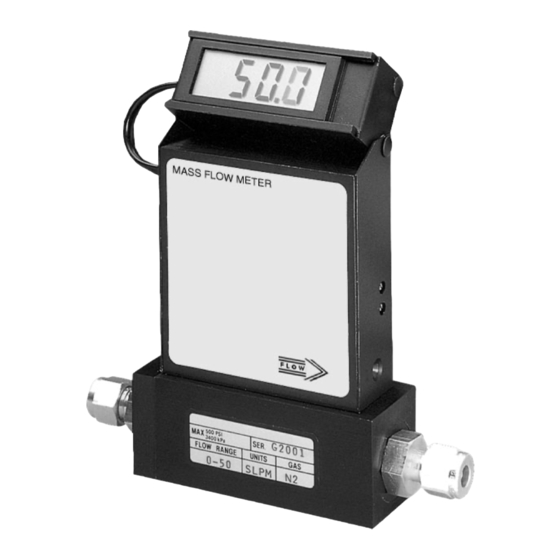
- Page 1 User’ s Guide Shop online at omega.com e-mail: info@omega.com For latest product manuals: www.omegamanual.info NORWALK, CT FMA1700A & FMA1800A Mass Flowmeter...
- Page 2 Fax: (203) 359-7700 e-mail: info@omega.com For Other Locations Visit omega.com/worldwide The information contained in this document is believed to be correct, but OMEGA accepts no liability for any errors it contains, and reserves the right to alter specifications without notice.
-
Page 3: Table Of Contents
TABLE OF CONTENTS 1. UNPACKING THE FMA1700A/1800A MASS FLOW METER..... Inspect Package for External Damage..........Unpack the Mass Flow Meter............... Returning Merchandise for Repair............2. INSTALLATION..................Primary Gas Connections..............Electrical Connections..............2.3.1 Remote LCD Readouts..............2.3.2 Panel Mounting Readouts..............3. PRINCIPLE OF OPERATION.............. - Page 4 7.3.6 50% Flow Adjustment..............7.3.7 75% Flow Adjustment..............7.3.8 100% Flow Adjustment..............LCD Display Scaling................. 7.4.1 Access LCD Display Circuit.............. 7.4.2 Adjust Scaling.................. 7.4.3 Change Decimal Point..............8. TROUBLESHOOTING................Common Conditions................ Troubleshooting Guide..............Technical Assistance............... 9. CALIBRATION CONVERSIONS FROM REFERENCE GASES....... APPENDIX 1 COMPONENT DIAGRAM............
-
Page 5: Unpacking The Fma1700A/1800A Mass Flow Meter
Unpack the Mass Flow Meter CAUTION: Some of the IC devices used in the FMA1700A & FMA1800A are Electro Static Discharge (ESD) sensitive and may be damaged by improper handling. When wiring interface connector, adjusting or servicing the meter, use of a grounded ESD protection wrist strap is required to prevent inadvertent damage to the CMOS integral solid state circuitry. -
Page 6: Electrical Connections
Restrictor Flow Elements (RFE's)! Using a Helium Leak Detector or other equivalent method perform a thorough leak test of the entire system. (All FMA1700A/1800A are checked prior to ship- ment for leakage within stated limits. See specifications in this manual.) Electrical Connections CAUTION: Some of the IC devices used in the FMA1700A &... - Page 7 The FMA1700A & FMA1800A flow meters have universal power input and can be used with any power supply voltage between +12 and +26 Vdc. CAUTION: BEFORE CONNECTING POWER SUPPLY CHECK YOUR METER SERIAL NUMBER AND POWER SUPPLY REQUREMENTS LABEL LOCATED ON THE FLOW METER BACK COVER.
-
Page 8: Remote Lcd Readouts
0-5 Vdc output and remote LCD display may not exceed 9.5 feet (3 meters). Use of the FMA1700A/1800A flow transducer in a manner other than that speci- fied in this manual or in writing from OMEGA7, may impair the protection provid- ed by the equipment. -
Page 9: Principle Of Operation
PRINCIPLE OF OPERATION The stream of gas entering the Mass Flow transducer is split by shunting a small portion of the flow through a capillary stainless steel sensor tube. The remainder of the gas flows through the primary flow conduit. The geometry of the primary con- duit and the sensor tube are designed to ensure laminar flow in each branch. -
Page 10: Specifications
RESPONSE TIME: 800 ms time constant; approximately 2 seconds to within ±2% of set flow rate for 25% to 100% of full scale flow rate. GAS PRESSURE: 1000 psig (69 bars) FMA1700A/1800A Series Max Flow 10, 50 and 100; 500 psig (34.5 bars) FMA1700A/1800A Series Max Flow 200, 500 and 1000 L/min. -
Page 11: Ce Compliance
316 stainless steel with FKM O-rings seals; BUNA, EPR or Perfluoroelastomer O-rings are optional. FMA1700A/1800A Series Max Flow 10, 50, 100, 200, 500 and 1000 L/min: 316 stain- less steel with FKM O-rings seals; BUNA, EPR or Perfluoroelastomer O-rings are optional. - Page 12 FLOW RANGES TABLE I FMA1700A/1800A TABLE II FMA1700A/1800A SERIES MAX FLOW 10 L/min SERIES MAX FLOW 50 L/min LOW FLOW MASS FLOW METER* MEDIUM FLOW MASS FLOW METER* mL/min [N CODE CODE L/min [N 0 to 10 0 to 20...
-
Page 13: Operating Instructions
By default calibration is done against 0 to 5 VDC output sig- nal. If 4-20 mA output signal is used for flow indication on the FMA1700A/1800A, which was calibrated against 0 to 5 VDC, the total uncertainty of the reading may be in the range of +2.5% of full scale. -
Page 14: Swamping Condition
To protect the instrument a 50 micron (FMA1700A/1800A Series Max Flow 10 L/min) or 60 micron (FMA1700A/1800A Series Max Flow 100 and 200 L/min) filter is built into the inlet of the flow transducer. The filter screen and the flow paths may require occasional cleaning as described below. -
Page 15: Fma1700A/1800A Series Max. Flow 10 L/Min
6.2.2 FMA1700A/1800A Series Max Flow 10 L/min models Unscrew both the inlet & outlet compression fittings from the meter using an 11/16" open box wrench. Unscrew the RFE sub ass’y from the unit’s inlet side using a flat 1/2" wide screwdriver. -
Page 16: Calibration Procedures
NOTE: OVER TIGHTENING WILL DEFORM AND RENDER THE RFE DEFECTIVE. It is advisable that at least one calibration point be checked after re-installing the inlet fitting-See section (g). IT IS NOT RECOMMENDED TO ATTEMPT TO DISASSEMBLE, OR REPAIR MAXIMUM FLOW RATE SERIES MODELS 50 L/min, 100 L/min, 200 L/min, 500 L/min or 1000 L/min. - Page 17 C), 20 psig (1.4 bars) inlet pressure and 0 psig (0 bar) outlet pressure. It is best to calibrate the FMA1700A/1800A transducers to actual operating conditions. Specific gas calibrations of non-toxic and non-corrosive gases are available at specific condi- tions. Please contact your OMEGA7 for a price quotation. It is recommended that a flow calibrator of at least four times better collective accuracy than that of the Mass Flow Meter to be calibrated be used.
-
Page 18: Calibration Of Fma1700A/1800A Mass Flow Meters
LIKELY REASONS FOR A MALFUNCTIONING SIGNAL MAY BE: ✓ Occluded or contaminated sensor tube. ✓ Leaking condition in the FMA1700A/1800A transducer or the gas line and fittings. ✓ For gases other than nitrogen, recheck appropriate “K” factor from the Gas Factor Table. -
Page 19: Linearity Adjustment
7.3.1 Connections and Initial Warm Up At the 9-pin “D” connector of the FMA1700A & FMA1800A transducer, connect the multimeter to output pins [2] and [3] for 0-5 VDC (or pins [8] and [9] for 4-20 mA)-(see Figure 2.a). If calibration to a new flow range or different gas is being performed, it may be necessary to remove any jumpers at J1.A, J1.B, J1.C, and... -
Page 20: 10% Flow Adjustment
LCD Display Scaling It may be desirable to re-scale the output reading on the LCD readout supplied with certain model FMA1700A/1800A transducers. Re-calibration for a new flow range or different engineering units are two examples of when this may be necessary. -
Page 21: Access Lcd Display Circuit
Using a digital multimeter connected to either the 0 to 5 VDC or 4 to 20 mA sig- nal at the 9-pin “D” connector, set the flow rate on the FMA1700A/1800A to full scale flow (5 VDC or 20mA). Maintain full scale flow, and adjust the potentiome- ter [R3] on the LCD printed circuit board to desired full scale flow reading. -
Page 22: Troubleshooting Guide
LIKELY REASON REMEDY lack of reading or output power supply off check connection of power supply fuse blown disconnect FMA1700A/1800A transducer from power supply; remove the shorting condition or check polarities; fuse resets automatically filter screen flush clean or disassemble to... - Page 23 0-5 Vdc (voltage is less supply with new one than 15 mV). (regulated 12.0 Vdc, 250 mA minimum is recommended). If polarity is reversed (reading is negative) make correct connection. Return FMA1700A/1800A to PC board is defective. factory for repair.
- Page 24 1000 Ohm. LCD Display reading does Output 0-5Vdc schematic is Return FMA1700A/1800A to correspond the correct flow burned out or damaged. factory for repair. range, but 0-5 Vdc output signal does not change (always the same reading or around zero).
- Page 25 The swamping condition will FMA1700A/1800A. end automatically. PC board is defective. Return FMA1700A/1800A to factory for repair. The gas flow is too low for Gas flows through the Check maximum flow range FMA1700A/1800A, but LCD...
-
Page 26: Technical Assistance
INDICATION LIKELY REASON REMEDY Sensor or PC board is FMA1700A/1800A is Return FMA1700A/1800A to disconnected from the defective. factory for repair. source of the gas (no flow conditions) but LCD Display reading is fluctuating in wide range. Output voltage 0-5 Vdc signal also fluctuating. -
Page 27: Calibration Conversions From Reference Gases
CALIBRATION CONVERSIONS FROM REFERENCE GASES The calibration conversion incorporates the K factor. The K factor is derived from gas density and coefficient of specific heat. For diatomic gases: d X C where d = gas density (gram/liter) = coefficient of specific heat (cal/gram) Note in the above relationship that d and Cp are usually chosen at the same con- ditions (standard, normal or other). -
Page 28: Appendix 1 Component Diagram
APPENDIX 1 COMPONENTS DIAGRAM FMA1700A/1800A METERING PC BOARD... -
Page 29: Appendix 2 Gas Factor Table ("K" Factors)
APPENDIX 2 GAS FACTOR TABLE (“K” FACTORS) CAUTION: K-Factors at best are only an approximation. K factors should not be used in applications that require accuracy better than +/- 5 to 10%. K FACTOR Density ACTUAL GAS Relative to N [Cal/g] [g/I] Acetylene C... - Page 30 K FACTOR Density ACTUAL GAS Relative to N [Cal/g] [g/I] Deuterium D 1.00 1.722 1.799 Diborane B .4357 .508 1.235 Dibromodifluoromethane CBr .1947 9.362 Dichlorodifluoromethane (Freon-12) CCl .3538 .1432 5.395 Dichlofluoromethane (Freon-21) CHCl .4252 .140 4.592 Dichloromethylsilane (CH SiCl .2522 .1882 5.758 Dichlorosilane SiH...
- Page 31 K FACTOR Density ACTUAL GAS Relative to N [Cal/g] [g/I] 1.000 .0861 3.610 Hydrogen Bromide HBr 1.000 .1912 1.627 Hydrogen Chloride HCl .764 .3171 1.206 Hydrogen Cyanide HCN .9998 .3479 .893 Hydrogen Fluoride HF .9987 .0545 5.707 Hydrogen Iodide HI Hydrogen Selenide H .7893 .1025...
- Page 32 K FACTOR Density ACTUAL GAS Relative to N [Cal/g] [g/I] Phosphorous Oxychloride POCl .1324 6.843 Phosphorous Pentafluoride PH .3021 .1610 5.620 Phosphorous Trichloride PCl .1250 6.127 Propane C .399 1.967 Propylene C .366 1.877 Silane SiH .5982 .3189 1.433 Silicon Tetrachloride SiCl .284 .1270 7.580...
-
Page 33: Appendix 3 Dimensional Drawings
APPENDIX 3 DIMENSIONAL DRAWINGS 10, 50, 100 L/min MAXIMUM FLOW SERIES MASS FLOW METERS 2.88 2.36 NO LCD VERSION 0.95 1.10 6-32 UNC - 2B 0.69 2.69 DIMENSION INCH (MM) MOUNTING MAXIMUM CONNECTION LCD VERSION COMPRESSION HOLE FLOW FITTING SERIES ¹/₄"... - Page 34 200, 500, 1000 L/min MAXIMUM FLOW SERIES MASS FLOW METERS 2.88 0.95 2.36 1.10 DIMENSION INCH (MM) CONNECTION COMPRESSION MAXIMUM FITTING MOUNTING HOLE LCD VERSION FLOW (Except Model SERIES FMA1700A/1800A Series Max Flow 1000 L/min) ³/₈" Tube O 6.73 2.00 1.75 6.69 8.81 0.88 5.62 4.69 1.39 1.00 0.18...
-
Page 35: Parts Of The Flow Meter
PARTS OF THE FLOW METER LEFT AND RIGHT VIEWS FRONT VIEW... -
Page 39: Appendix 4 Warranty
In no event shall OMEGA be liable for consequential, incidental or special damages. CONDITIONS: Equipment sold by OMEGA is not intended to be used, nor shall it be used: (1) as a “Basic Component” under 10 CFR 21 (NRC), used in or with any nuclear installation or activity;... - Page 40 Where Do I Find Everything I Need for Process Measurement and Control? OMEGA… Of Course! Shop online at omega.com TEMPERATURE Thermocouple, RTD & Thermistor Probes, Connectors, Panels & Assemblies Wire: Thermocouple, RTD & Thermistor Calibrators & Ice Point References Recorders, Controllers & Process Monitors...