
Related Manuals for Omega FMA 1500


Summary of Contents for Omega FMA 1500
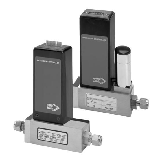
- Page 1 User’ s Guide Shop online at www.omega.com e-mail: info@omega.com FMA 1400 and FMA 1500 Mass Flow Meters and Controllers...
- Page 2 Toll Free in United Kingdom: 0800-488-48 FAX: +44 (0)161 777 6622 e-mail: sales@omega.co.uk It is the policy of OMEGA to comply with all worldwide safety and EMC/EMI regulations that apply. OMEGA is constantly pursuing certification of its products to the European New Approach Directives.
-
Page 3: Table Of Contents
2.1 Primary Gas Connections... 2.2 Electrical Connections... 3. PRINCIPLE OF OPERATION... 4. SPECIFICATIONS... 4.1 FMA 1500 Mass Flow Meters for ranges up to and above 10 L/min... 4.2 FMA 1400 Mass Flow Controllers for ranges up to and above 10 L/min... - Page 4 7.3 Linearity Adjustment... 7.3.1 Connections and Initial Warm Up... 7.3.2 ZERO Adjustment... 7.3.3 25% Flow Adjustment... 7.3.4 50% Flow Adjustment... 7.3.5 75% Flow Adjustment... 7.3.6 100% Flow Adjustment... 7.4 Calibration of FMA 1400 Mass Flow Controllers... 7.4.1 Disable Solenoid Valve... 7.4.2 Valve Adjustment...
- Page 5 Kalrez7 is a registered trademark of DuPont Dow Elastomers. Neoprene7 is a registered trademark of DuPont. TRADEMARKS Omega -is a registered trademark of Omega Engineering, Inc. ® VCR7 is a registered trademark of Crawford Fitting Co. Viton7 is a registered trademark of Dupont Dow Elastometers L.L.C.
-
Page 6: Unpacking The Fma 1400/1500 Mass Flow Meter
Packing List. Please report any shortages promptly. Returning Merchandise for Repair Please contact an Omega customer service representative and request a Return Authorization Number (AR). It is mandatory that any equipment returned for servicing be purged and neutral- ized of any dangerous contents including but not limited to toxic, bacterially infec- tious, corrosive or radioactive substances. -
Page 7: Electrical Connections
It is also preferable to install the FMA 1400/1500 transducer in a stable environment, free of frequent and sudden temperature changes, high moisture, and drafts. Prior to connecting gas lines inspect all parts of the piping system including fer- rules and fittings for dust or other contaminants. Be sure to observe the direction of gas flow as indicated by the arrow on the front of the meter when connecting the gas system to be monitored. - Page 8 FIGURE 2-1, WIRING DIAGRAM FOR FMA 1400/1500 TRANSDUCERS PIN FUNCTION Chassis Ground Common, Signal Ground For Pin 3 0-5 VDC Flow Signal +15 VDC Power Supply (-) 4-20 mA Flow Signal (optional) +7 VDC for Local Set Point (unassigned) TTL Valve Off Control (FMA 1400) Control Set Point Input 0 5 VDC (FMA 1400) Common, Signal Ground for Pin 9 Common, Power Supply...
-
Page 9: Principle Of Operation
Important notes: In general, "D" Connector numbering patterns are standardized. There are, how- ever, some connectors with nonconforming patterns and the numbering sequence on your mating connector may or may not coincide with the numbering sequence shown in our pin configuration table above. It is imperative that you match the appropriate wires in accordance with the correct sequence regardless of the par- ticular numbers displayed on your mating connector. -
Page 10: Specifications
FLOW MEDIUM: Please note that FMA 1400/1500 Mass Flow Meters and Controllers for ranges up to and above 10 L/min are designed to work with clean gases only. Never try to meter or control flow rates of liquids with any FMA 1500's or FMA 1400's. CALIBRATIONS: Performed at standard conditions [14.7 psia (1.01 bars) and 70... -
Page 11: Fma 1400 Mass Flow Controllers For Ranges Up To And Above 10 L/Min
Omega7 makes no expressed or implied guarantees of corrosion resistance of mass flow meters as pertains to different flow media reacting with components of meters. It is the customers' sole responsibility to select the model suitable for a particular gas based on the fluid contacting (wetted) materials offered in the different models. -
Page 12: Ce Compliance
[Cable length may not exceed 9.5 feet (3 meters)] CE Compliance Any model FMA 1500 or FMA 1400 bearing a CE marking on it, is in compliance with the below stated test standards currently accepted. EMC Compliance with 89/336/EEC as amended;... - Page 13 TABLE I FMA 1500/1400 FOR RANGES UP TO 10 L/MIN LOW FLOW MASS FLOW METER/CONTROLLERS* CODE TABLE II FMA 1500/1400 FOR RANGES ABOVE 10 L/MIN MEDIUM FLOW MASS FLOW METER/CONTROLLERS* CODE TABLE III FMA 1500/1400 FOR RANGES ABOVE 10 L/MIN...
-
Page 14: Operating Instructions
FMA 1500 up to 10 FMA 1400 MODEL FMA 1500 ranges up to 10 L/min transmitter FMA 1500 ranges above 10 L/min transmitter FMA 1400 ranges up to 10 L/min transmitter FMA 1400 ranges above 10 L/min transmitter OPERATING INSTRUCTIONS... -
Page 15: Flow Signal Output Readings
During initial powering of the FMA 1400/1500 transducer, the flow output signal will be indicating a higher than usual output. This is indication that the FMA 1400/1500 trans- ducer has not yet attained it's minimum operating temperature. This condition will automatically cancel within a few minutes and the transducer should eventually zero. -
Page 16: Ttl, Valve Off Control (Fma 1400)
age is a linear representation of 0 to 100% of the full scale mass flow rate. Response time to set point changes are 1 second (FMA 1400 for ranges up to 10 L/min) and 2 seconds (FMA 1400 for ranges above 10 L/min) to within 2% of the final flow over 25 to 100% of full scale. -
Page 17: Maintenance
To protect the instrument a 50 micron (FMA 1500/1400 for ranges up to 10 L/min) or 60 micron (FMA 1500/1400 for ranges above 10 L/min) filter is built into the inlet of the flow transducer. The filter screen and the flow paths may require occasional cleaning as described below. -
Page 18: Fma 1400/1500 Ranges Up To 10 L/Min
6.2.2 FMA 1400/1500 for ranges up to 10 L/min Unscrew the inlet compression fitting of meter. Note that the Restrictor Flow Element (RFE) is connected to the inlet fitting. Carefully disassemble the RFE from the inlet connection. The 50 micron filter screen will now become visible. -
Page 19: Calibration Procedures
Contact Omega7 for optional sealing materials available. Set the FMA 1400 into PURGE mode, and attempt to flush through with a clean, filtered, and neutral gas such as nitrogen. [Another option for fully opening the valve is to remove the plastic cap on top of the valve, and turn the set screw coun- terclockwise until it stops. -
Page 20: Calibration Of Fma 1500 Mass Flow Meters
All adjustments in this section are made from the outside of the meter, there is no need to disassemble any part of the instrument. FMA 1500 Mass Flow Meters may be field recalibrated/checked for the same range they were originally factory calibrated for. When linearity adjustment is needed, or flow range changes are being made proceed to step 7.3. -
Page 21: Zero Adjustment
LIKELY REASONS FOR A MALFUNCTIONING SIGNAL MAY BE: M Occluded or contaminated sensor tube. M Leaking condition in the FMA 1500 transducer or the gas line and fittings. M For gases other than nitrogen, recheck appropriate "K" factor from Gas Factor Table. -
Page 22: Zero Adjustment
7.3.2 ZERO Adjustment Shut off the flow of gas into the Mass Flow Meter. To ensure that no seepage or leak occurs into the meter, it is good practice to temporarily disconnect the gas source. Using the multimeter and the insulated screwdriver, adjust the ZERO potentiometer [R29] through the access window for 0 VDC (or 4 mA respectively) at zero flow. -
Page 23: Valve Adjustment
the transducer. The unit will now act as a mass flow meter. CAUTION: If the valve is left in the AUTO (control) or OPEN mode for an extended period of time, it may become warm or even hot to the touch. Use care in avoiding direct contact with the valve during operation. -
Page 24: Troubleshooting
TABLE VI FMA 1400 SOLENOID VALVE ORIFICE SELECTION TABLE ORIFICE PART NUMBER OR.010 OR.020 OR.040 OR.055 OR.063 OR.073 OR.094 OR.125 TROUBLESHOOTING Common Conditions Your Mass Flow Meter/Controller was thoroughly checked at numerous quality control points during and after manufacturing and assembly operations. It was cal- ibrated in accordance to your desired flow and pressure conditions for a given gas or a mixture of gases. -
Page 25: Troubleshooting Guide
Troubleshooting Guide INDICATION LIKELY REASON lack of power supply off reading or fuse blown output (FMA 1400/1500) fuse blown (FMA14PD Series) filter screen obstructed at inlet occluded sensor tube pc board defect valve adjustment wrong output reads fuse blown (FMA 1400/1500) at (+) or (- ) saturation only... - Page 26 INDICATION LIKELY REASON gas leak unstable or no zero reading pc board defective full scale out- put at "no flow" defective sensor condition or gas Leak with valve closed calibration off gas metered is not the same as what meter was calibrated for composition of gas changed gas leak pc board defective...
-
Page 27: Technical Assistance
For best results it is recommended that instruments are returned to the factory for servicing. See section 1.3 for return procedures. Technical Assistance Omega7 Engineering will provide technical assistance over the phone to qualified repair personnel. Please call our Flow Department (800) 872-9436 extension 2298. -
Page 28: Appendix 1 Component Diagrams
APPENDIX 1 COMPONENTS DIAGRAMS FMA 1500 METERING PC BOARD FMA 1400 CONTROL PC BOARD (ALSO INCORPORATED IN FMA 1400) -
Page 29: Appendix 2 Gas Factor Table ("K" Factors)
GAS FACTOR TABLE (“K” FACTORS) ACTUAL GAS Acetylene C Allene (Propadiene) C Ammonia NH Argon Ar Arsine AsH Boron Trichloride BCl Boron Triflouride BF Bromine Br Boron Tribromide Br Bromine Pentaflouride BrF Bromine Triflouride BrF Bromotrifluoromethane (Freon-13 B1) CBrF 1,3-Butadiene C Butane C 1-Butane C 2-Butane C... - Page 30 ACTUAL GAS Dibromodifluoromethane CBr Dichlorodifluoromethane (Freon-12) CCl Dichlofluoromethane (Freon-21) CHCl Dichloromethylsilane (CH Dichlorosilane SiH Dichlorotetrafluoroethane (Freon-114) C 1,1-Difluoroethylene (Freon-1132A) C Dimethylamine (CH Dimethyl Ether (CH 2,2-Dimethylpropane C Ethane C Ethanol C Ethyl Acetylene C Ethyl Chloride C Ethylene C Ethylene Oxide C Fluorine F Fluoroform (Freon-23) CHF Freon-11 CCl...
- Page 31 Actual Gas Hydrogen Fluoride HF Hydrogen Iodide HI Hydrogen Selenide H Hydrogen Sulfide H Iodine Pentafluoride IF Isobutane CH(CH Isobutylene C Krypton Kr Methane CH Methanol CH Methyl Acetylene C Methyl Bromide CH Methyl Chloride CH Methyl Fluoride CH Methyl Mercaptan CH Methyl Trichlorosilane (CH Molybdenum Hexafluoride MoF Monoethylamine C...
- Page 32 Actual Gas Phosphorous Trichloride PCl Propane C Propylene C Silane SiH Silicon Tetrachloride SiCl Silicon Tetrafluoride SiF Sulfur Dioxide SO Sulfur Hexafluoride SF Sulfuryl Fluoride SO Tetrafluoroethane (Forane 134A) CF Tetrafluorohydrazine N Trichlorofluoromethane (Freon-11) CCl Trichlorosilane SiHCl 1,1,2-Trichloro-1,2,2 Trifluoroethane (Freon-113) CCl FCClF Triisobutyl Aluminum (C Titanium Tetrachloride TiCl...
-
Page 33: Appendix 3 Dimensional Drawings
APPENDIX 3 DIMENSIONAL DRAWINGS FMA 1500 FOR RANGES UP TO 10 L/MIN MASS FLOW METER NOTES: Omega7 reserves the right to change designs and dimensions at its sole discretion at any time without notice. For certified dimensions please contact Omega7. - Page 34 FMA 1500 FOR RANGES ABOVE 10 L/MIN MASS FLOW CONTROLLER NOTES: Omega7 reserves the right to change designs and dimensions at its sole discretion at any time without notice. For certified dimensions please contact Omega7.
- Page 35 FMA 1400 RANGES UP TO 10 L/MIN MASS FLOW CONTROLLER NOTES: Omega7 reserves the right to change designs and dimensions at its sole discretion at any time without notice. For certified dimensions please contact Omega7.
- Page 36 FMA 1400 RANGES ABOVE 10 L/MIN MASS FLOW CONTROLLER NOTES: Omega7 reserves the right to change designs and dimensions at its sole discretion at any time without notice. For certified dimensions please contact Omega7.
- Page 37 NOTES:...
- Page 38 NOTES:...
-
Page 39: Appendix 4 Warranty
Department will issue an Authorized Return (AR) number immediately upon phone or written request. Upon examination by OMEGA, if the unit is found to be defective, it will be repaired or replaced at no charge. OMEGA’s WARRANTY does not apply to defects resulting from any action of the purchaser, including but not limited to mishandling, improper interfacing, operation outside of design limits, improp- er repair, or unauthorized modification. -
Page 40: Data Acquisition
Where Do I Find Everything I Need for Process Measurement and Control? OMEGA…Of Course! Shop online at www.omega.com TEMPERATURE Thermocouple, RTD & Thermistor Probes, Connectors, Panels & Assemblies Wire: Thermocouple, RTD & Thermistor Calibrators & Ice Point References Recorders, Controllers & Process Monitors...