
Related Manuals for Omega FMA1800A


Summary of Contents for Omega FMA1800A
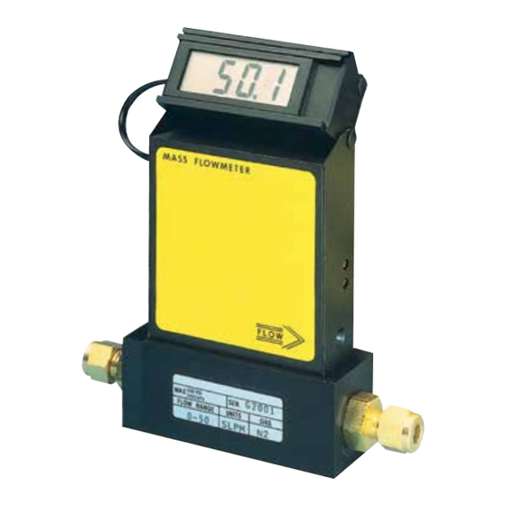
- Page 1 User’s Guide Shop online at omega.com e-mail: info@omega.com For latest product manuals: www.omegamanual.info NORWALK, CT FMA1700A & FMA1800A Mass Flow Meter...
- Page 2 Fax: (203) 359-7700 e-mail: info@omega.com For Other Locations Visit omega.com/worldwide The information contained in this document is believed to be correct, but OMEGA accepts no liability for any errors it contains, and reserves the right to alter specifications without notice.
-
Page 3: Table Of Contents
TABLE OF CONTENTS 1. UNPACKING THE FMA1700A/1800A MASS FLOW METER..... Inspect Package for External Damage..........Unpack the Mass Flow Meter............... Returning Merchandise for Repair............2. INSTALLATION..................Primary Gas Connections..............Electrical Connections..............2.3.1 Remote LCD Readouts..............2.3.2 Panel Mounting Readouts..............3. PRINCIPLE OF OPERATION..............4. - Page 4 7.3.6 50% Flow Adjustment..............7.3.7 75% Flow Adjustment..............7.3.8 100% Flow Adjustment..............LCD Display Scaling................. 7.4.1 Access LCD Display Circuit.............. 7.4.2 Adjust Scaling.................. 7.4.3 Change Decimal Point..............8. TROUBLESHOOTING................Common Conditions................ Troubleshooting Guide..............Technical Assistance............... 9. CALIBRATION CONVERSIONS FROM REFERENCE GASES....... APPENDIX 1 COMPONENT DIAGRAM............
-
Page 5: Unpacking The Fma1700A/1800A Mass Flow Meter
Unpack the Mass Flow Meter CAUTION: Some of the IC devices used in the FMA1700A & FMA1800A are Electro Static Discharge (ESD) sensitive and may be damaged by improper handling. When wiring interface connector, adjusting or servicing the meter, use of a grounded ESD protection wrist strap is required to prevent inadvertent damage to the CMOS integral solid state circuitry. -
Page 6: Electrical Connections
See specifications in this manual.) Electrical Connections CAUTION: Some of the IC devices used in the FMA1700A & FMA1800A are Electro Static Discharge (ESD) sensitive and may be damaged by improper handling. When wiring interface connector, adjusting or servicing the meter, use of a grounded ESD protection wrist strap is required to prevent inadver tent damage to the CMOS integral solid state circuitry. - Page 7 The FMA1700A & FMA1800A flow meters have universal power input and can be used with any power supply voltage between +12 and +26 Vdc. CAUTION: BEFORE CONNECTING POWER SUPPLY CHECK YOUR METER SERIAL NUMBER AND POWER SUPPLY REQUREMENTS LABEL LOCATED ON THE FLOW METER BACK COVER.
-
Page 8: Remote Lcd Readouts
The power input is protected by 300 mA M (medium time-lag) resettable fuse. If a shorting condition or polarity reversal occurs, the fuse will cut power to the flow transducer circuit. Disconnect the power to the unit, remove the faulty condition, and reconnect the power. -
Page 9: Principle Of Operation
PRINCIPLE OF OPERATION The stream of gas entering the Mass Flow transducer is split by shunting a small portion of the flow through a capillary stainless steel sensor tube. The remainder of the gas flows through the primary flow conduit. The geometry of the primary con- duit and the sensor tube are designed to ensure laminar flow in each branch. -
Page 10: Specifications
RS232 or RS485 interfaces. TRANSDUCER INPUT POWER: FMA1700A & FMA1800A models with universal power input between +12 and +25 VDC, 200 mA maximum; Power input is protected by a 300 mA M (medium time-lag) resettable fuse, and a rectifier... -
Page 11: Ce Compliance
WETTED MATERIALS: FMA1700A/1800A Series Max Flow 15, 50, 100, 200, 500 and 1000 L/min: Anodized aluminum, brass, and 316 stainless steel with FKM O-rings seals; BUNA, EPR or Perfluoroelastomer O-rings are optional. FMA1700A/1800A Series Max Flow 15, 50, 100, 200, 500 and 1000 L/min: 316 stain- less steel with FKM O-rings seals;... - Page 12 FLOW RANGES TABLE I FMA1700A/1800A TABLE II FMA1700A/1800A SERIES MAX FLOW 15 L/min SERIES MAX FLOW 50 L/min LOW FLOW MASS FLOW METER* MEDIUM FLOW MASS FLOW METER* mL/min [N CODE CODE L/min [N 0 to 10 0 to 20 0 to 50 0 to 100 0 to 200...
-
Page 13: Operating Instructions
OPERATING INSTRUCTIONS Preparation and Warm Up It is assumed that the Mass Flow Meter has been correctly installed and thor- oughly leak tested as described in section 2. Make sure the flow source is OFF. Apply power to the unit by plugging the power supply line into the DC power jack (or 9-pin 'D' connector) on the side of the meter. -
Page 14: Swamping Condition
Swamping Condition If a flow of more than 10% above the maximum flow rate of the Mass Flow Meter is taking place, a condition known as “swamping” may occur. Readings of a “swamped” meter cannot be assumed to be either accurate or linear. Flow must be restored to below 110% of maximum meter range. -
Page 15: Fma1700A/1800A Series Max. Flow 15 L/Min
6.2.2 FMA1700A/1800A Series Max Flow 15 L/min models Unscrew the inlet compression fitting of meter. Note that the Restrictor Flow Element (RFE) is connected to the inlet fitting. Carefully disassemble the RFE from the inlet connection. The 50 micron filter screen will now become visible. - Page 16 This practice is recommended when a reference gas is found with thermodynamic properties similar to the actual gas under consideration. The appropriate relative correction factor should be recalculated - see section 9. It is standard practice to calibrate Mass Flow Meters with dry nitrogen gas at 70 F (21.1 C), 20 psig (1.4 bars) inlet pressure and 0 psig (0 bar) outlet pressure.
-
Page 17: Calibration Of Fma1700A/1800A Mass Flow Meters
Calibration of FMA1700A/1800A Mass Flow Meters All adjustments in this section are made from the outside of the meter, there is no need to disassemble any part of the instrument. FMA1700A/1800A Mass Flow Meters may be field recalibrated/checked for the same range they were originally factory calibrated for. -
Page 18: Linearity Adjustment
7.3.1 Connections and Initial Warm Up At the 9-pin “D” connector of the FMA1700A & FMA1800A transducer, connect the multimeter to output pins [2] and [3] for 0-5 VDC (or pins [8] and [9] for 4-20 mA)-(see Figure 2.a). If calibration to a new flow range or different gas is being performed, it may be necessary to remove any jumpers at J1.A, J1.B, J1.C, and... -
Page 19: 10% Flow Adjustment
7.3.4 10% Flow Adjustment Using the flow regulator, adjust the flow rate to 10% of full scale flow according to the calibrator. Check the flow rate indicated against the flow calibrator. Adjust the setting for potentiometer [R33] by using the insulated screwdriver through the access win- dow, until the output of the flow meter reads 0.5VDC ±63mV (or 5.6mA ±0.25mA). -
Page 20: Access Lcd Display Circuit
7.4.1 Access LCD Display Circuit Carefully remove the LCD from the FMA1700A/1800A or panel mounted surface. Remove the aluminum housing on the side of the connection cable. Slide the LCD assembly out of the aluminum housing. 7.4.2 Adjust Scaling Using a digital multimeter connected to either the 0 to 5 VDC or 4 to 20 mA sig- nal at the 9-pin “D”... -
Page 21: Troubleshooting Guide
Troubleshooting Guide INDICATION LIKELY REASON REMEDY Lack of reading or output. Power supply off Check connection of power supply. Fuse blown Disconnect FMA1700A/1800A transducer from power supply; remove the shorting condition or check polarities; fuse resets automatically. Filter screen Flush clean or disassemble obstructed at inlet. - Page 22 INDICATION LIKELY REASON REMEDY No zero reading after 15 Embedded temperature has Readjust ZERO minute warm up time and no been changed. potentiometer R34 through flow condition. the access hole (see page 13 for details). No zero reading after 15 Power supply voltage is Measure voltage on pins minute warm up time and no...
- Page 23 INDICATION LIKELY REASON REMEDY LCD Display reading does LCD Display is adjusted for Readjust LCD Display not correspond the correct wrong flow range or scaling for required full scale flow range according analog engineering units. flow (see 7.4 on page 15). output 0-5 Vdc signal.
- Page 24 LIKELY REASON INDICATION REMEDY LCD Display reading is Sensor under swamping Lower the flow through conditions (flow is more above maximum flow range FMA1700A/1800A within than 10% above maximum and output voltage 0-5 Vdc calibrated range or shut flow rate for particular signal is more than 5.5 Vdc down the flow completely.
-
Page 25: Technical Assistance
INDICATION LIKELY REASON REMEDY Sensor or PC board is FMA1700A/1800A is Return FMA1700A/1800A to disconnected from the defective. factory for repair. source of the gas (no flow conditions) but LCD Display reading is fluctuating in wide range. Output voltage 0-5 Vdc signal also fluctuating. -
Page 26: Calibration Conversions From Reference Gases
CALIBRATION CONVERSIONS FROM REFERENCE GASES The calibration conversion incorporates the K factor. The K factor is derived from gas density and coefficient of specific heat. For diatomic gases: d X C where d = gas density (gram/liter) = coefficient of specific heat (cal/gram) Note in the above relationship that d and Cp are usually chosen at the same con- ditions (standard, normal or other). -
Page 27: Appendix 1 Component Diagram
APPENDIX 1 COMPONENTS DIAGRAM FMA1700A/1800A METERING PC BOARD... -
Page 28: Appendix 2 Gas Factor Table ("K" Factors)
APPENDIX 2 GAS FACTOR TABLE (“K” FACTORS) CAUTION: K-Factors at best are only an approximation. K factors should not be used in applications that require accuracy better than +/- 5 to 10%. K FACTOR Density ACTUAL GAS Relative to N [Cal/g] [g/I] Acetylene C... - Page 29 K FACTOR Density ACTUAL GAS Relative to N [Cal/g] [g/I] Deuterium D 1.00 1.722 1.799 Diborane B .4357 .508 1.235 Dibromodifluoromethane CBr .1947 9.362 Dichlorodifluoromethane (Freon-12) CCl .3538 .1432 5.395 Dichlofluoromethane (Freon-21) CHCl .4252 .140 4.592 Dichloromethylsilane (CH SiCl .2522 .1882 5.758 Dichlorosilane SiH...
- Page 30 K FACTOR Density ACTUAL GAS Relative to N [Cal/g] [g/I] 1.000 .0861 3.610 Hydrogen Bromide HBr 1.000 .1912 1.627 Hydrogen Chloride HCl .764 .3171 1.206 Hydrogen Cyanide HCN .9998 .3479 .893 Hydrogen Fluoride HF .9987 .0545 5.707 Hydrogen Iodide HI Hydrogen Selenide H .7893 .1025...
- Page 31 K FACTOR Density ACTUAL GAS Relative to N [Cal/g] [g/I] Phosphorous Oxychloride POCl .1324 6.843 Phosphorous Pentafluoride PH .3021 .1610 5.620 Phosphorous Trichloride PCl .1250 6.127 Propane C .399 1.967 Propylene C .366 1.877 Silane SiH .5982 .3189 1.433 Silicon Tetrachloride SiCl .284 .1270 7.580...
-
Page 32: Appendix 3 Dimensional Drawings
APPENDIX 3 DIMENSIONAL DRAWINGS 2.38 NO LCD 0.95 VERSION FLOW DASHED LINE FOR HIGH FLOW UNITS DIMENSION (INCH) CONNECTION Compression Fitting MAXIMUM FLOW LCD VERSION (Except Model SERIES FMA1700A/1800A Series Max Flow C/*C D/*D E/*E 1000 L/min) ¹/₄" Tube O Diameter 10 L/min 5.60 1.00... -
Page 33: Parts Of The Flow Meter
PARTS OF THE FLOW METER LEFT AND RIGHT VIEWS FRONT VIEW... - Page 34 NOTES:...
- Page 35 OMEGA be liable for consequential, incidental or special damages. CONDITIONS: Equipment sold by OMEGA is not intended to be used, nor shall it be used: (1) as a “Basic Component” under 10 CFR 21 (NRC), used in or with any nuclear installation or activity;...
- Page 36 Where Do I Find Everything I Need for Process Measurement and Control? OMEGA…Of Course! Shop online at omega.com TEMPERATURE M U Thermocouple, RTD & Thermistor Probes, Connectors, Panels & Assemblies M U Wire: Thermocouple, RTD & Thermistor M U Calibrators & Ice Point References M U Recorders, Controllers &...