Table of Contents
Advertisement
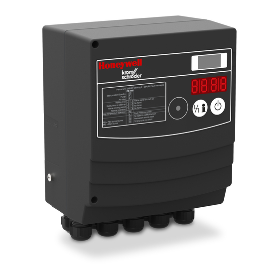
Burner control units BCU 460, BCU 465
Technical Information · GB
6 Edition 11.19
• For burners in intermittent operation or in continuous operation
• Flame control by UV, ionization or a further option of using the
furnace chamber temperature
• Simple system integration using the PC programming and
diagnostic software BCSoft
• With optional valve proving system
• With optional operating modes to reduce thermal NOx
• Fieldbus connection (PROFIBUS, PROFINET, EtherNet/IP) using
optional bus module
Advertisement
Table of Contents

Related Manuals for Honeywell BCU 460


Summary of Contents for Honeywell BCU 460
-
Page 1: Burner Control Units Bcu 460, Bcu 465
Burner control units BCU 460, BCU 465 Technical Information · GB 6 Edition 11.19 • For burners in intermittent operation or in continuous operation • Flame control by UV, ionization or a further option of using the furnace chamber temperature •... -
Page 2: Table Of Contents
Contents Burner control units BCU 460, BCU 465 . . . . . . . . . . . . . 1 3.3 BCU 460 program sequence ....30 3.4 BCU 465 program sequence . - Page 3 11.16.12 Function of input 39 ......116 11.10 Behaviour during start-up....102 BCU 460, BCU 465 · Edition 11.19 ▼...
- Page 4 23.11 Air actuator........143 16.3 Electrical connection ......129 BCU 460, BCU 465 · Edition 11.19 ▼...
- Page 5 Contact . . . . . . . . . . . . . . . . . . . . . . . . . . . . . . . . . . . . . . . . . . . 145 BCU 460, BCU 465 · Edition 11.19 ▼...
-
Page 6: Application
▼ It can be used for directly ignited industrial burners of unlimited capacity. The burners may be modulating- controlled or stage-controlled. Installation in the imme- BCU 460, BCU 465 · Edition 11.19... - Page 7 If necessary, the device parameters can be adjusted easily using BCSoft. All valid parameters are saved on an integrated param- eter chip card. The parameter chip card can be removed BCU 460, BCU 465 · Edition 11.19...
-
Page 8: Application Examples
The gas/air mixture is adjusted to the requirements of the applications using the parameters of pre-ventila- tion and post-ventilation. The pressure switch moni- tors the air flow in the air supply line or in the flue gas exhaust. BCU 460, BCU 465 · Edition 11.19... -
Page 9: Profinet Connection Using Bus Module Bcm
Control signals that are relevant for safety, such as the safety interlocks, purge and HT input, are wired inde- pendently of the bus communication using separate cables. BCU 460, BCU 465 · Edition 11.19... -
Page 10: Staged Control
BCU and the butterfly valve BVA is set to the pre-purge position. In the event of a temperature demand, the burner con- trol unit BCU activates input DI 1 via the output at ter- BCU 460, BCU 465 · Edition 11.19... -
Page 11: Modulating Control With Defined Ignition Position
DI 2 is activated via the air valve output of the BCU and the butterfly valve BVA is set to the pre-purge position. In the event of a temperature demand, the burner con- trol unit BCU activates input DI 1 via the output at ter- BCU 460, BCU 465 · Edition 11.19... -
Page 12: Two-Stage-Controlled Burner
VAS 1 VR..L Control: ON/OFF or High/Low The BCU provides the cooling and purging processes. Parameter A078 = 4 is selected so that the two-stage burner starts at low-fire rate. When the operating state BCU 460, BCU 465 · Edition 11.19... -
Page 13: Single-Stage-Controlled Burner With Pneumatic
Optional: the pressure switch monitors the air flow during pre-purge and operation. The gas/air mixture is adjusted to the requirements of the application using the parameters of pre-ventilation and post-ventilation. BCU 460, BCU 465 · Edition 11.19... -
Page 14: Flame Control Using The Temperature
HT output that the furnace system is in High temperature mode (HT). When the HT input is activated, the burner control units switch to High temperature mode. They operate without evaluat- BCU 460, BCU 465 · Edition 11.19... -
Page 15: Flameless Mode To Reduce No Formation
In addition, air/gas ratio monitor- ing for the zone or the furnace is required. As soon as the safety temperature monitor STM signals a furnace temperature of ≥ 850°C (1562°F), the burner BCU 460, BCU 465 · Edition 11.19... -
Page 16: On/Off Rotary Impulse Control
In this type of control, >750° LM..F3 the burner output pulse frequency FCU 500..F0 always maintains full momentum 47 48 and results in maximum convection Purge in the furnace chamber, even with regulated heating. ▼ VR..L BCU 460, BCU 465 · Edition 11.19... - Page 17 ϑ VR..L test, flow detector and pressure µC BCU 460/ switch check (gas , gas min. max. >750° LM..F3 ) are provided by the FCU 500. FCU 500..F0 min. 47 48 Purge VR..L BCU 460, BCU 465 · Edition 11.19...
-
Page 18: Modulating Burner Control
LDS outputs on the FCU and the corresponding in- puts on the BCUs ensures that the burners can only start if the safety interlocks and the LDS output have enabled burner start-up. BCU 460, BCU 465 · Edition 11.19... -
Page 19: Certification
– (EU) 2016/426 (GAR), Gas Appliances Regulation – EN 13611:2015+AC:2016 – EN 1854:2010, class S FM approved Factory Mutual (FM) Research Class: 7610 “Combus- tion Safeguards and Flame Sensing Systems”. Suitable for applications pursuant to NFPA 86. www.approvalguide.com BCU 460, BCU 465 · Edition 11.19... -
Page 20: Function
BCU type label Power module, replaceable Power module type label Parameter chip card (PCC), replaceable Bus module, replaceable M5 screw terminal for burner ground There are two control keys for the control unit: BCU 460, BCU 465 · Edition 11.19... -
Page 21: Connection Diagram
92 91 90 95 96 97 (BCU..E0) (BCU..E1) F 3,15 A LM 400..F0 F3 3,15 A UA-Sk 51 21 BM 52 53 BM 54 24 55 25 56 26 60 30 61 31 62 32 BCU 460, BCU 465 · Edition 11.19... -
Page 22: Bcu 460
95 96 97 (BCU..E0) LM 400..F3 (BCU..E1) F 3,15 A F3 3,15 A UA-Sk Luft 51 21 BM 52 53 BM 54 24 55 25 56 26 60 30 61 31 62 32 65 34 BCU 460, BCU 465 · Edition 11.19... -
Page 23: Bcu 465
(BCU..E1) F 3,15 A F3 3,15 A UA-Sk Luft 51 21 BM 52 53 BM 54 24 55 25 56 26 60 30 61 31 62 32 65 34 DW 1 DW 2 BCU 460, BCU 465 · Edition 11.19... -
Page 24: Bcu 460
92 91 90 95 96 97 (BCU..E0) (BCU..E1) F 3,15 A LM 400..F0 F3 3,15 A UA-Sk 51 21 BM 52 53 BM 54 24 55 25 56 26 60 30 61 31 62 32 BCU 460, BCU 465 · Edition 11.19... -
Page 25: Bcu 460
95 96 97 (BCU..E0) LM 400..F3 (BCU..E1) F 3,15 A F3 3,15 A UA-Sk Luft 51 21 BM 52 53 BM 54 24 55 25 56 26 60 30 61 31 62 32 65 34 BCU 460, BCU 465 · Edition 11.19... -
Page 26: Bcu 465
(BCU..E1) F 3,15 A F3 3,15 A UA-Sk Luft 51 21 BM 52 53 BM 54 24 55 25 56 26 60 30 61 31 62 32 65 34 DW 1 DW 2 BCU 460, BCU 465 · Edition 11.19... -
Page 27: Flame Control
Ionization control in single-electrode operation Parameter I004 = 0. 54 24 PE UVC 1 51 21 BM PE UVS control Parameter A001 ≥ 5 �A. Parameter I004 = 1. 51 21 BM PE BCU 460, BCU 465 · Edition 11.19... -
Page 28: Assignment Of Connection Terminals
Connection for sensor 2 with pilot lamp to monitor the air pressure (AC mains voltage) Connection for the sensor of the valve proving system (tightness control pressure switch or POC switch for checking the closed position) 59, 38 Valve proving system ▼ BCU 460, BCU 465 · Edition 11.19... - Page 29 Contact between terminals 95 and 97 closes once the operating signal has been received 96, 97 Floating contact from burner 2. Parameter-dependent function Contact can be adjusted depending on parameter I054 86, 87 90, 91 Parameter-dependent function Contact can be adjusted depending on parameter I051 BCU 460, BCU 465 · Edition 11.19...
-
Page 30: Bcu 460 Program Sequence
Safety time 1 t (A094) running, ignition in process, valves for 1 gas stage open and min. operating time starts to elapse (A061) ▼ If no flame detected: max. 3 start-up attempts (A007) or fault lock-out BCU 460, BCU 465 · Edition 11.19... -
Page 31: Bcu 465 Program Sequence
Pre-ventilation time after safety shut-down running (A036) ▼ In the event of flame failure: pre-purge running restart or fault lock-out ▼ Min. pause time running again (parameter A062) ▼ Flame simulation check (if parameter A003 = 1) ▼ ▼ BCU 460, BCU 465 · Edition 11.19... - Page 32 If min. operating time t has elapsed: operation signalling contact opens, gas valves close and running time (A042) starts to elapse ▼ Over-run time (post-ventilation) t running (A039) Air actuator is closed, running time starts to elapse (A042) BCU 460, BCU 465 · Edition 11.19...
-
Page 33: Air Control
The capacity is controlled during operation by an external temperature control system. BCU/LM..F3 BCU/LM..F3 ϑ VR..L µC µC BCU/LM..F3 BCU/LM..F3 >750° >750° FCU 500..F0 FCU 500 47 48 Purge Purge VR..L BCU 460, BCU 465 · Edition 11.19... -
Page 34: Capacity Control
As soon as there is a purge signal at terminal 3 of BCU, page 93 (Air actuator control). the control element is activated by the outputs for ca- pacity control to approach the position for pre-purge. BCU 460, BCU 465 · Edition 11.19... -
Page 35: Bcu 460
As soon as there is a purge signal at terminal 3 of BCU.. F3, the air valve is activated by the output at terminal 65. The protective system (FCU 500) starts the pre- purge time if there is adequate air flow. After the elapse BCU 460, BCU 465 · Edition 11.19... -
Page 36: Low No Mode (Flameless Operation)
Burners BIC..M are tailored to the appropriate capacity and combined with tapered IC 40 + BVH ceramic tubes (TSC..M). ▼ BCU 460, BCU 465 · Edition 11.19... - Page 37 For further information on burner BIC..M, see www.docuthek.com Gas and air are supplied via the same connections as in Flame mode. No ignition takes place in the burner tube. BCU 460, BCU 465 · Edition 11.19...
-
Page 38: Bcu 460
850°C is required for flameless operation. Flameless mode is enabled via the input at terminal 7: depending on parameter A064, the system is either switched over immediately or the next time the BCU 460, BCU 465 · Edition 11.19... - Page 39 Hot air compensation and ratio control are not the re- sponsibility of the BCU . These functions must satisfy the requirements of a protective system pursuant to EN 746-2 and be implemented externally. BCU 460, BCU 465 · Edition 11.19...
-
Page 40: Valve Proving System
1200 kW (NFPA 86: from 117 kW or 400,000 Btu/h). The tightness control function satisfies the require- ments of EN 1643 (Valve proving systems for automat- ic shut-off valves for gas burners and gas appliances). BCU 460, BCU 465 · Edition 11.19... -
Page 41: Test Instant
This ensures µC that the test volume V can be vented during the tight- ness test with the air/gas ratio control closed. 36 37 BCU 460, BCU 465 · Edition 11.19... -
Page 42: Program Sequence
V2 is around atmospheric pres- – p Z > p Z > sure and the volume downstream of V2 is at least 5 × – higher than the volume between the valves. ▼ BCU 460, BCU 465 · Edition 11.19... - Page 43 V2 is at least 5 × higher than the volume between the valves. t L = A059 t L = A059 t M = A056 t M = A056 – p Z > p Z > – BCU 460, BCU 465 · Edition 11.19...
-
Page 44: Test Period T
3 s for the tightness test if the main gas valves are actuated directly. If gas can flow into the combus- tion chamber when a valve is opened, the gas volume must not exceed 0.083% of the maximum flow rate. BCU 460, BCU 465 · Edition 11.19... -
Page 45: Measurement Time T
Adjustable using parameter A056 2 x p [s] = For a large test volume V with reduced testing time Adjustable using parameter A056 0.9 x p [s] = Conversion into US units, see page 136 (Converting units) BCU 460, BCU 465 · Edition 11.19... - Page 46 VG 10 0.01 VG 15 0.07 VG 20 0.12 12.3 VG 25 17.7 VG 40/VK 40 31.4 VG 50/VK 50 VG 65/VK 65 VG 80/VK 80 VK 100 VK 125 13.6 VK 150 BCU 460, BCU 465 · Edition 11.19...
- Page 47 BCU 570..C1 Leakage rate = 200 l/h 47 48 1000 x 1 m Test volume V = 1.1 l + 9.5 m x 3.3 l/m = 32.45 l, see page 46 (Test volume Vp1) BCU 460, BCU 465 · Edition 11.19...
-
Page 48: Proof Of Closure Function
By checking the closed position using the proof of clo- >750° sure function, the BCU complies with the requirements BCU 46x..C1 of NFPA 85 (Boiler and Combustion Systems Hazards Code) and NFPA 86 (Standard for Ovens and Furnaces). BCU 460, BCU 465 · Edition 11.19... -
Page 49: Bcsoft
In the event of faults or service interventions, details on troubleshooting can be derived from the device statistics and the fault history. BCU 460, BCU 465 · Edition 11.19... -
Page 50: Fieldbus Communication
PROFINET The basic function of fieldbus communication is the exchange of process and required data between a con- troller (e.g. a PLC) and several distributed devices (e.g. BCM with BCU). BCU 460, BCU 465 · Edition 11.19... -
Page 51: Bcu And Bus Module Bcm
For information on planning and the structure of a net- work and the components to be used (e.g. cables, lines and switches) for PROFINET and PROFIBUS, see www.profibus.com, for EtherNet/IP, see www.odva.org. BCU 460, BCU 465 · Edition 11.19... -
Page 52: Configuration, Planning
The GSD/EDS file for the bus module can be obtained from www.docuthek.com. The steps required to integrate the file are described in the instructions for the engineering tool for your automation system. BCU 460, BCU 465 · Edition 11.19... -
Page 53: Profinet, Ethernet/Ip
Outputs (PLC ➔ BCU) Burner 1 flame signal Burner 2 flame signal Status signal Fault and warning signals Remaining times Temperature Input information (via terminal and bus) Output information (via terminal and bus) ▼ BCU 460, BCU 465 · Edition 11.19... - Page 54 Terminals 1 to 41 (dependent on parameters I061 to I074) can be wired parallel to the bus communication. This allows the BCU to be controlled using the digital signals of the bus communication or the inputs at the terminals. BCU 460, BCU 465 · Edition 11.19...
- Page 55 The flame signal occupies one byte with values from 0 to 255 (= flame signal from 0 to 25.5 µA). Bit Byte n Data type Format Value 0 – 255 Burner 2 flame signal Byte (0 – 25.5 μA) See code tables “BusCommunication_BCU4_R2.xlsx” at www. docuthek.com. BCU 460, BCU 465 · Edition 11.19...
- Page 56 Byte n+3 Data type Format Value Bit Byte n Byte n+1 Data type Format Value Warning signals Word 0 – 655535 0 – 6554 Temperature Word (0 – 6554 K) See code tables “BusCommunication_BCU4_R2.xlsx” at www. docuthek.com. ▼ BCU 460, BCU 465 · Edition 11.19...
- Page 57 BOOL Terminal 66 Free Free BCU ON Burner 1 flame Free BOOL Terminal 67 Free Free Manual mode Burner 2 flame Free BOOL 1) Only with BCU 465 depending on the parameter settings. BCU 460, BCU 465 · Edition 11.19...
-
Page 58: Device Parameters And Statistics
Operator statistics, extreme values 1011 Operator statistics, time counters The available data records differ in terms of their indexes. The contents and description of the indexes are described in the code table “BusCommunication_BCU4_R2.xlsx” (download from www.docuthek.com). BCU 460, BCU 465 · Edition 11.19... -
Page 59: Profibus
The specified ranges relate to bus cable type A (2-core, Byte 0 shielded and twisted), e.g. Reset Siemens, Order No. 6XV1830-0EH10, or Start 1 Lapp cable unitronic, Order No. 2170-220T. Cooling Purge Free Free Free Free BCU 460, BCU 465 · Edition 11.19... -
Page 60: Program Step/Status
Burner 1 operation/controller enable (with air) Over-run up to minimum capacity Post-purge Data transfer (programming mode) – – Device Off In Manual mode, four dots flash on the display. Air actuator (control element/valve) is open. BCU 460, BCU 465 · Edition 11.19... -
Page 61: Fault Signalling
E 40 Inlet valve(s) leaking Leak found on inlet valve E 41 Outlet valve(s) leaking Leak found on outlet valve E 44 Pressure switch/gas valve wiring E 45 Gas valve wiring Reversed valve connection BCU 460, BCU 465 · Edition 11.19... - Page 62 Fault Air monitor “no flow” state check. The signal from the Air monitor “no flow” state pressure switches is received at terminal 36 or 37 before the air actuator is opened. Low air pressure Fault Air monitor operating check BCU 460, BCU 465 · Edition 11.19...
- Page 63 Flame failure during flame proving period 1 while air actuator is E A3 Flame failure during flame proving period 1 open E A4 Flame failure during burner 1 operation Flame failure during burner 1 operation while air actuator is open BCU 460, BCU 465 · Edition 11.19...
-
Page 64: Parameters
Time in seconds Pre-ventilation/flameless A028 0 – 250 Time in seconds Pre-purge time tPV A034 0 – 6000 Time in seconds 6000 Pre-ventilation time tVL A036 0 – 250 Time in seconds Over-run time tNL A039 0 – 60 Time in seconds BCU 460, BCU 465 · Edition 11.19... - Page 65 2 – 25 Time in seconds Proof of closure function test period A060 0 – 6000 Time in seconds Minimum operating time tB A061 0 – 250 Time in seconds Minimum pause time tMP A062 0 – 3600 Time in seconds BCU 460, BCU 465 · Edition 11.19...
- Page 66 Via fail-safe bus (K-SafetyLink) Safety interlocks (bus) A085 Via terminal Via fail-safe bus (K-SafetyLink) and terminal Via fail-safe bus (K-SafetyLink) Purge (bus) A087 Via terminal Via non-fail-safe bus Via fail-safe bus (K-SafetyLink) or terminal BCU 460, BCU 465 · Edition 11.19...
- Page 67 POC V2 POC V3 POC V4 POC V5 GPS Flame mode GPS Flameless operation GPS Operation Function of sensor 2 A102 See A101 See A101 Function of sensor 3 A103 See A101 See A101 BCU 460, BCU 465 · Edition 11.19...
- Page 68 A129 Flue gas Air actuator & flue gas Cooling air & flue gas Air actuator & cooling air & flue gas Over-run time, flameless tNL A139 0 – 60 s Time in seconds BCU 460, BCU 465 · Edition 11.19...
-
Page 69: Interface Parameters
Cooling air valve Flue gas valve Fault signal Burner 1 operating signal Ready signal Air signal Purge signal Contact 90, 91/92 function I051* Cooling air valve Flue gas valve Fault signal Burner 1 operating signal BCU 460, BCU 465 · Edition 11.19... - Page 70 Air actuator R1 Air actuator R2 Function of input 1 I061* Start 1 Reset Purge LDS start-up conditions High temperature operation Flameless operation Auxiliary gas Function of input 2 I062* See I061 See I061 BCU 460, BCU 465 · Edition 11.19...
- Page 71 I073* See I061 See I061 Function of input 41 I074* See I061 See I061 * Interface parameters I040 to I099 are set at the factory and normally do not need to be adjusted. BCU 460, BCU 465 · Edition 11.19...
-
Page 72: Scanning The Parameters
The BCU indicates when the mains switch has been switched off. The parameters cannot be scanned when the BCU is switched off or when a fault or warning is displayed. BCU 460, BCU 465 · Edition 11.19... -
Page 73: Flame Control
I004 = 0 (ionization control): 2 – 20 µA, I004 = 1 (control using UVS sensor): 5 – 20 µA, I004 = 2 (control using UVC sensor): 5 µA 11 .4 .2 Burner 2 flame signal FS2 switch-off threshold Parameter A002 BCU 460, BCU 465 · Edition 11.19... -
Page 74: Flame Simulation Check In Standby Position
The flame simulation check is conducted after ap- ϑ Start 1 plying the start-up signal (start 1) during the waiting time t t LV The flame simulation check of the burner is always ac- tive until valve V1 is enabled. BCU 460, BCU 465 · Edition 11.19... -
Page 75: High Temperature Operation
The safety function of the device’s internal flame con- trol system is deactivated . In High temperature mode, the gas valves are opened and the burners are started as usual without monitor- ing the presence of a flame. ▼ BCU 460, BCU 465 · Edition 11.19... - Page 76 UV control with UVC). ▼ If the temperature in the furnace chamber drops below 750°C, the HT input must be disconnected from the electrical power supply and the furnace must then be operated with flame control. BCU 460, BCU 465 · Edition 11.19...
- Page 77 (recommended in the case of UV control with UVS). If no flame signal is present when High temperature mode is deactivated, the burner control unit performs a fault lock-out, regardless of parameter A006. E 04 ϑ BCU 460, BCU 465 · Edition 11.19...
-
Page 78: Behaviour During Start-Up
BCU safety shut- down with subsequent fault lock-out. The fault mes- sage E 04 will flash in the BCU display depending on the burner operating mode. BCU 460, BCU 465 · Edition 11.19... -
Page 79: Burner Application
Parameter A078 = 1: burner 1 with pilot gas. Three valves (V1, V2 and V3) are included for a burner with a pilot gas valve. These are connected to the valve out- puts (terminals 60, 61 and 62). Valves V1 and V3 open BCU 460, BCU 465 · Edition 11.19... - Page 80 After the flame proving period t elapsed, valve V2 opens to enable the 2 gas stage. If a previous version is replaced by the BCU 4, param- eter A078 = 4 must be selected in any event. ▼ BCU 460, BCU 465 · Edition 11.19...
- Page 81 In Flame mode (< 850°C), the burner is started con- On/Off burner operation with different gas paths in ventionally with the pre-ventilation time t defined in Flame mode and Flameless mode. parameter A036. Process Control (PCC) ϑ BCU 465..F3 ▼ µC VR..N BCU 460, BCU 465 · Edition 11.19...
- Page 82 . The gas valves V1 and V3 are opened at the start of the safety time t ϑ The air pressure switch and the position of the IC are checked via terminal 36 on the BCU. BCU 460, BCU 465 · Edition 11.19...
-
Page 83: Safety Time 1 T
Safety time 1 must be determined on the basis of cur- rent national standards and regulations . The burner application and the burner capacity are the main cri- teria for this . BCU 460, BCU 465 · Edition 11.19... -
Page 84: Behaviour During Operation
The precondition for an automatic restart is that the burner can restart (as intended in all operating phases). In this case, it must be ensured that the program se- quence started by the BCU matches the application. BCU 460, BCU 465 · Edition 11.19... -
Page 85: Minimum Operating Time T
The BCU has a safety shut-down with subsequent fault lock-out option if more than 5 restarts are performed within a period of 15 minutes. BCU 460, BCU 465 · Edition 11.19... -
Page 86: Auxiliary Gas Function
Parameter A077 = 3: operation. In Flame and Flameless mode, valve V4 is opened as long as the auxiliary gas signal is received at one of the terminals and the BCU is operating. BCU 460, BCU 465 · Edition 11.19... -
Page 87: Safety Limits
BCU initiates a reaction depend- ing on the parameter setting. When the air actuator is switched off, the “no flow” state (default position) of the air pressure switch (PDZ) is checked. BCU 460, BCU 465 · Edition 11.19... -
Page 88: Safety Time During Operation
In accordance with EN 746-2, the safety time of the in- stallation during operation (total closing time) must not exceed 3 s. Under NFPA 86, section 8.10.3*, the maximum flame failure response time shall be ≤ 4 s. BCU 460, BCU 465 · Edition 11.19... -
Page 89: Air Control
Parameter setting for this example sequence: tuator has reached the purge position. A048 = 1; A036 > 0, see also page 87 (Delayed low air pressure protection). The gas valve does not open until the pressure switch has switched. BCU 460, BCU 465 · Edition 11.19... -
Page 90: Over-Run Time T
250 s. When the position has been reached, the BCU will initiate the next program step. Parameter A041 = 1: On; for approaching the positions for minimum/maximum capacity. The running time set using parameter A042 is activated for approaching BCU 460, BCU 465 · Edition 11.19... -
Page 91: Running Time
Parameter A043 = 1: Post-ventilation (with BCU/LM..F1 only). The gas supply will be closed. Air continues to be supplied for the programmed duration depending on parameter A039 (in Flame mode) or A139 (in Flameless mode). ▼ BCU 460, BCU 465 · Edition 11.19... - Page 92 Parameter A043 = 3: low fire over-run, time-bound. BCU 460..F3 µC VR..L The burners are initially powered down to low-fire rate and remain in operation for the programmed duration depending on parameter A039 (Flame mode) or A139 BCU 460, BCU 465 · Edition 11.19...
-
Page 93: Air Actuator Control
(Two-stage-controlled burner). In this case, activation of the air actuator during burner start via the input at terminal 4 must be prevented. External control allows switchover between low fire and high fire during operation. ▼ BCU 460, BCU 465 · Edition 11.19... - Page 94 The air actuator opens at the same time as the first gas stage (with V1). Parameter A048 = 2: opens with gas stage 2 (operating fuel flow rate). ϑ ∨ 66 The air actuator opens simultaneously with the second gas stage/operating signal. BCU 460, BCU 465 · Edition 11.19...
-
Page 95: Air Actuator Can Be Activated Externally On Start
Parameter A049 = 1: can be activated externally. 00 A000 ϑ ∨ 66 The air actuator can be activated externally via the input at terminal 4 during start-up. Parameter A048 must be BCU 460, BCU 465 · Edition 11.19... -
Page 96: Pre-Ventilation/Flameless
Parameter setting for this example sequence: A074 = 1; A016 = 0, see also page 87 (Delayed low air pressure protection). The gas valve does not open until the pressure switch has switched. BCU 460, BCU 465 · Edition 11.19... -
Page 97: Flameless Operation
Flameless mode input (termi- nal 7), the burner in Flame mode is switched straight to Flameless mode. Any burner start-up will not be contin- ued until the end of the minimum operating time. BCU 460, BCU 465 · Edition 11.19... -
Page 98: Combustion Mode
To switch to Flameless mode, the µC HT signal from the STM (terminal 6) and the signal for Flameless mode (FLO) must be supplied to the BCU by VR..N a separate control unit (terminal 7). ▼ BCU 460, BCU 465 · Edition 11.19... -
Page 99: Over-Run Time, Flameless Tnl
Parameter A074 = 2: High temperature operation with- out ignition. If the BCU is in High temperature mode, the ignition (ignition transformer) will not be activated for the start-up. BCU 460, BCU 465 · Edition 11.19... -
Page 100: Valve Check
An additional bypass valve must be installed in gas sec- tions with an air/gas ratio control. This valve allows the closed air/gas ratio control to be bypassed during the tightness test. BCU 460, BCU 465 · Edition 11.19... -
Page 101: Measurement Time For
= 3 s is inadequate (e.g. if slow opening valves are used) to fill the test volume or re- duce the pressure between the valves, bypass valves can be used instead of the main valves. BCU 460, BCU 465 · Edition 11.19... -
Page 102: Behaviour During Start-Up
Reset/Information button. Each time the button is pressed again, the BCU moves to the next step of the program sequence and stops there, for example for adjusting an actuator or the gas/air mix- ture. BCU 460, BCU 465 · Edition 11.19... -
Page 103: Sensors
▼ Parameter A101 = 5: air pressure switch Purge & Stage 2. The signal from the air pressure switch is eval- BCU 460, BCU 465 · Edition 11.19... -
Page 104: Function Of Sensor 2
V3 Is monitored by the POC. Parameter A101 = 51: proof of closure function V4. The closed position of valve V4 Is monitored by the POC. Parameter A101 = 52: proof of closure function V5. The BCU 460, BCU 465 · Edition 11.19... -
Page 105: Function Of Sensor 3
POC switch. If a signal is still being received from the POC switch at terminal 36, 37 or 38 after the set testing time, the BCU performs a fault lock-out with fault message “E c8”. BCU 460, BCU 465 · Edition 11.19... -
Page 106: Communication
(xxx = address in the range 001 parameter A081. to FEF). Parameter A081 = 0: Off. No data exchange takes place via K-SafetyLink. Parameter A082 = 1: On. Data exchange via K-Safe- tyLink is enabled. The FCU must support this function. BCU 460, BCU 465 · Edition 11.19... -
Page 107: Safety Interlocks (Bus)
High temperature mode is received. Parameter A088 = 0: Off Parameter A088 = 1: via fail-safe bus Parameter A088 = 2: via terminal Parameter A088 = 5: via fail-safe bus and terminal BCU 460, BCU 465 · Edition 11.19... -
Page 108: Interface Parameters
Depending on the parameterization, the burner is started with or without pre-purge. This pro- cess is controlled independently by the BCU and there- BCU 460, BCU 465 · Edition 11.19... -
Page 109: Air Actuator
40 41 56 26 64 65 66 67 22 21 20 19 18 16 15 14 12 11 10 The positions for maximum capacity and ignition capacity can be set using the actuator. Terminal 41 BCU 460, BCU 465 · Edition 11.19... - Page 110 Butterfly valve position Closed Closed Closed Closed Ignition Minimum/Ignition capacity Ignition Minimum/Ignition capacity Any position between minimum and 0 – 20 mA High-fire rate High-fire rate maximum capacity Purge Maximum capacity Purge Maximum capacity ▼ BCU 460, BCU 465 · Edition 11.19...
- Page 111 (Run- ning time). Parameter A041 (Running time selection) must be set to 1 to adjust this behaviour. BCU 460, BCU 465 · Edition 11.19...
-
Page 112: Function Of Terminal 64
LM..F3 is used. Parameter I040 = 3: bus output 1. The output at termi- nal 64 can be actuated using a bus system. Can only be selected with power module LM..F3. BCU 460, BCU 465 · Edition 11.19... -
Page 113: Functions Of Contacts 80 To 97
Parameter I050 = 6: fault signal. The contact is closed if a fault lock-out is active. Parameter I050 = 7: Burner 1 operating signal. The con- tact is closed if burner 1 is in operation. BCU 460, BCU 465 · Edition 11.19... -
Page 114: 35 To 41
HT input is activated. It operates without eval- through the input. uating the flame signal and its internal flame control Parameter I061 = 6: cooling air. The BCU receives the system is non-functional. BCU 460, BCU 465 · Edition 11.19... -
Page 115: Function Of Input 2
For all other parameter values and descriptions, see (Function of input 1). page 114 (Function of input 1). 11 .16 .5 Function of input 5 Parameter I065 To define the input signal for terminal 5. BCU 460, BCU 465 · Edition 11.19... -
Page 116: Function Of Input 36
(Function of input 1). 11 .16 .11 Function of input 38 Parameter I071 To define the input signal for terminal 38. A sensor may be connected to this input (I071 = 1, 2 or 3) if necessary. BCU 460, BCU 465 · Edition 11.19... -
Page 117: Replacement Possibilities
Replacement possibilities 12 Replacement possibilities Burner control units BCU 460 and BCU 465 can be replaced by the next-generation devices BCU 460 and BCU 465. By comparison to the previous generation, the next-generation BCU 4 units feature new technologies and func- tions which can be freely parameterized. - Page 118 When making the replacement, check whether the additional sub-distribution board is still required. 4) If power management is implemented using the safety interlocks, this specification is omitted. Power management via phase (L1) = E1. BCU 460, BCU 465 · Edition 11.19...
-
Page 119: Selection
3 K0 K1 K2 E0 E1 BCU 460 BCU 465 ... -
Page 120: Power Module Lm 400
Optional outputs: none not fail-safe fail-safe Energy supply: via safety interlocks via L1 No connection plugs* Connection plugs for the power module are supplied with the BCU..K1 and BCU..K2. BCU 460, BCU 465 · Edition 11.19... -
Page 121: Project Planning Information
Securing the device from inside ards. Screw on the BCU with four screws, Ø 4 mm, min. length 15 mm. Securing the device from outside The unit remains closed. BCU 460, BCU 465 · Edition 11.19... -
Page 122: Electrical Connection
(AWG 12), for spring force terminals max. 1.5 mm (AWG 16). Do not route BCU cables in the same cable duct as frequency converter cables or cables emitting strong fields. External electrical interference must be avoided. BCU 460, BCU 465 · Edition 11.19... -
Page 123: Safety Current Inputs
95 9 (BCU..E0) LM 400..F3 (BCU..E1) F 3,15 A F3 3,15 A UA-Sk Luft 51 21 BM 52 53 BM 54 24 55 25 56 26 60 30 61 31 62 32 65 34 BCU 460, BCU 465 · Edition 11.19... -
Page 124: Actuators
FCU and BCU. The data transfer can be enabled using parameter A081. The FCU must support the function for communicating via K-SafetyLink. BCU 460, BCU 465 · Edition 11.19... -
Page 125: Calculating The Safety Time T
Project planning information 14 .8 Calculating the safety time t see www.adlatus.org BCU 460, BCU 465 · Edition 11.19... -
Page 126: Accessories
Order No.: 74919469 15 .4 Connection plug set For wiring the BCU. Connection plugs with screw terminals, Order No.: 74924876. Connection plugs with spring force terminals, 2 con- nection options per terminal, Order No.: 74924877. BCU 460, BCU 465 · Edition 11.19... -
Page 127: Set Of Language Stickers
22 mm automation system. 12 mm 7 mm 74960422 BCM 400..B1 BCM 400..B2, BCM 400..B3 Bus module Bus system Order No. BCM 400S0B1/1-0 PROFIBUS 74960690 BCM 400S0B2/3-0 PROFINET 74960691 BCM 400S0B3/3-0 EtherNet/IP 74960692 BCU 460, BCU 465 · Edition 11.19... -
Page 128: Flange Plates
With boreholes for conduit 74960712 connections (BCU..P7) 1) Recommended for PROFINET or Ethernet. 2) Recommended for replacement of a previous version of the 74960706 BCU for PROFIBUS. The PROFIBUS plug is identical. 74960712 74960707 74960709 74960711 BCU 460, BCU 465 · Edition 11.19... -
Page 129: Bcm 400
▼ and heating during operation from the automation system (PLC) to the BCM. In the opposite direction, it BCU 460, BCU 465 · Edition 11.19... - Page 130 The power supply for the bus terminator is provided by the BCU. The bus terminator can be activated in the PROFIBUS plug connector. Ensure there is an equipotential bond between the de- vices. BCU 460, BCU 465 · Edition 11.19...
-
Page 131: Commissioning
BCSoft. BCM..S1 can only be commissioned us- ing BCSoft. Check the code switch settings (001 to 125) on the BCM for PROFIBUS communication between BCSoft and the control unit. BCU 460, BCU 465 · Edition 11.19... -
Page 132: Selection
Installation location: min. IP 65 (for installation in Two RJ45 sockets – BCU 4xx). Three-point step control via bus Permitted operating altitude: < 2000 m AMSL. Order No.: 74960690 Order No.: 74960691 Order No.: 74960692 BCU 460, BCU 465 · Edition 11.19... -
Page 133: Technical Data
▼ Ignition transformer (terminal 51): max. 2 A. Total current for the simultaneous activation of the valve outputs (terminals 60, 61, 62, 63 and 64) and of the ignition transformer (terminal 51), protected by F1/ F2: max. 2.5 A. BCU 460, BCU 465 · Edition 11.19... -
Page 134: Mechanical Data
12 (9) (34340583) TRS820PISOH2 BCU..W3 230 50 (60) 1.0 (0.7) 8000 20 (16) (34340587) TRS820PISOH1 BCU..Q3 120 50 (60) 1.7 (1.3) 8000 20 (16) (34340583) * Values in brackets apply to 60 Hz. BCU 460, BCU 465 · Edition 11.19... -
Page 135: Ambient Conditions
Ambient temperature: -20 to +70°C (-4 to +158°F), no condensation permitted. Enclosure: IP 65 pursuant to IEC 529. Safety class: 1 Pollution degree: internal environment: 2, external envi- ronment: 4. Permitted operating altitude: < 2000 m AMSL. BCU 460, BCU 465 · Edition 11.19... -
Page 136: Converting Units
Safety Integrity Level (SIL) MTTF Safe failure fraction SFF 99.0% – Max. service life under operating conditions: 10 years after date of production. For a glossary of terms, see page 141 (Glossary). BCU 460, BCU 465 · Edition 11.19... -
Page 137: Safety Information In Accordance With
In the case of communication errors, all This corresponds to the safety time during operation signals are interpreted as inactive. and can be parameterized to between 1 and 4 s. Safety-relevant data are transmitted on the basis of the black channel principle. BCU 460, BCU 465 · Edition 11.19... -
Page 138: Sil And Pl For Bcu 4
20 .4 SIL and PL for BCU 4 SIL Safety Integrity Level/PL Performance Level See page 136 (Safety-specific characteristic values for SIL and PL). BCU 460, BCU 465 · Edition 11.19... -
Page 139: Maintenance
Order No. for the power module, see type label: The device and user statistics can be displayed using the engineering tool BCSoft for further diagnostics and troubleshooting. The user statistics can be reset using engineering tool BCSoft. BCU 460, BCU 465 · Edition 11.19... -
Page 140: Legend
Input for high temperature operation Pressure switch for tightness control (TC) Pressure switch for maximum pressure Pressure switch for minimum pressure Differential pressure switch Actuator with butterfly valve TC Tightness control /2 Half of the inlet pressure BCU 460, BCU 465 · Edition 11.19... -
Page 141: Glossary
1, 2, 3 or 6 s (depending on safety for the use of the application, e.g. safety temperature time t selected). limiter, minimum/maximum gas pressure) must isolate input from the voltage supply. BCU 460, BCU 465 · Edition 11.19... -
Page 142: Safety Shut-Down
(Fault signalling). The gas valves are disconnected from the electrical power supply. The fault signalling contact opens if the mains voltage fails. BCU 460, BCU 465 · Edition 11.19... -
Page 143: Lifting
23 .13 Diagnostic coverage DC Measure of the effectiveness of diagnostics, which may be determined as the ratio between the failure rate of detected dangerous failures and the failure rate of total dangerous failures BCU 460, BCU 465 · Edition 11.19... -
Page 144: Probability Of Dangerous Failure Pfhd
Unit: 1/h. from EN 13611/A2:2011 23 .16 Mean time to dangerous failure MTTF Expectation of the mean time to dangerous failure from EN ISO 13849-1:2008 BCU 460, BCU 465 · Edition 11.19... -
Page 145: Feedback
Strotheweg 1 · 49504 Lotte (Büren) Germany Tel. +49 541 1214-0 We reserve the right to make technical Fax +49 541 1214-370 modifications in the interests of progress. hts.lotte@honeywell.com Copyright © 2019 Elster GmbH www.kromschroeder.com All rights reserved. BCU 460, BCU 465 · Edition 11.19...