Table of Contents
Advertisement
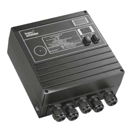
Burner control units BCU 480
Technical Information · GB
6 Edition 03.16l
• For pilot and main burners in intermittent or continuous operation
• Replace the local control cabinet
• Flame control by UV, ionization or a further option of using the
furnace chamber temperature
• Display of the program status, unit parameters and flame signal;
Manual mode for burner adjustment and for diagnostic purposes
Industrial & Commercial Thermal
AGA
Advertisement
Table of Contents

Related Manuals for Honeywell Krom Schroeder BCU 480


Summary of Contents for Honeywell Krom Schroeder BCU 480
-
Page 1: Burner Control Units Bcu 480
Industrial & Commercial Thermal Burner control units BCU 480 Technical Information · GB 6 Edition 03.16l • For pilot and main burners in intermittent or continuous operation • Replace the local control cabinet • Flame control by UV, ionization or a further option of using the furnace chamber temperature • Display of the program status, unit parameters and flame signal;... -
Page 2: Table Of Contents
Contents Burner control units BCU 480 . . . . . . . . . . . . . . . . . . . . . . . 1 4.1 Scanning the parameters. - Page 3 4.7.7 Air valve opens with operating signal ....52 6.16 Signal distributor board ......62 4.7.8 Low fire over-run time t after a controlled shut- 6.17 PROFIBUS DP .
- Page 4 9.4 Housing dimensions ......77 9.5 Operating controls....... . 77 9.6 Installation .
-
Page 5: Application
Application The BCU unites the function- ally interrelated components of automatic burner control unit, igni- tion transformer, Manual/Automatic mode and display of operating and fault statuses in a compact metal housing. 1 Application only relate to the burner, for example it ensures that the burner always ignites in a safe condition when it is The burner control units BCU 480 control, ignite and restarted. - Page 6 Application The service personnel is supported by a convenient vis- ualization system of the input and output signals and the error history. The new power management scheme reduces installa- tion and wiring costs. The power for the valves and igni- tion transformer is supplied via the power supply of the BCU, protected by a replaceable fine-wire fuse.
-
Page 7: Examples Of Application
Application 1 .1 Examples of application 1 .1 .1 Stage-controlled main burner with alternating pilot burner Control: L1, N, PE Main burner ON/OFF. The main burner can be started with reduced capacity after the operat- ing signal from the pilot burner has been detected. -
Page 8: Stage-Controlled Main Burner With Permanent
Application 1 .1 .2 Stage-controlled main burner with permanent pilot burner Control: Main burner ON/OFF. L1, N, PE The main burner can be started with reduced capacity after the operat- ing signal from the pilot burner has been detected. Pilot and main burn- ers can be operated simultaneously. -
Page 9: Two-Stage-Controlled Main Burner With
Application 1 .1 .3 Two-stage-controlled main burner with permanent pilot burner L1, N, PE Control: Main burner ON/OFF with ignition via bypass. The main burner can be started at low-fire rate after the operating sig- BCU 480 nal from the pilot burner has been detected. -
Page 10: Modulating-Controlled Burner
Application 1 .1 .4 Modulating-controlled burner Control: Main burner continuous. L1, N, PE The butterfly valve for air is moved to ignition position in order to start the main burner. The main burner can be started at low-fire rate after the operating signal from the pilot BCU 480 burner has been detected. -
Page 11: Bcu 480..D
Application 1 .1 .5 BCU 480 . .B1 for PROFIBUS DP The bus system transfers the control signals for starting, resetting and L1, N, PE for controlling the air valve from the control system to the BCU 480..B1. In the opposite direction, it sends op- erating status, the level of the flame PROFIBUS-DP signals and the current program... -
Page 12: Certification
Certification 2 Certification FM approved Certificates – see Docuthek. Certified to SIL and PL Factory Mutual Research Class: 7610 “Combustion Safeguards and Flame Sensing Systems”. Suitable for applications pursuant to NFPA 86. For systems up to SIL 3 pursuant to EN 61508 and PL www.approvalguide.com e pursuant to ISO 13849 AGA approved... -
Page 13: Function
Function BCU 480..E1 (BCU 480..C) Test 40 41 42 43 44 45 46 47 µC 9 10 12 13 14 15 16 17 18 19 20 25 26 27 28 29 30 31 32 33 34 35 36 37 50 51 max. -
Page 14: Bcu 480
Function BCU 480 (BCU 480..C) Test 40 41 42 43 44 45 46 47 µC 9 10 12 13 14 15 16 17 18 19 20 25 26 27 28 29 30 31 32 33 34 35 36 37 50 51 max. -
Page 15: Bcu 480
Function BCU 480..B1..E1 (BCU 480..C) Test 40 41 42 43 44 45 46 47 µC 9 10 12 13 14 15 18 19 20 25 26 27 30 31 32 33 34 35 36 37 50 51 max. 2 A, 253 V L1 (L1) N (L2) -
Page 16: Bcu 480
Function BCU 480..B1 (BCU 480..C) Test 40 41 42 43 44 45 46 47 µC 9 10 12 13 14 15 18 19 20 25 26 27 30 31 32 33 34 35 36 37 50 51 max. 2 A, 253 V L1 (L1) N (L2) -
Page 17: Bcu 460
Function BCU 480..P..E1 (BCU 480..P..C) 40 41 42 43 44 45 46 47 µC max. 2 A, 253 V 9 10 12 13 14 15 18 19 20 25 26 27 28 29 30 31 32 33 34 35 36 37 50 51 16 15 14 8 11 10... -
Page 18: Bcu 460
Function BCU 480..P (BCU 480..P..C) 40 41 42 43 44 45 46 47 µC max. 2 A, 253 V 9 10 12 13 14 15 18 19 20 25 26 27 28 29 30 31 32 33 34 35 36 37 50 51 16 15 14 8 11 10... -
Page 19: Bcu
Function 3 .2 BCU . .P with 16-pin industrial plug connector The burner control unit BCU 480..P can be supplied with an industrial plug connector (pursuant to VDE 0627). This 16-pin plug connector ensures fast con- necting or disconnecting of units without any addition- al wiring required. -
Page 20: Profibus Dp
Function 3 .3 PROFIBUS DP BCU..B1 features the same scope of functions and per- formance of a BCU ® without a PROFIBUS connection. PROFIBUS is a manufacturer-independent, open field- L1, N, PE bus standard for diverse applications. PROFIBUS DP is a bus variant for communication be- tween automation systems and distributed peripherals at the field level, optimized for speed and low connec- tion costs. -
Page 21: Bcsoft
Function 3 .3 .2 BCSoft ferred to as “slaves”. The Windows software BCSoft allows extended access This also includes the BCU..B1. to individual statistics, protocol functions, line record- 3 .3 .4 Addressing ers and the parameterization of the burner control unit A maximum of 126 units (masters and slaves) can be via an optical interface. -
Page 22: Network Technology
Function 3 .3 .5 Network technology 3 .3 . 7 Bus communication All devices are connected in a bus structure (line). Up Input bytes (BCU ➔ master) to 32 stations (masters or slaves) can be connected in Byte 0 Byte 1 Byte 2 Byte 3 Byte 4... - Page 23 Function I/O bytes: the programmer can choose the data to be transferred. Inputs Outputs 480 basic I/O 1 byte 1 byte 480 standard I/O 5 bytes 1 byte Baud rate: up to 1500 kbit/s. The max. range per segment depends on the baud rate: Baud rate [kbit/s] Range [m] 93.75...
-
Page 24: Bcu 480 Program Sequence
Function 3 .4 BCU 480 program sequence BCU 480 Switch on BCU 480 If the air valve control is used, Normal start-up the unit offers the following ad- In the event of fault signal: If an “old” fault is still being signalled after ditional functions: reset switching on, it will be necessary to reset this... - Page 25 or fault lock-out Function The BCU coordinates the correct pro- gram run for the pilot and main burn- Flame proving period t The air valve can be set to open running (P23) ers. The main burner can be started together with V1 (display via the signal input “Start-up signal via parameter 30.
- Page 26 max. 3 start-up attempts or fault lock-out Function Behaviour of the pilot burner in the event of flame failure during The air valve can be set to open Flame proving period operation running (P24) with V2 or to be activated ex- If the flame fails during operation, ternally (display ) via param-...
-
Page 27: Program Status And Fault Messages
Function 3 .5 Program status and fault messages Program status DISPLAY Fault message (flashing) BCU switched off – – Start-up position/Standby Purge Waiting time/Pause time Flame simulation Safety time on start-up, pilot burner Start-up without flame signal, pilot burner ... - Page 28 Function DISPLAY Program status Fault message (flashing) EEPROM data change, NFS* EEPROM data change, FS* Undervoltage in power pack Faulty parameterization Bus module fault Safety interlock failure Permanent remote reset Timing cycle too short ...
-
Page 29: Parameters
Parameters 4 Parameters Factory Description Parameter Value range Adjustable* default setting Flame signal, pilot burner 0 – 99 μA Flame signal, main burner 0 – 99 μA Program status when the most recent fault occurred x0 – x8 Switch-off threshold, pilot burner 1 – 20 µA 1 µA ... -
Page 30: Scanning The Parameters
Parameters Factory Description Parameter Value range Adjustable* default setting High temperature operation** 2; 3 Manual mode limited to 5 minutes 0; 1 UVS check (1 x in 24 hours) 0; 1 Low fire over-run time** 0; 5; 15; 25 s ... -
Page 31: Flame Control
Parameters 4 .2 Flame control 4 .2 .4 Switch-off threshold of the flame amplifier Parameter 04, pilot burner switch-off threshold 4 .2 .1 Flame signal, pilot burner Parameter 05, main burner switch-off threshold Parameter 01 The sensitivity at which the burner control unit still de- Flame signal of the pilot burner, display in μA, measur- tects a flame can be set between 1 and 20 μA. -
Page 32: High Temperature Operation In The Case Of Bcu
Parameters 4 .2 .5 High temperature operation in the case of ture. For this purpose, we recommend a safety temper- BCU . .D2 or BCU . .D3 ature monitor with double thermocouple (DIN 3440). Parameter 33 Sensor discontinuity, sensor short-circuit, failure of a component or mains failure must set the installation to Operation of firing systems at temperatures above a safe state. - Page 33 Parameters The BCU then responds, depending on setting: Parameter 33 = 3 (BCU..D3) Parameter 33 = 2 (BCU..D2) 2c–4c 16-17 6a–6e 2e–4e 28-29 18-19 The burner remains in operation and the BCU performs flame control again (recommended in the case of ioni- zation control or UV control with UVD).
- Page 34 Parameters If no flame signal is present when high temperature op- eration is deactivated, the burner control unit performs a fault lock-out, regardless of parameter 33. Fault, pilot burner 16-17 28-29 18-19 Fault, main burner 16-17 28-29 18-19 BCU 480 · Edition 03.16l...
-
Page 35: Uvs Check
Parameters 4 .2 .6 UVS check Parameter 35 An automatic restart of the burner control unit can be activated every 24 hours via this parameter. The time starts each time the start-up signal (ϑ) is applied. Parameter 35 = 0: Unlimited burner operation. Parameter 35 = 1: An automatic restart is activated once every 24 hours. -
Page 36: Pilot And Main Burner Monitoring
Parameters 4 .3 Pilot and main burner monitoring Intermittent pilot burner Automatic burner control unit BCU 480 for pilot and 02–04 06–08 02–04 06–08 main burner combination of unlimited capacity. Pilot burner: single-stage-controlled. Main burner: modulating or stage-controlled. Pilot and main burners are controlled with one start-up The burner control unit BCU 480 has separate start-up signal (terminals 4 and 21 in parallel). -
Page 37: Permanent Pilot Burner
Parameters 4 .3 .1 Permanent pilot burner 4 .3 .2 Interrupted pilot burner Parameter 16 = 1 Parameter 16 = 0 ϑ1 16-17 16-17 ϑ2 28-29 28-29 18-19 18-19 Operating mode: Permanent pilot burner Operating mode: Interrupted pilot burner In the “Permanent pilot burner” operating mode, the pi- If parameter 16 = 0, the pilot burner is switched off once lot burner remains in operation until its start-up signal the safety time t... -
Page 38: Behaviour In Start-Up Position/Standby
Parameters 4 .4 Behaviour in start-up position/standby fore start-up in order for the flame simulation check to be conducted correctly. 4 .4 .1 Flame simulation check in start-up position/ Flame simulation check depending on parameter 16, see standby page 37 (Permanent pilot burner) and (Interrupted pilot Parameter 15 burner): This defines the instant for the flame simulation check. -
Page 39: Minimum Burner Pause Time T Bp
Parameters 4 .4 .2 Minimum burner pause time t closed and, possibly, gas can be flared off, before a re- Parameter 21 start occurs. Programmable time between 0 and 250 s Example of application L1, N, PE 16-17 BCU 480 µC 28-29 18-19... -
Page 40: Behaviour During Start-Up
Parameters 4 .5 Behaviour during start-up Main burner Parameter 24 4 .5 .1 Safety time on start-up t Pilot burner Parameter 22 ϑ1 16-17 ϑ2 ϑ1 28-29 18-19 16-17 18-19 This indicates the safety time on start-up t for the main burner. -
Page 41: Flame Proving Period T
Parameters 4 .5 .2 Flame proving period t 4 .5 .3 Minimum burner on time t Parameter 20 Pilot burner Parameter 23 Programmable time in the range from minimum safety time on start-up t to maximum 25 s during which the main burner remains in operation. -
Page 42: Burner Start-Up Attempts
Parameters 4 .5 .4 Burner start-up attempts 2 or 3 start-up attempts Parameter 10 = 2, 3 Pilot burner Parameter 10 This indicates the number of possible start-up attempts of the burner. ϑ1 In accordance with EN 746-2, three start-ups are per- mitted in specific cases if the safety of the installation 16-17 18-19... - Page 43 Parameters Main burner 2 or 3 start-up attempts Parameter 11 Parameter 11 = 2, 3 This indicates the number of possible start-up attempts of the main burner. In accordance with EN 746-2, three start-ups are per- mitted in specific cases if the safety of the installation 16-17 is not impaired (note the requirements of the Stand- ards).
-
Page 44: Behaviour During Operation
Parameters 4 .6 Behaviour during operation 4 .6 .1 Safety time during operation t for pilot and main burners Parameter 14 This indicates the safety time during operation t 16-17 valves V1 and V2. 18-19 The default in accordance with EN 298 is 1 s. The BCU has also the available option of a safety time After a fault lock-out, the burner control unit can be during operation t... - Page 45 Parameters Restart in the event of flame failure Parameter 12 = 1: Restart in the event of flame failure. >2 s 16-17 18-19 If the BCU detects a flame failure after a minimum op- erating time of 2 s, the valves are closed and the opera- tion signalling contact is opened within time t The burner control unit now attempts to restart the burner once.
-
Page 46: Fault Lock-Out Or Restart, Main Burner
Parameters 4 .6 .3 Fault lock-out or restart, main burner After a fault lock-out, the burner control unit can be This parameter determines whether the BCU starts a reset, either with the button on the front panel or using one-off restart or performs an immediate fault lock-out an external button. -
Page 47: Program Status On Last Fault
Parameters Restart in the event of flame failure the program sequence started by the BCU matches the Parameter 13 = 1: Restart in the event of flame failure. application. 4 .6 .4 Program status on last fault Parameter 03 This indicates the program status in which the last burner fault occurred. -
Page 48: Air Valve Control On Bcu
Parameters 4 . 7 Air valve control on BCU . .L 4 . 7 .1 Purge In the case of multiple burner applications, burners with Parameter 30, Behaviour of the air valve during opera- mechanical combustion air supply are used. The air for tion. -
Page 49: (Not During Start-Up)
Parameters 4 . 7 .4 Air valve opens in the case of external Parameter 30 = 0: The air valve opens if it is activated activation (not during start-up) externally via input 23. Parameter 31 = 0: The air valve remains closed during 00 A000 start-up even if it is activated externally. -
Page 50: (Even During Start-Up)
Parameters 4 . 7 .5 Air valve opens in the case of external Parameter 30 = 0: The air valve opens if it is activated activation (even during start-up) externally via input 23. Parameter 31 = 1: The air valve can be activated even 00 A0 00 A0 during start-up. -
Page 51: Air Valve Opens With Valve V2
Parameters 4 . 7 .6 Air valve opens with valve V2 Parameter 30 = 2: The air valve opens simultaneously with valve V2. 00 A0 00 Application: single-stage-controlled main burner is switched ON/OFF via the ϑ input. The air valve can be activated externally via input 23 for 16-17 cooling the burner in the start-up position/standby. -
Page 52: Air Valve Opens With Operating Signal
Parameters 4 . 7 . 7 Air valve opens with operating signal Parameter 30 = 3: The air valve opens simultaneously with the operating signal. Application: two-stage-controlled main burner is switched ON/OFF via the ϑ input. The air valve can be activated externally via input 23 for 16-17 cooling the burner in the start-up position/standby. -
Page 53: Low Fire Over-Run Time T
Parameters 4 .7 .8 Low fire over-run time t after a controlled This parameter is applicable to systems with a pneu- shut-down matic air/gas ratio control system and On/Off control. Parameter 36 = 0 (low fire over-run time t = 0 s): Without low fire over-run, the gas circuit is closed im- mediately owing to the quick-closing gas valve in the case of On/Off control. -
Page 54: Behaviour Of The Air Valve In The Event Of A Fault
Parameters 4 . 7 .9 Behaviour of the air valve in the event of a fault lock-out Parameter 32 This determines whether the air valve can be activated in the event of a fault lock-out. Parameter 32 = 0: The air valve is closed in the event of a fault. -
Page 55: Manual Mode
Parameters 4 .8 Manual mode Manual mode can be terminated by switching off the BCU (On/Off button). For convenient setting of the burner or analyzing faults. 4 .8 .1 Manual mode limited to 5 minutes The parameter display is not available in Manual mode. Parameter 34 Manual mode can be accessed only if the unit was not in Fault state before switching off. -
Page 56: Selection
Selection 5 Selection T -3 -5 -10 /3 /5 /1 /2 L 5 15 25 W R 1 2 3 8 GB D2 D3 S2 S3 /2 /3 U C B1 /1 E1 Order example BCU 480 BCU 480-5/3/1LW3GBCE1 ... -
Page 57: Project Planning Information
Project planning information 6 Project planning information Avoid external electrical interference. The longer the ig- nition cable, the lower the ignition capacity. 6 .1 Cable selection Lay cable individually and, if possible, not in a metal Use mains cable suitable for the type of operation and conduit. -
Page 58: Calculating The Safety Time T Sa
Project planning information 6 .3 Calculating the safety time t BCU 480 · Edition 03.16l... -
Page 59: Minimum Burner On Time
Project planning information 6 .4 Minimum burner on time of the application, e.g. safety temperature limiter, mini- mum and maximum gas pressure, tightness control) Even if the start-up signal (ϑ) is applied only briefly, the must isolate terminal 5 from the voltage supply. If the time set under parameter 20 elapses. -
Page 60: Emergency Off
Project planning information 6 . 7 Emergency off button on the unit. The burner malfunction must be remedied. The mal- 6 . 7 .1 In the event of fire or electric shock function cannot be remedied by changing the method If there is a risk of fire, electric shock or similar, inputs of activation. -
Page 61: Fault Signalling
Project planning information 6 .11 Fault signalling 6 .13 Installation The fault signalling contact opens, as soon as the mains Recommended installation position: vertical (cable voltage fails. glands pointing downwards). When installing, ensure that there is sufficient space to 6 .12 Protecting the pilot burner from overload open the BCU. -
Page 62: Wiring
Project planning information 6 .14 Wiring Unit replacement A BCU without power management may not be re- Electrical connection via plug-in connection terminals placed with a BCU with power management (BCU..E1). (2.5 mm²) and plug-in cable glands. The latter can be The reverse also applies, i.e. -
Page 63: Profibus Dp
Project planning information 6 .17 PROFIBUS DP cable must be used. The shield must be connected to protective earth on both sides using wide-area shield 6 .17 .1 Safety-related control signals clips that ensure good conductivity. Signals from the safety interlocks and digital input are In addition, it must be ensured that all cables leading to transferred independently of the bus communication and from the BCU... -
Page 64: Status And Fault Messages For Profibus Dp
Project planning information 6 .17 .5 Status and fault messages for PROFIBUS DP This table can be used to program the master. Input bytes (BCU ➔ master) Status signal Fault signal Byte 2 Display Byte 0, Bit 2 = 0 Byte 0, Bit 2 = 1 Start-up position/standby Cooling... - Page 65 Project planning information Input bytes (BCU ➔ master) Status signal Fault signal Byte 2 Display Byte 0, Bit 2 = 0 Byte 0, Bit 2 = 1 Fuse F1 defective or safety interlocks discontinuity Permanent remote reset Timing cycle too short Internal error/negative flame current Display on BCU..L upon activation of the air valve during program step x ** FS = input/output, safety circuit, NFS = input/output, control system...
-
Page 66: Third Gas Valve (Can Be Shut Down) On Bcu
Project planning information 6 .18 Third gas valve (can be shut down) on BCU . .L Units with air valve control have an L1, N, PE additional contact (terminal), which closes at the same time as the air valve. This can be used to activate a third gas valve (V3). -
Page 67: Bcu Switched Off
Project planning information 6 .19 BCU switched off functionally from the central control system. This func- tion is required for manual operation and, in the case of In general, the BCU cannot be activated when no mains PROFIBUS units, to switch off the unit without causing voltage is applied or the burner control unit is switched bus errors. -
Page 68: Changing Parameters
Project planning information 6 .24 Changing parameters In certain cases, it may be necessary to change the default settings. Using a separate software package and a PC opto-adapter, it is possible to modify certain parameters on the BCU, such as the switch-off thresh- old of the flame amplifier, the behaviour in the event of a flame failure or whether the pilot burner is to burn permanently in the case of pilot and main burner moni-... -
Page 69: Flame Control
Flame control 7 Flame control Further information can be found in brochure UVS at www.docuthek.com. 7 .1 With ionization sensor The burner control unit BCU..U is prepared for UV sen- The BCU generates an alternating voltage (230 V AC) sor UVD 1. This enables continuous operation. between the sensing electrode and burner ground. -
Page 70: Via The Temperature In High Temperature
Flame control 7 .3 Via the temperature in high temperature equipment High temperature equipment is defined as a thermo- processing installation, in which the wall temperature of the combustion chamber and/or the processing cham- ber exceeds 750°C. Burner control units BCU..D feature a special “High temperature operation”... -
Page 71: Accessories
Accessories 8 Accessories 8 .3 PROFIBUS plug connector Variosub PROFIBUS plug connector, 9-pin, with deacti- 8 .1 High-voltage cable vatable bus terminator, Order No.: 74960431 FZLSi 1/7 up to 180°C, GSD files for BCU Profibus DP on BCSoft CD-ROM, Or- Order No.: 04250410. -
Page 72: Bcsoft
Accessories 8 .4 BCSoft 8 .5 “Changed parameters” stickers Affix on the connection dia- The current software can be downloaded from our In- D-49018 Osnabrück, Germany gram of the BCU following ternet site at http://www.docuthek.com. To do so, you changes to unit parameters set need to register in the DOCUTHEK. -
Page 73: External Securing Bar
Accessories 8 .6 External securing bar 8 . 7 Fastening set 22 mm 12 mm 7 mm ø 4mm Order No.: 74960414 Order No.: 74960422 8 .8 Radio interference suppressed electrode plugs Angle plug, 4 mm, interference-suppressed, Order No. 04115308. Straight plug, 4 mm, interference-suppressed, Order No. -
Page 74: Technical Data
Technical data 9 Technical data puts), but total current for valves and ignition transformer: Mains voltage: max. 2.5 A 230 V AC, -15/+10%, 50/60 Hz, Fail-safe inputs and outputs: 115 V AC, -15/+10%, 50/60 Hz, All the inputs and outputs marked “ ” (see connection for grounded and ungrounded mains. -
Page 75: Bcu
Technical data Fuses in unit: 9 .1 BCU . .B1 F1: 3.15 A, slow-acting, H, pursuant to IEC 127-2/5. External fuse: 12 A per zone. Fuse for protecting the safety-relevant ignition, valve 9 .2 PROFIBUS DP 1, valve 2 and air valve outputs (terminals 7, 12, 14 and 26): 5 A, slow-acting, not replaceable. -
Page 76: Safety-Specific Characteristic Values
Technical data 9 .3 Safety-specific characteristic values Relationship between the Performance Level (PL) and the Safety Integrity Level (SIL) In the case of ionization control, SIL 3 suitable for Safety Integrity Level Diagnostic coverage DC 92.7% – Type of subsystem Type B to EN 61508-2, 7.4.3.1.4 High demand mode pursuant to EN Mode of operation... -
Page 77: Housing Dimensions
Technical data 9 .4 Housing dimensions Die-cast aluminium housing with plug-in terminal blocks and plug-in M20 cable glands or (16-pin) indus- trial plug connector for input signals and optionally pre- assembled cables for output signals. 9 .5 Operating controls A: Optical interface. B: Labelling field for individual labelling of the system components. -
Page 78: Legend
Legend 10 Legend Minimum burner on time t up to max. 25 s Minimum burner pause time 0 – 250 s Display Low fire over-run time 0 s, 5 s, 15 s or 25 s Input/Output, safety circuit Blinking display Ready Safety interlocks (Limits) Start-up signal, pilot burner Start-up signal, main burner Digital input... -
Page 79: Glossary
Glossary 11 Glossary ignition time is either 2, 3 or 7 seconds depending on safety time t selected. 11 .1 Waiting time t 11 .4 Flame simulation/Flame simulation delay time t 22-23 24-25 22-23 t SA 24-25 t LV Once the start-up signal ϑ has been applied, the wait- ing time t starts to elapse. -
Page 80: Safety Time During Operation T Sb
Glossary 11 .5 Safety time during operation t 11 .8 Safety interlocks (Limits) The limiters in the safety interlock (linking of all the rel- evant safety control and switching equipment for the use of the application, e.g. safety temperature limiter, minimum/maximum gas pressure) must isolate input from the voltage supply. -
Page 81: Main Gas Valve V2
Glossary 11 .10 Main gas valve V2 11 .13 Diagnostic coverage DC The start fuel flow rate for the main burner is released Measure of the effectiveness of diagnostics, which may by main gas valve V2. It opens when the safety time on be determined as the ratio between the failure rate of BCU 480 (BCU 480..C) -
Page 82: Probability Of Dangerous Failure Pfhd
Glossary 11 .16 Probability of dangerous failure PFH Value describing the likelihood of dangerous failure per hour of a component for high demand mode or con- tinuous mode. Unit: 1/h. from EN 13611/A2:2011 11 .17 Mean time to dangerous failure MTTF Expectation of the mean time to dangerous failure from EN ISO 13849-1:2008... -
Page 83: Feedback
Feedback Feedback Finally, we are offering you the opportunity to assess this “Technical Information (TI)” and to give us your opinion, so that we can improve our documents further and suit them to your needs. Clarity Comprehension Scope Found information quickly Coherent Too little Too complicated...