Table of Contents
Advertisement
Quick Links
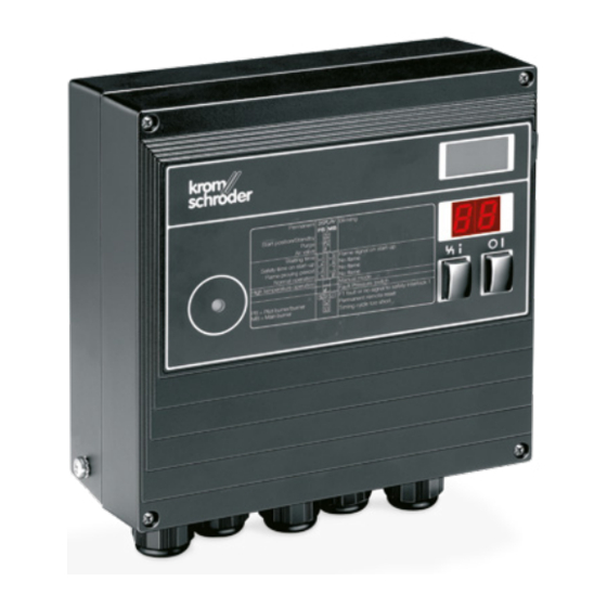
Burner control unit BCU 440
Technical Information · GB
6 Edition 01.17
• Automatic burner control unit, ignition transformer, indicators and
operating controls in a space-saving metal housing which
replaces the local burner control cabinet
• For directly ignited burners of up to 350 kW in continuous
operation pursuant to EN 746-2
• Display of the program status, unit parameters and flame signal;
Manual mode for burner adjustment and for diagnostic purposes
• Visualisation and adaptation to the specific application via the PC
programming and diagnostic software BCSoft to simplify logistics
management.
AGA
Advertisement
Table of Contents

Related Manuals for Honeywell krom schroder BCU 440


Summary of Contents for Honeywell krom schroder BCU 440
-
Page 1: Burner Control Unit Bcu 440
Burner control unit BCU 440 Technical Information · GB 6 Edition 01.17 • Automatic burner control unit, ignition transformer, indicators and operating controls in a space-saving metal housing which replaces the local burner control cabinet • For directly ignited burners of up to 350 kW in continuous operation pursuant to EN 746-2 •... -
Page 2: Table Of Contents
Contents Burner control unit BCU 440 . . . . . . . . . . . . . . . . . . . . . . . . 1 6.3 Calculating the safety time t . - Page 3 9 Technical data . . . . . . . . . . . . . . . . . . . . . . . . . . . . . . . . . . . 29 9.1 Safety-specific characteristic values .
-
Page 4: Application
Application The BCU unites the functionally interrelated com- ponents of auto- matic burner con- trol unit, ignition transformer, Man- ual/Automatic mode and display of operating and fault statuses in a compact metal housing. 1 Application The service personnel is supported by a convenient vis- ualisation system of the input and output signals and Burner control unit BCU 440 controls, ignites and mon- the error history. - Page 5 Application Roller hearth kiln in the Chamber kiln Roller hearth kiln ceramics industry BCU 440 · Edition 01.17...
-
Page 6: Examples Of Application
Application 1 .1 Examples of application 1 .1 .1 Atmospheric burners Control: ON/OFF The burner is ignited by the spark electrode and is mon- itored by the flame rod. In the event of a flame failure L1, N, PE during start-up, an immediate fault lock-out occurs. In the event of a flame failure during operation, an imme- diate fault lock-out or a restart occurs, depending on the unit parameter settings. -
Page 7: Bcu 440: Modulating-Controlled Burner
Application 1 .1 .2 BCU 440: Modulating-controlled burner L1, N, PE Control: continuous. Modulating control of the gas flow rate with a constant air flow rate. The burners start at low-fire rate, and the actuator IC 20 controls the burner capacity via the lin- ear flow control LFC after the operating state has been BCU 440 signalled. -
Page 8: Certification
Certification 2 Certification FM approved Certificates – see Docuthek. Certified pursuant to SIL Factory Mutual Research Class: 7610 “Combustion Safeguards and Flame Sensing Systems”. Suitable for applications pursuant to NFPA 86. For systems up to SIL 3 pursuant to EN 61508. www.approvalguide.com Pursuant to EN ISO 13849-1:2006, the BCU can be AGA approved... -
Page 9: Function
Function BCU 440 1 2 3 7 8 9 12 13 16 17 18 19 20 max. 2 A, max. 2 A, 253 V 253 V ϑ L1 (L1) N (L2) 7 8 9 3 Function 3 .1 Connection diagram For cable selection and wiring, see page 19 (Project planning information). -
Page 10: Zonal Series Wiring
Function 3 .1 .1 Zonal series wiring BCU 440 For cable selection and wiring, see (L1) (L1) page 19 (Project planning infor- max. 2 A, mation). max. 2 A, 253 V 253 V ϑ For the explanation of symbols, see 1 2 3 7 8 9 12 13... -
Page 11: Program Sequence
Function 3 .2 Program sequence Normal start-up If an “old” fault is still being signalled after switching on, it will be necessary to reset this first. When the safety interlocks are closed, the burner can be started with the start-up signal (ϑ). The flame simulation check is conducted during the waiting time, once mains voltage has been applied. -
Page 12: Program Status And Fault Messages
Function 3 .3 Program status and fault messages During operation, the 7-segment display shows the pro- gram status. In the event of a fault, the BCU halts the program run, the display blinks and it then displays the cause of the fault. The burner control unit can be reset using the Reset button or the remote reset. -
Page 13: Parameters
Parameters 4 Parameters Description Parameter Value range Factory default setting Adjustable* Burner flame signal 0 – 99 µA Program status when the most recent fault occurred x0 – x8 Switch-off threshold of the flame amplifier 1 – 20 µA 1 µA Fault lock-out or restart 0;... -
Page 14: Flame Control
Parameters 4 .2 Flame control 4 .3 Behaviour during start-up 4 .2 .1 Burner flame signal 4 .3 .1 Safety time on start-up t Parameter 01 Parameter 22 Flame signal of the burner, display in µA, measuring range: 0 – 30 µA. ϑ... -
Page 15: Behaviour During Operation
Parameters 4 .4 Behaviour during operation 4 .4 .2 Fault lock-out or restart Parameter 12 4 .4 .1 Safety time during operation t This parameter determines whether the BCU starts a Parameter 14 one-off restart or performs an immediate fault lock-out This indicates the safety time during operation t for the burner after an installation fault (flame failure or valve V1. - Page 16 Parameters Immediate fault lock-out after installation fault Restart following flame failure Parameter 12 = 0: Fault lock-out after installation fault. Parameter 12 = 1: Restart after installation fault. ϑ ϑ > 2 s 16-17 18-19 16-17 18-19 If the BCU detects an installation fault (flame failure) after a minimum operating time of 2 s, the valves are After an installation fault (flame failure), the burner con- closed and the operation signalling contact is opened...
-
Page 17: Program Status When The Most Recent Fault
Parameters 4 .4 .3 Program status when the most recent fault occurred Parameter 03 This indicates the program status in which the last burner fault occurred. Example: The unit indicates that fuse F1 is defective with a blinking 50 . Parameter 03 can now be used to scan in what program status the BCU was when the fault was detected. -
Page 18: Selection
Selection 5 Selection 5 .1 Selection table -3 -5 -10 /1 /2 4 GB BCU 440 = standard, = available Order example BCU 440-3/1W1GB 5 .1 .1 Type code Code Description Burner control unit... -
Page 19: Project Planning Information
Project planning information 6 Project planning information Lay cable individually and, if possible, not in a metal conduit. 6 .1 Cable selection Do not lay UV/ionization cable and ignition cable to- Use mains cable suitable for the type of operation and gether and lay them as far apart as possible. -
Page 20: Calculating The Safety Time T Sa
Project planning information 6 .3 Calculating the safety time t BCU 440 · Edition 01.17... -
Page 21: Safety Interlocks (Limits)
Project planning information 6 .4 Safety interlocks (Limits) 6 .5 Protection of safety-relevant outputs The limiters in the safety interlock (linking of all the rel- When commissioning, do not switch the safety-relevant evant safety control and switching equipment for the outputs to a short-circuit. -
Page 22: Reset
Project planning information 6 .6 Reset 6 .6 .4 Burner start A furnace start may only be initiated, if it has been 6 .6 .1 Parallel reset ensured using an appropriate procedure that there is Several burner control units can be reset in parallel us- no combustible mixture in the burner tile/processing ing the external button. -
Page 23: Emergency Stop
Project planning information 6 . 7 Emergency stop 6 .10 Installation Recommended installation position: vertical (cable 6 . 7 .1 In the event of fire or electric shock glands pointing downwards). If there is a risk of fire, electric shock or similar, inputs L1 and N of the BCU should be disconnected from the When installing, ensure that there is sufficient space to electrical power supply –... -
Page 24: Wiring
Project planning information 6 .11 Wiring 6 .14 Mains switch Electrical connection via plug-in connection terminals The mains switch in the unit isolates the BCU on two (2.5 mm²) and plug-in cable glands. The latter can be poles from the mains. It does not meet the require- removed in order to facilitate installation. -
Page 25: Changing Parameters
Project planning information 6 .16 Changing parameters In certain cases, it may be necessary to change the de- fault settings. Using a separate software package and a PC opto-adapter, it is possible to modify certain pa- rameters on the BCU, such as the switch-off threshold of the flame amplifier or the behaviour in the event of a flame failure. -
Page 26: Flame Control
Flame control 7 Flame control With ionisation sensor The BCU generates an alternating voltage (230 V AC) between the sensing electrode and burner ground. The flame rectifies this voltage. Only the DC signal (> 1 µA) is detected by the burner control unit. A flame cannot be simulated. -
Page 27: Accessories
Accessories 8 Accessories 8 .4 BCSoft The current software can be downloaded from our In- 8 .1 High-voltage cable ternet site at www.docuthek.com. To do so, you need to FZLSi 1/7 up to 180°C, register in the DOCUTHEK. Order No. 04250410. 8 .4 .1 Opto-adapter PCO 200 FZLK 1/7 up to 80°C, Order No. -
Page 28: External Securing Bar
Accessories 8 .5 External securing bar 8 .6 Fastening set 22 mm 12 mm 7 mm ø 4mm Order No. 74960414 Order No. 74960422 BCU 440 · Edition 01.17... -
Page 29: Technical Data
Technical data 9 Technical data Power consumption: approx. 9 VA plus inherent con- sumption of the integrated ignition transformer Mains voltage: (50/60 Hz). 230 V AC. -15/+10%. 50/60 Hz. Inherent consumption of ignition transformer: 115 V AC. -15/+10%. 50/60 Hz. for grounded and ungrounded mains. - Page 30 Technical data Flame control: sensor voltage approx. 230 V AC, sensor current > 1 µA. Length of sensor cable: max. 5 m (16.4 ft). Fuses in unit: F1: 3.15 A, slow-acting, H, pursuant to IEC 127-2/5, Fuse for protecting the safety-relevant ignition and valve 1 outputs (terminals 7 and 12): Ambient temperature: -20 to +60°C (-4 to +140°F), climate: no condensation permitted.
-
Page 31: Safety-Specific Characteristic Values
Technical data 9 .1 Safety-specific characteristic values Relationship between the Performance Level (PL) and the Safety Integrity Level (SIL) In the case of ionization control, SIL 3 suitable for Safety Integrity Level Diagnostic coverage DC 92.7% – Type of subsystem Type B to EN 61508-2, 7.4.3.1.4 High demand mode pursuant to Operating mode... -
Page 32: Housing Dimensions
Technical data 9 .2 Housing dimensions Die-cast aluminium housing with plug-in terminal blocks and plug-in M20 cable glands or (16-pin) plug connector for input signals and optionally pre-assem- bled cables for output signals. 9 .3 Operating controls A: Optical interface. B: Labelling field for individual labelling of the system components. -
Page 33: Legend
Legend 10 Legend Display Blinking display Ready Safety interlocks (Limits) Burner start-up signal Ignition transformer Gas valve Air valve Purge Ext. air valve control Flame signal Burner operating signal Fault signal Reset Input signal Output signal Flame simulation check Waiting time ≥ 2 s Safety time on start-up 3 s, 5 s or 10 s Safety time during operation <... -
Page 34: Glossary
Glossary 11 Glossary 11 .3 Ignition time t If no malfunction is detected during the waiting time 11 .1 Waiting time t , the ignition time t then starts to elapse. Voltage is supplied to the pilot gas valve V1 and the ignition trans- former and the burner is ignited. -
Page 35: Safety Time During Operation T Sb
Glossary 11 .5 Safety time during operation t 11 .8 Safety interlocks (Limits) The limiters in the safety interlock (linking of all the rel- evant safety control and switching equipment for the use of the application, e.g. safety temperature limiter, ϑ... -
Page 36: Diagnostic Coverage Dc
Glossary 11 .13 Safe failure fraction SFF 11 .11 Diagnostic coverage DC Measure of the effectiveness of diagnostics, which may Fraction of safe failures related to all failures, which are be determined as the ratio between the failure rate of assumed to appear detected dangerous failures and the failure rate of total from EN 13611/A2:2011...