
Related Manuals for GE Versana Essential


Summary of Contents for GE Versana Essential
- Page 1 Technical Publication 5759238-100 English Rev. 2 Versana Essential User Guide R1.x.x Operating Documentation Copyright 2017 By General Electric Co.
- Page 2 Directive 93/42/EEC concerning medical devices. First CE Marked in 2017. This manual is a reference for the Versana Essential ultrasound system. It applies to all revisions of the R1.x.x software for the Versana Essential ultrasound system. P.O. Box 414, Milwaukee, Wisconsin 53201 U.S.A.
- Page 3 MyWorkshop/ePDM (GE Electronic Product Data Management). If you need to know the latest revision, contact your distributor, local GE Sales Representative or in the USA call the GE Ultrasound Clinical Answer Center at 1 800 682 5327 or 1 262 524 5698.
- Page 4 This page intentionally left blank. – Versana Essential User Guide 5759238-100 English Rev. 2...
- Page 5 The location of the CE marking is shown in the Safety chapter of this manual. Authorized EU Representative European registered place of business: GE Medical Systems SCS 283 rue de la Minière 78530 BUC, France – Versana Essential User Guide...
- Page 6 General Requirements for Safety. • NEMA/AIUM Acoustic Output Display Standard (NEMA UD3). • Medical Device Good Manufacturing Practice Manual issued by the FDA (Food and Drug Administration, Department of Health, USA). – Versana Essential User Guide 5759238-100 English Rev. 2...
-
Page 7: Certifications
Conformance Standards (continued) Certifications • General Electric Medical Systems is ISO 9001 and ISO 13485 certified. Original Documentation • The original document was written in English. Importer Information • Turkey – Versana Essential User Guide 5759238-100 English Rev. 2... - Page 8 – Versana Essential User Guide 5759238-100 English Rev. 2...
-
Page 9: Table Of Contents
Patient Screen - - - - - - - - - - - - - - - - - - - - - - - - - - - - - - - - - - - - - - - - 1-44 – Versana Essential User Guide... - Page 10 Inspecting the System - - - - - - - - - - - - - - - - - - - - - - - - - - - - - - - - - - - 3-30 – Versana Essential User Guide...
- Page 11 Contact Information Contacting GE Ultrasound - - - - - - - - - - - - - - - - - - - - - - - - - - - - - - - - 3-62 Manufacturer - - - - - - - - - - - - - - - - - - - - - - - - - - - - - - - - - - - - - - - - - 3-68 Chapter 4 —...
- Page 12 Post Biopsy - - - - - - - - - - - - - - - - - - - - - - - - - - - - - - - - - - - - - - - - - - 5-42 Surgery/Intra-operative Use Preparing for Surgery/Intra-operative Procedures - - - - - - - - - - - - - - - 5-43 Index i-10 – Versana Essential User Guide 5759238-100 English Rev. 2...
-
Page 13: Chapter 1 - Getting Started
Chapter 1 Getting Started Console Overview, Moving the System, System Start-up, Probes and Beginning an Exam – Versana Essential User Guide 5759238-100 English Rev. 2... -
Page 14: Overview
NOTE: “Whiz“ is equal to “Whizz“ in all user manuals, service manuals and user interface for Versana Essential system. Safety instructions must be reviewed before operating the unit. CAUTION –... - Page 15 Overview Attention (continued) The Versana Essential manuals are written for users who are familiar with basic ultrasound principles and techniques. They do not include sonographic training or detailed clinical procedures. NOTE: The system color varies. NOTE: The electronic documentation CD includes English and all translations.
-
Page 16: Principles Of Operation
Sophisticated design with computer control offers a system with extensive features and functions which is user-friendly and easy to use. – Versana Essential User Guide 5759238-100 English Rev. 2... -
Page 17: Contraindication
Prescription Device CAUTION: United States law restricts this device to sale or use by, or on the order of a physician. Intended Use The Versana Essential is intended for use by a qualified physician for ultrasound evaluation. – Versana Essential User Guide 5759238-100 English Rev. -
Page 18: Indications For Use
Getting Started Indications for Use The Versana Essential are general purposed ultrasound imaging and analysis systems providing digital acquisition, processing and display capability and clinical applications including: Abdominal, Obstetrical, Gynecological, Small parts, Vascular/Peripheral Vascular, Adult Cephalic, Pediatric, Musculoskeletal, Transcranial, Neonatal Cephalic, Transvaginal, Urological and Cardiac, Transrectal, imaging guidance of interventional procedure and biopsy. - Page 19 Biopsy Image Acquisition is for diagnostic purposes including measurements on acquired image. This machine should be used in compliance with law. Some CAUTION jurisdictions restrict certain uses, such as gender determination. – Versana Essential User Guide 5759238-100 English Rev. 2...
-
Page 20: Site Requirements
Distributor Field Engineers and Application Specialists will install and setup the system. See ‘Contact Information’ on page 3-62 for more information. The Versana Essential does not contain any operator serviceable internal components. Ensure that unauthorized personnel do not tamper with the unit. - Page 21 Do not operate the system in the vicinity of a heat source, of CAUTION strong electric or magnetic fields (close to a transformer), or near instruments generating high-frequency signals, such as HF surgery. These can affect the ultrasound images adversely. – Versana Essential User Guide 5759238-100 English Rev. 2...
- Page 22 700 - 1060hPa 700 - 1060hPa The system cannot be used in OXYGEN rich environment. CAUTION Ensure that the probe face temperature does not exceed the CAUTION normal operation temperature range. 1-10 – Versana Essential User Guide 5759238-100 English Rev. 2...
- Page 23 Operating Environment Ensure that there is sufficient air flow around the ultrasound unit when installed in a fixed location. Do not cover the ventilation holes of the Versana Essential. CAUTION The Versana Essential system and probe connector are not CAUTION waterproof.
-
Page 24: Console Graphics
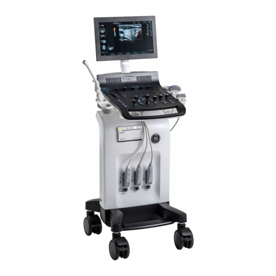
Getting Started Console graphics The following are illustrations of the console: Figure 1-1. Versana Essential System - an example 1. Monitor 7. Probe Holder 2. Speaker 8. Printer Box 3. Control Panel 9. Rear Panel 4. Probe Connector 10. Rear Handle 5. -
Page 25: Peripheral/Accessory Connection
Overview Peripheral/Accessory Connection Peripheral/Accessory Connector Panel Versana Essential peripherals and accessories can be properly connected using the rear connector panel. For compatibility reasons, use only GE approved probes, CAUTION peripherals or accessories. DO NOT connect any probes, peripherals or accessories without approval by GE. - Page 26 USB for use Composite Out Composited Video Out AC Inlet 100-240V Circuit breaker Circuit breaker Diagnostic LED 1 For diagnostic Diagnostic LED 2 For diagnostic Diagnostic LED 3 For diagnostic 1-14 – Versana Essential User Guide 5759238-100 English Rev. 2...
-
Page 27: Wired Footswitch (Option)
When using the Footswitch, DO NOT hold down the footswitch CAUTION pedal. Press and release the Footswitch pedal. Pushing and holding down the pedal behaves the same way as pushing and holding down a key on the keyboard. – 1-15 Versana Essential User Guide 5759238-100 English Rev. 2... -
Page 28: Control Panel Map
32. Comment key 21. Print key 11. M Mode/M Mode Gain 33. Utility 22. Freeze key NOTE: The factory default settings can be modified in Utility ->System -> User Configurable Key. 1-16 – Versana Essential User Guide 5759238-100 English Rev. 2... - Page 29 Overview Alphanumeric Keyboard Figure 1-6. Alphanumeric Keyboard – 1-17 Versana Essential User Guide 5759238-100 English Rev. 2...
- Page 30 Alt+D Collect the logs. Once the logs are collected, the engineering team would be able to see the marker you added which will help engineering to troubleshoot the problem. 1-18 – Versana Essential User Guide 5759238-100 English Rev. 2...
-
Page 31: Top/Sub Menu
Up/Down key to move to the next/previous page. Figure 1-8. Primary Menu NOTE: To perform functions on the primary menu when Whizz is on, only three functions on the primary menu are available for selection. – 1-19 Versana Essential User Guide 5759238-100 English Rev. 2... -
Page 32: Monitor Display
25. Focal Zone Indicator. 12. Trackball Functionality Status. 26. Body Pattern. 13. Current date and time, Caps Lock: (lit when on), 27. TGC. network connection indicator, system messages display, InSite status, InSite controls. 1-20 – Versana Essential User Guide 5759238-100 English Rev. 2... -
Page 33: To Adjust The Monitor Position
To avoid injury or damage, make sure nothing is within the CAUTION range of motion before moving the monitor. This includes both objects and people. – 1-21 Versana Essential User Guide 5759238-100 English Rev. 2... -
Page 34: Adjust Monitor By Software
Move the adjustment button to the left to decrease the contrast or move the adjustment button to the right to increase the contrast. Figure 1-13. Contrast 1-22 – Versana Essential User Guide 5759238-100 English Rev. 2... - Page 35 3. Press Reset to return to the default setting; Press Exit to exit the setting menu. NOTE: Press Reset button and the three color temperature settings will return to the default settings. – 1-23 Versana Essential User Guide 5759238-100 English Rev. 2...
-
Page 36: Moving The System
This equipment is not to be used during transportation (e.g. CAUTION ambulance cars, aircraft). Handle carefully. A drop of more than 5 cm can cause CAUTION mechanical damages. 1-24 – Versana Essential User Guide 5759238-100 English Rev. 2... - Page 37 8. Store sufficient gel and other essential accessories in the provided space. 9. Flip down the monitor. 10. Disconnect the footswitch from the console. 11. Unlock the wheels. – 1-25 Versana Essential User Guide 5759238-100 English Rev. 2...
-
Page 38: Wheels
1. Locked: Press on the brakes to block the caster wheels. 2. Unlocked: Release the brakes to unlock the caster wheels. Never move the system with locked wheels. Moving Hazard 1-26 – Versana Essential User Guide 5759238-100 English Rev. 2... -
Page 39: Moving The System
If you use/park the system on a slippery slope, you MUST use CAUTION the brakes on the wheel. – 1-27 Versana Essential User Guide 5759238-100 English Rev. 2... - Page 40 • Be sure the pathway is clear. • Limit movement to a slow careful walk. • Use two or more persons to move the system on inclines or long distances. 1-28 – Versana Essential User Guide 5759238-100 English Rev. 2...
- Page 41 DO NOT attempt to move the system with the monitor by CAUTION pulling cables or belts placed around the monitor and/or monitor arm. Do not put your whole body weight on the foot-rest holder. – 1-29 Versana Essential User Guide 5759238-100 English Rev. 2...
-
Page 42: Transporting The System
2. Ensure that the system is firmly secured while inside the vehicle. 3. Secure the system with straps or as directed otherwise to prevent motion during transport. Remove all peripherals from the console before transportation. CAUTION 1-30 – Versana Essential User Guide 5759238-100 English Rev. 2... - Page 43 Do not lay the unit down on its side. 9. Ensure that the system is firmly secured inside the vehicle. NOTE: DO NOT restrain the Versana Essential at the monitor or the monitor neck using a belt. 10. Prevent vibration damage by driving cautiously. Avoid unpaved roads, excessive speeds, and erratic stops or starts.
-
Page 44: System Start-Up
Do not use an extension cord or adapter plug. 6. Switch ON the Circuit Breaker (b).The On/Off button on the control panel illuminates blue, indicating that the system is in standby mode. 1-32 – Versana Essential User Guide 5759238-100 English Rev. 2... - Page 45 Only connect Versana Essential and mains-operated CAUTION accessories to the appropriate wall outlet. DO NOT connect them to a single or multiple socket outlets, an extension cord, power strip or an adapter plug.
- Page 46 NOT have other equipment operating on the same circuit. Disconnect the plug from the wall outlet in case an emergency CAUTION should occur. Ensure easy access to the power outlet. 1-34 – Versana Essential User Guide 5759238-100 English Rev. 2...
- Page 47 If the Circuit Breaker switch does not remain in the On position or trips again: 1. Disconnect the Power Cable. 2. Call Service immediately. DO NOT attempt to use the system. – 1-35 Versana Essential User Guide 5759238-100 English Rev. 2...
-
Page 48: Power On
Power On/Off switch illumination turns to blue. After a successful boot-up process, the Power On/Off switch illumination turns from blue to green, the keyboard backlight is lit. 1-36 – Versana Essential User Guide 5759238-100 English Rev. 2... - Page 49 System Start-Up Login Personal IDs and associated passwords can be preset on the Versana Essential. If the User Auto Logon preset is blank, you are prompted to login. Figure 1-20. Operator Login Window 1. Operator: Select the Operator. 2. Password: Enter Operator’s password (optional).
-
Page 50: Power Off
Data may be lost or system software damaged if the circuit breaker is turned off before the system shuts down. 4. Disconnect the power plug from the power outlet. 1-38 – Versana Essential User Guide 5759238-100 English Rev. 2... -
Page 51: Crash Recovery Instructions
Generic reports are not saved if the system crashes before you save it. The system crash may cause the internal HDD corruption. WARNING Avoid using the internal HDD as a permanent storage device. Backup data on a regular basis. – 1-39 Versana Essential User Guide 5759238-100 English Rev. 2... -
Page 52: Probes
Fault conditions can result in electric shock hazard. Do not CAUTION touch the surface of probe connectors which are exposed when the probe is removed. DO NOT touch the patient when connecting or disconnecting a probe. 1-40 – Versana Essential User Guide 5759238-100 English Rev. 2... - Page 53 4. Hold the probe connector horizontally with the cable pointing upward. 5. Slide the connector lock to the left (unlocked position). Figure 1-21. Unlocked position – 1-41 Versana Essential User Guide 5759238-100 English Rev. 2...
- Page 54 7. Wrap the probe cables around the probe cable hooks under the control panel. Ensure the probe cables are wrapped properly, not extended beyond sides of console. Figure 1-23. Handle probe cable 1-42 – Versana Essential User Guide 5759238-100 English Rev. 2...
-
Page 55: Cable Handling
3. Pull the probe connector straight out of the probe port carefully. 4. Ensure the cable is free. 5. Be sure that the probe head is clean before placing the probe in its storage box. – 1-43 Versana Essential User Guide 5759238-100 English Rev. 2... -
Page 56: Beginning An Exam
Figure 1-24. Patient Screen 1. Image Management 2. Function Selection 3. EZBackup/EZMove 4. Dataflow Selection 5. Scan 6. Patient Information 7. Category Selection 8. Exam Information 9. Patient View/Exam View 1-44 – Versana Essential User Guide 5759238-100 English Rev. 2... -
Page 57: Scanning A New Patient
In most cases, the operator sits/stands straight in front of the operator console and the patient lies on the bed on the right (or left) side of the system. – 1-45 Versana Essential User Guide 5759238-100 English Rev. 2... - Page 58 " ‘ / : ; . , * < > | + = [ ] & !, @, #, $, %, ^, &, *, (, ), ?, /, ~ , [, ], {, } 6. Select Register. Enter Past OB Exam information, if desired. 7. Select the probe to start scanning (or select Esc, Scan, or Freeze). 8. Perform the exam. 1-46 – Versana Essential User Guide 5759238-100 English Rev. 2...
- Page 59 Permanent Store to store the images permanently. After completing the measurement, verify that the CAUTION measurement result window is updated before you send or save the image. – 1-47 Versana Essential User Guide 5759238-100 English Rev. 2...
-
Page 60: Entering A Patient List
1. Select Patient on the control panel. 2. Select the patient from the Patient List. 3. Select New Exam. 4. A new exam is created. Enter the data and begin the scan. 1-48 – Versana Essential User Guide 5759238-100 English Rev. 2... -
Page 61: Scanning Without Entering Any Patient Data
6. Return to patient page, select New Patient. Ending a Patient To end a patient: Press Patient -> New Patient, then select Store All in the pop-up menus to store exam data. – 1-49 Versana Essential User Guide 5759238-100 English Rev. 2... -
Page 62: Changing Current Patient To Existing Patient (With Patient Id)
Select OK to delete the unsave images, select Cancel not to delete the images. 4. Cancel. Do nothing with the unsaved data, and return to Patient page. 1-50 – Versana Essential User Guide 5759238-100 English Rev. 2... -
Page 63: Changing Current Patient To Existing Patient (Without Patient Id)
Select OK to save the images. • Auto Generate The system will generate a new patient ID and the unsaved images will be saved to this new patient automatically. – 1-51 Versana Essential User Guide 5759238-100 English Rev. 2... - Page 64 ?” Select OK to delete the unsave all temporary images iamges, select Cancel not to delete the images. 4. Cancel. Do nothing with the unsaved data, and return to Patient page. 1-52 – Versana Essential User Guide 5759238-100 English Rev. 2...
-
Page 65: Delete The Existing Patient/Exam/Image
2. Select Exam View to display patient exam screen. 3. Select the exam to be deleted. 4. Select Delete Exam. The confirmation dialog box displays. 5. Select OK to delete or Cancel. – 1-53 Versana Essential User Guide 5759238-100 English Rev. 2... - Page 66 4. Select Active Images to display the image list. 5. Select the image to delete and select Delete. The confirmation dialog box displays. 6. Select Yes to delete or No to cancel. 1-54 – Versana Essential User Guide 5759238-100 English Rev. 2...
-
Page 67: Chapter 2 - Performing An Exam
Chapter 2 Performing an Exam Optimizing the Image, Measurement and Analysis – Versana Essential User Guide 5759238-100 English Rev. 2... -
Page 68: Optimizing The Image
Harmonic imaging utilizes Digitally Encoded Ultrasound (DEU). Imaging (Phase Coded Harmonics enhances near field resolution for improved Inversion Harmonic) small parts imaging as well as far field penetration. (CHI) Frequency Switch the frequency. – Versana Essential User Guide 5759238-100 English Rev. 2... - Page 69 The colorize bar displays while Colorize is activated. Edge Enhance Edge Enhance brings out subtle tissue differences and boundaries by enhancing the gray scale differences corresponding to the edges of structures. – Versana Essential User Guide 5759238-100 English Rev. 2...
- Page 70 The quality of the resulting image is somewhat user-dependent and requires some additional skill and practice to develop proper technique and become fully proficient. LOGIQ View is only available in B mode. – Versana Essential User Guide 5759238-100 English Rev. 2...
-
Page 71: M-Mode Controls
Available in M-Mode, Doppler Mode and M Color Flow Mode. Anatomical M-Mode Anatomical M-Mode gives you the ability to manipulate the cursor (option) at different angles and positions. The M-Mode display changes according to a motion of the M cursor. – Versana Essential User Guide 5759238-100 English Rev. 2... -
Page 72: Color Flow Mode Controls
Limits color flow overlay to low level echoes inside vessel walls. Helps minimize color `bleeding' outside vessel walls. Frame Average Averages color frames. Transparency Map Brings out the tissue behind the color map. – Versana Essential User Guide 5759238-100 English Rev. 2... - Page 73 QAnalysis (Option) QAnalysis is available for the image loop acquired in the following modes: TVI, CF and PDI. All of the QAnalysis modes operate similarly, with some variation. – Versana Essential User Guide 5759238-100 English Rev. 2...
-
Page 74: M Color Flow Mode
M-Mode image using velocity and variance color maps. The Color Flow wedge overlays the B-Mode image and M-Mode time line. See ‘Color Flow Mode Controls’ on page 2-6 for more information. – Versana Essential User Guide 5759238-100 English Rev. 2... -
Page 75: Doppler Mode Controls
The angle steer function only applies to linear probes. Volume Controls audio output. Invert Vertically inverts the spectral trace without affecting the baseline position. – Versana Essential User Guide 5759238-100 English Rev. 2... - Page 76 Gather samples along (option) the entire Doppler beam for rapid scanning of the heart. Range gated CW allows information to be gathered at higher velocities. 2-10 – Versana Essential User Guide 5759238-100 English Rev. 2...
-
Page 77: Easy 3D Mode (Option)
6. To complete the 3D scan, press R (the right split screen key). NOTE: You can also press Freeze, but then you need to also press the 3D key to obtain the final rendering images. – 2-11 Versana Essential User Guide 5759238-100 English Rev. 2... -
Page 78: Other Controls
Read Zoom magnifies the display of the data without making any changes to the ultrasound image data that is acquired. Available in a live, frozen, cine or recalled raw data image. 2-12 – Versana Essential User Guide 5759238-100 English Rev. 2... - Page 79 Write Zoom uses a telephoto lens to bring the image closer before taking the picture. First use the Read Zoom (turn knob) to get to the area of HINTS interest, then use Write Zoom (press knob). – 2-13 Versana Essential User Guide 5759238-100 English Rev. 2...
- Page 80 While using CFM or PDI, press the L and R keys simultaneously to display B and B+CFM, or B and B+PDI in real-time on the left and right side. It is useful to observe the ROI in B-Mode. 2-14 – Versana Essential User Guide 5759238-100 English Rev. 2...
- Page 81 Deactivating Freeze erases all measurements and calculations from the display (but not from the report). Use the Trackball to start CINE after pressing Freeze. Activating CINE To activate CINE, 1. Press Freeze. 2. Move the Trackball. – 2-15 Versana Essential User Guide 5759238-100 English Rev. 2...
- Page 82 To clear the body pattern, press the Body Pattern control to activate body patterns and then press the Clear key. • Press Set on the keyboard to exit without erasing the body pattern. 2-16 – Versana Essential User Guide 5759238-100 English Rev. 2...
- Page 83 Comment key can be activated either by pressing the Annotate key or Arrow key on the control panel. When the pointer comes up, it is a GREEN color, indicating it is active and can be moved. – 2-17 Versana Essential User Guide 5759238-100 English Rev. 2...
-
Page 84: Scan Coach (Option)
Scan Coach IS MEANT TO PROVIDE REFERENCE MATERIAL FOR ACQUISITION, BUT IT IS NOT INTENDED TO IDENTIFY DIAGNOSTIC IMAGE QUALITY. ACTUAL IMAGES, INCLUDING IMAGE QUALITY, OF THE DEVICE MAY VARY VERSUS THE PROVIDED REFERENCE MATERIAL. 2-18 – Versana Essential User Guide 5759238-100 English Rev. 2... - Page 85 YOU EXPRESSLY AGREE THAT USE OF Scan Coach AND/ OR ITS CONTENT IS AT YOUR SOLE RISK. TO THE FULLEST EXTENT PERMISSIBLE PURSUANT TO APPLICABLE LAW, GE AND ITS AFFILIATES DISCLAIM ALL WARRANTIES OF ANY KIND, WHETHER EXPRESS OR IMPLIED, INCLUDING WITHOUT LIMITATION ANY WARRANTY OF MERCHANTABILITY, FITNESS FOR A PARTICULAR PURPOSE OR NON-INFRINGEMENT.
-
Page 86: Scan Assistant
The schema anime shows the key anatomical structures to be visualized in two dimensional mode. Scan Coach can be used as an on-demand refresher/reminder tool in live scanning. 2-20 – Versana Essential User Guide 5759238-100 English Rev. 2... - Page 87 Up/Down key on the AN keyboard. 2. Select this icon to activate Reference image. 3. Select this icon to activate Animation and Reference image. 4. Select to Restart, Exit or Edit Scan Coach. – 2-21 Versana Essential User Guide 5759238-100 English Rev. 2...
- Page 88 Performing an Exam Setting up Scan Coach Go to Utility -> Scan Coach -> Scan Coach Manager to create, import/export and manage the Scan Coach programs. Figure 2-2. Setting up scan coach 2-22 – Versana Essential User Guide 5759238-100 English Rev. 2...
- Page 89 1. Go to Utility -> Scan Coach -> Scan Coach Manager, select the protocol from the left column, move it to the Program Selections column. Then select Exit to the Scanning page. Figure 2-3. Select Scan Coach Protocol – 2-23 Versana Essential User Guide 5759238-100 English Rev. 2...
- Page 90 If there is only one program in the current application, the system will display the Scan Coach screen directly. This step is only available when there are two or more programs. Figure 2-5. Scan Coach Start 2-24 – Versana Essential User Guide 5759238-100 English Rev. 2...
- Page 91 It helps the user understand the workflow of Scan Coach. NOTE: Uncheck Always Use Protocol Preview and the system will not show the program preview. Figure 2-6. Utility->System->General Figure 2-7. Scan Coach Preview – 2-25 Versana Essential User Guide 5759238-100 English Rev. 2...
- Page 92 Performing an Exam Using Scan Coach (continued) 5. Select program, for example, LIVER LENGTH, then select the button 1 to review the reference image. Figure 2-8. Using Scan Coach 2-26 – Versana Essential User Guide 5759238-100 English Rev. 2...
- Page 93 6. The reference image is displayed. Then select the button 2 to view the probe position and schema also. You can also press the button 1 to return to the program step list. Figure 2-9. Using Scan Coach L1 – 2-27 Versana Essential User Guide 5759238-100 English Rev. 2...
- Page 94 Select the button marked as 1 to stop/restart the video that demonstrates the probe position. Figure 2-10. Using Scan Coach L2 a. live scan image b. reference image c. probe position d. two dimensional schema of the current scan plane 2-28 – Versana Essential User Guide 5759238-100 English Rev. 2...
- Page 95 Optimizing the Image Edit Scan Coach Protocol 1. To edit Scan Coach protocols, go to Utility -> Scan Coach -> Scan Coach Manager and select Creator. Figure 2-11. Scan Coach Manager – 2-29 Versana Essential User Guide 5759238-100 English Rev. 2...
- Page 96 Or Select the button marked as 4 in the program list. Figure 2-12. Program List Then select and the system will lead to the Scan Coach Edit page. Figure 2-13. Edit the Protocol 2-30 – Versana Essential User Guide 5759238-100 English Rev. 2...
- Page 97 Optimizing the Image Edit Scan Coach Protocol (continued) 2. The Scan Coach Creator is used to build customized programs that can be imported onto the Versana Essential. Select Scan Coach on the tool bar to display the Scan Coach edit page.
- Page 98 “Reference Images” of the corresponding application. Then select Close after the upload is complete. NOTE: The reference image only supports *.dcm file. Figure 2-16. Upload Reference Image 1 2-32 – Versana Essential User Guide 5759238-100 English Rev. 2...
- Page 99 Utility ->Scan Coach ->Scan Coach Manager. It can be found via Utility ->Scan Assistant ->Scan Assistant Manager -> Custom Programs. – 2-33 Versana Essential User Guide 5759238-100 English Rev. 2...
- Page 100 Store Order in Scan Assistant to set the Reading Order for the radiologist. The Learn Probe attribute can be set to learn and change the probe for the user in the middle of the exam. 2-34 – Versana Essential User Guide 5759238-100 English Rev. 2...
-
Page 101: Scan Assistant Definitions
Scan Assistant Creator and to assign Programs to a user/ exam category. • Import. Used to load Programs created via the Scan Assistant Creator on to the Versana Essential. • Export. Used to move Programs from one Versana Essential system to another Versana Essential. -
Page 102: Scan Assistant Description
6. This column indicates the mode or when a measurement needs to be made. 7. Edit (Pencil Icon). 8. Stop. Stop also allows the program to be stopped, restarted, or a new program selected. 9. Pause/Resume. 2-36 – Versana Essential User Guide 5759238-100 English Rev. 2... - Page 103 Essential program. a. Insert the media with the saved Program from the Scan Assistant Creator or exported program from another Versana Essential. b. Press Utility -> Scan Assistant. c. Select Import from the Scan Assistant Manager page. Figure 2-19. Import Programs d.
- Page 104 Performing an Exam Setting up Scan Assistant (continued) e. Select the Program(s) to be imported. If a folder is selected, all programs in the folder will be imported. Figure 2-20. Import Programs 2-38 – Versana Essential User Guide 5759238-100 English Rev. 2...
- Page 105 Scan Assistant Setting up Scan Assistant (continued) Select Import. The Program(s) you selected are stored to the Versana Essential. Select Exit. Then you can add it to the exam category and user. Figure 2-21. Import Completed – 2-39 Versana Essential User Guide 5759238-100 English Rev.
- Page 106 Custom Programs on the left-hand side of the page. Then press the right arrow button to move the imported Program to the exam category and user selected above. Figure 2-22. Add Program 2-40 – Versana Essential User Guide 5759238-100 English Rev. 2...
- Page 107 If you edit the program after you have already completed several steps, checkmarked steps remain checkmarked, even if you insert a new step between checkmarked steps. If this is not correct, you can edit the checkmarks or restart the program. – 2-41 Versana Essential User Guide 5759238-100 English Rev. 2...
- Page 108 Figure 2-23. Scan Assistant Display 2-42 – Versana Essential User Guide 5759238-100 English Rev. 2...
- Page 109 5. To skip a step or move to a certain step, press the up/down arrows on the keyboard or select the step you want to move to using the Trackball and Set keys. – 2-43 Versana Essential User Guide 5759238-100 English Rev. 2...
- Page 110 Exporting Scan Assistant Programs Exporting Scan Assistant Programs allows them to be imported to another Versana Essential or to be edited offline with the Scan Assistant Creator tool. To export a Program, 1. Insert the media to save the Program.
-
Page 111: My Trainer
Press Utility -> System -> User Configurable Key. Check Enable Numeric Key, then set My Trainer in the Keyboard Key or User Defined Key. Figure 2-25. Set My Trainer 2. Press defined key to access My Trainer. – 2-45 Versana Essential User Guide 5759238-100 English Rev. 2... - Page 112 3. Peripheral Connection: Back panel ports, Network Connectivity, Connect to a printer, DICOM setting, Back-up/ restore the patient information, software version. 4. Maintenance: Trackball, Contact GE service, Connect to Insite, Log export, Air Filter Replacement. 5. Quick Card: Control Panel Overview, Entering Patient Data,...
- Page 113 The right number shows the total pages of the subsection. 7. Illustration with graphic. 8. Text instruction about how to operate. Table 2-6: Page turning Select the arrow to go to the previ- ous page – 2-47 Versana Essential User Guide 5759238-100 English Rev. 2...
- Page 114 Table 2-6: Page turning Select the arrow to move to the next page. Select the arrow to go to the home page Select the arrow to go to the end page. 2-48 – Versana Essential User Guide 5759238-100 English Rev. 2...
-
Page 115: Sonobiometry (Afb)
Femur Length The length in centimeters of the developing baby's femur (the femur is the long bone in the human thigh) Head Circumference Head Circumference of the baby's head – 2-49 Versana Essential User Guide 5759238-100 English Rev. 2... - Page 116 1. Press Utility and then select System. 2. Select System Measure. 3. Check the desired boxes under SonoBiometry (AFB) Option Selection to enable system suggested measurements. Figure 2-28. SonoBiometry (AFB) checkboxes 2-50 – Versana Essential User Guide 5759238-100 English Rev. 2...
- Page 117 Using SonoBiometry (AFB) • Select OB. • Press Measure. • Select BPD/HC/AC/FL. Figure 2-29. SonoBiometry (AFB) option NOTE: SonoBiometry (AFB) measurements are supported on only recalled raw DICOM images and frozen images. – 2-51 Versana Essential User Guide 5759238-100 English Rev. 2...
- Page 118 ...”. NOTE: If a particular image is not supported for SonoBiometry (AFB) measurement, a warning message appears: “Auto measurements do not operate on DICOM images. Using manual measurement ...”. 2-52 – Versana Essential User Guide 5759238-100 English Rev. 2...
-
Page 119: Measurement And Analysis
The user should consider contraindications for the use of a calculation or chart as described in the scientific literature. The diagnosis, decision for further examination, and medical treatment must be performed by qualified personnel following good clinical practice. – 2-53 Versana Essential User Guide 5759238-100 English Rev. 2... -
Page 120: Location Of Measurement Controls
Select Cursor Select to adjust the measurement calipers. 4. Set. Fixes the caliper for measurements and completes the measurement sequence. 5. Trackball. Moves the measurement calipers, selects the measurement on the Summary Window. 2-54 – Versana Essential User Guide 5759238-100 English Rev. 2... -
Page 121: B-Mode Measurements
Circumference and Area • Ellipse Method • Trace Method • Spline Method • Intensity (Echo level) Method NOTE: The following instructions assume that you first scan the patient and then press Freeze. – 2-55 Versana Essential User Guide 5759238-100 English Rev. 2... - Page 122 To rotate through and activate previously fixed calipers, adjust Cursor Select. • To erase all data that has been measured to this point, but not data entered onto reports, press Clear. 2-56 – Versana Essential User Guide 5759238-100 English Rev. 2...
- Page 123 To erase the ellipse and the current data measured, press Clear once. The original caliper is displayed to restart the measurement. • To exit the measurement function without completing the measurement, press Clear a second time. – 2-57 Versana Essential User Guide 5759238-100 English Rev. 2...
- Page 124 Trackball or adjust the Ellipse control counterclockwise. • To erase the dotted line but not the caliper, press Clear once. • To clear the caliper and the current data measured, press Clear twice. 2-58 – Versana Essential User Guide 5759238-100 English Rev. 2...
- Page 125 Pressing Set twice finishes the trace measurement. If Clear is pressed twice when more than 3 points exist on the trace, all points are removed and the first caliper again displays. – 2-59 Versana Essential User Guide 5759238-100 English Rev. 2...
- Page 126 If there are less than three points, the spline trace is removed. 4. Press Set again. All points are removed from the trace and the trace is shown as yellow. 2-60 – Versana Essential User Guide 5759238-100 English Rev. 2...
- Page 127 B-paused image. NOTE: Echo Level is not available through the factory default. To enable echo level, modify the Measure Key Sequence preset, found in the Utility -> Measure -> Advanced preset. – 2-61 Versana Essential User Guide 5759238-100 English Rev. 2...
-
Page 128: Doppler Mode Measurements
2. To position the caliper at the desired measurement point, move the Trackball. 3. To complete the measurement, press Set. The system displays the velocity measurement in the Results Window. 2-62 – Versana Essential User Guide 5759238-100 English Rev. 2... - Page 129 Trackball. NOTE: To edit the trace line, move the Trackball. 5. To complete the measurement, press Set. The system displays the measurement values in the Results Window. – 2-63 Versana Essential User Guide 5759238-100 English Rev. 2...
- Page 130 If the maximum velocity is not the maximum power, the system may not trace accurately. If you want to use maximum velocity, select either Above or Below. 2-64 – Versana Essential User Guide 5759238-100 English Rev. 2...
- Page 131 4. To position the second caliper at the end point, move the Trackball. 5. To complete the measurement, press Set. The system displays the time interval between the two calipers in the Results Window. – 2-65 Versana Essential User Guide 5759238-100 English Rev. 2...
-
Page 132: M-Mode Measurements
4. To position the second caliper at the most posterior point you want to measure, move the Trackball. 5. To complete the measurement, press Set. The system displays the vertical distance between the two points in the Results Window. 2-66 – Versana Essential User Guide 5759238-100 English Rev. 2... - Page 133 4. To position the second caliper at the end point, move the Trackball. 5. To complete the measurement, press Set. The system displays time(s) and slope between the two points in the Results Window. – 2-67 Versana Essential User Guide 5759238-100 English Rev. 2...
-
Page 134: Wide Dual Screen Measurements
Left/right arrow keys on the Alphanumeric keyboard. NOTE: The location of Result Window and measurement item in wide dual screen is different from single screen and dual screen. Figure 2-32. Wide Dual screen measurements 2-68 – Versana Essential User Guide 5759238-100 English Rev. 2... -
Page 135: Viewing And Editing Reports
Page Change control on the System Menu. To return to scanning, do one of the following: • Select Report. • Press Esc. • Select the Exit button. – 2-69 Versana Essential User Guide 5759238-100 English Rev. 2... - Page 136 To easily see which fields you can change or select, move the Trackball. As the cursor moves over a field that you can change or select, the field is highlighted. 2-70 – Versana Essential User Guide 5759238-100 English Rev. 2...
- Page 137 1. When the Report is displayed on the monitor, press the Clear key. Figure 2-34. Delete Warning Message 2. Select OK to delete all. Select Cancel to cancel the deletion. – 2-71 Versana Essential User Guide 5759238-100 English Rev. 2...
-
Page 138: Clinical Measurement Accuracy
(not the full scale range). Where the accuracy is stated as a percent with a fixed value, the expected inaccuracy is the greater of the two. 2-72 – Versana Essential User Guide 5759238-100 English Rev. 2... - Page 139 PWD mode Doppler Velocity cm/s Form 0 to 100 cm/ <15% PWD mode, CWD mode From 100 to 130 <10% cm/s Doppler Angle cm/s From 0-80° <=5% PWD mode Correction – 2-73 Versana Essential User Guide 5759238-100 English Rev. 2...
-
Page 140: Setting Up The Off-Line Paper Printer
ONLY plug in devices to the USB ports of the system WHILE CAUTION the Versana Essential is NOT powered up. If you plug in a device while the Versana Essential is powered on, your system may become unusable. DO NOT place an off-line paper printer inside the patient CAUTION environment. -
Page 141: Chapter 3 - After The Exam Is Over
Chapter 3 After The Exam Is Over System Presets, Data Backup, Configuring Connectivity, Electronic Documentation, Assistance Information, and System Care and Maintenance. – Versana Essential User Guide 5759238-100 English Rev. 2... -
Page 142: Preset
Search. You can search for a parameter on the Utility pages (Measure, Reports, and Service pages cannot be searched.) To access these functions, select the Utility on the keyboard, then select the appropriate menu key. – Versana Essential User Guide 5759238-100 English Rev. 2... -
Page 143: System Presets
Language Keyboard Setup NOTE: You must apply the changes on each setup page before moving to the next page. 1. In Utility -> System -> General, select Regional Options. Figure 3-1. Region Option – Versana Essential User Guide 5759238-100 English Rev. 2... - Page 144 After The Exam Is Over Language Keyboard Setup (continued) 2. Under Formats select desired language. Figure 3-2. Formats selection 3. Under Location select desired location. Figure 3-3. Regional Options – Versana Essential User Guide 5759238-100 English Rev. 2...
- Page 145 Preset Language Keyboard Setup (continued) 4. Under Administrative, select Change system locale..Figure 3-4. Administrative 5. Select Apply when below message displays. Figure 3-5. Change Regional Options – Versana Essential User Guide 5759238-100 English Rev. 2...
- Page 146 Language Keyboard Setup (continued) 6. Select the language under Current system locale, then select OK. Figure 3-6. Set Language 7. Select Cancel not to restart the system. Figure 3-7. Restart Request – Versana Essential User Guide 5759238-100 English Rev. 2...
- Page 147 Language Keyboard Setup (continued) 8. In the Keyboards and Languages tab, then select Change keyboards..Figure 3-8. Change Keyboard 9. Select Add to add the installed services. Figure 3-9. Add Service – Versana Essential User Guide 5759238-100 English Rev. 2...
- Page 148 OK. Or select Preview... to review the keyboard layout. Figure 3-10. Add Input Language 11. Select the language under Default input language. Select Figure 3-11. Change the System Language – Versana Essential User Guide 5759238-100 English Rev. 2...
- Page 149 Preset Language Keyboard Setup (continued) 12. Select Close to close the window. Figure 3-12. Close Window 13. Select Cancel not to restart the system. Figure 3-13. Restart Request – Versana Essential User Guide 5759238-100 English Rev. 2...
- Page 150 16. When the system boots up, the system appears in the selected language. NOTE: To have the settings take effect, you MUST restart the system. NOTE: Press Ctrl+Shift to change the input method, press Alt+Shift to change the input language. 3-10 – Versana Essential User Guide 5759238-100 English Rev. 2...
-
Page 151: Data Backup
WARNING procedures are not followed and will not aid in the recovery of lost data. The Versana Essential is not intended to be used as a storage WARNING device; backup of the Patient and Image Database is your institution’s responsibility. GE is NOT responsible for any lost patient information or for lost images. - Page 152 Before deleting a patient or image from the patient screen, CAUTION make sure you have saved the data by EZBackup/Backup or Export and verify that the media transfer of data was successful. 3-12 – Versana Essential User Guide 5759238-100 English Rev. 2...
- Page 153 And follow this same strategy/schedule consistently. It’s also useful to keep your more recent information on the hard drive since it’s easier to recall that way. – 3-13 Versana Essential User Guide 5759238-100 English Rev. 2...
- Page 154 The following may give the impression of a lockup, but EZBackup is continuing in the background. • The progress bar does not move. • The screen may become white. • The hourglass icon keep turning. 3-14 – Versana Essential User Guide 5759238-100 English Rev. 2...
- Page 155 NOTE: If you try exporting a previously backed-up exam, the message “Can’t Find Source file” displays. The image data had already been removed from the hard disk drive with EZBackup/EZMove. – 3-15 Versana Essential User Guide 5759238-100 English Rev. 2...
- Page 156 3. To start the EZBackup/EZMove procedure, go to the Patient menu and select EZBackup/EZMove. The EZBackup/ EZMove Wizard starts. NOTE: If you use the USB HDD, some wizards and the pop-up messages DO NOT appear. 3-16 – Versana Essential User Guide 5759238-100 English Rev. 2...
- Page 157 Restore --> Move files older than in days for EZMove. NOTE: If you update an exam which is already backed up, the exam is also backed up. Figure 3-16. EZBackup/EZMove Wizard, Page 1 – 3-17 Versana Essential User Guide 5759238-100 English Rev. 2...
- Page 158 EZBackup/EZMove. NOTE: This message appears if you press Next without inserting the backup media: “Please insert a blank media...”. Insert the media and continue. Figure 3-17. EZBackup/EZMove Wizard, Page 2 3-18 – Versana Essential User Guide 5759238-100 English Rev. 2...
- Page 159 Ensure that you label the media with not only the volume name indicated on the Insert Media Message, but with the name of the Versana Essential system where this backup/move procedure was done. b. Update the EZBackup/EZMove log with this information the volume information and the location of the media.
- Page 160 Press OK. Figure 3-20. Insert Disc Error A pop-up message appears that provides you with the media label. Label the media, then insert the media. Press OK. 3-20 – Versana Essential User Guide 5759238-100 English Rev. 2...
- Page 161 Figure 3-21. EZBackup Wizard Page 3 NOTE: When/if you need to insert the next media, a message appears providing you with the media label. Label the media, then insert the next media and press OK. – 3-21 Versana Essential User Guide 5759238-100 English Rev. 2...
- Page 162 Figure 3-22. EZBackup/EZMove Wizard, Page 4 10. Do a patient archive after each EZBackup/EZMove. We recommend attaching the patient list to the EZBackup/ EZMove media. NOTE: Use Import to restore EZBackup images. 3-22 – Versana Essential User Guide 5759238-100 English Rev. 2...
- Page 163 To view the whole patient on the system, use Import, from as many media as you have for that patient. However, take care not to import studies over existing studies; duplicate or missing images may result. Delete the existing exam first. – 3-23 Versana Essential User Guide 5759238-100 English Rev. 2...
- Page 164 8. Make sure to physically label the media. An identification of the system should also be noted on the media and a backup log should be kept. File the media in a safe place. 3-24 – Versana Essential User Guide 5759238-100 English Rev. 2...
- Page 165 3. In the Media field, select the appropriate Source device. 4. Select Restore. The system performs the restore. As it proceeds, status information is displayed on the Backup/Restore screen. 5. The Versana Essential restarts automatically when Restore is done. – 3-25...
- Page 166 Backup and restore strategy: user-defined configurations In addition to generating a safety copy, the backup/restore function of the user-defined configuration (presets) can be used to configure several Versana Essential systems with identical presets (preset synchronization). Preset synchronization The procedure for preset synchronization of several scanners is as follow: 1.
-
Page 167: Configuring Connectivity
The ultrasound system is pre-configured for many services, with default settings selected. You can change these services and settings as needed. You must restart the Versana Essential after making any CAUTION changes to connectivity settings in the Utility menus. This includes any changes on the TCPIP or dataflow setup screens. - Page 168 After The Exam Is Over Anti-Virus Software Note Anti-virus software IS NOT present on the Versana Essential system. Since the Versana Essential is already protected against attack by the measures listed below, no Anti-virus software is deemed necessary. • Only communication ports required for system operation are enabled.
-
Page 169: Electronic Documentation
To close the window, press the ‘X’ in the upper, right-hand corner of the window. NOTE: If your PC does not have Adobe Reader, a free download is available on the Adobe web site at http://www.adobe.com. – 3-29 Versana Essential User Guide 5759238-100 English Rev. 2... -
Page 170: System Care And Maintenance
Expected Service Life Equipment/Accessory Expected Service Life Versana Essential system The expected service life for the Versana Essential is at least seven (7) years from the manufacturing date under the provision of regular maintenance by authorized service personnel. Versana Essential probes... - Page 171 Operator control panel • Probe holder and Gel holder • Footswitch NOTE: Frequency of the cleaning is dependent on the environment. Failure to perform required maintenance may result in unnecessary service calls. – 3-31 Versana Essential User Guide 5759238-100 English Rev. 2...
-
Page 172: Cleaning The System
In case of SARS, use bleach, alcohol, or Cidex in a normal diluted form for cleaning/disinfecting the operator panel. NOTE: DO NOT use T-spray or Sani Wipes on the control panel. 3-32 – Versana Essential User Guide 5759238-100 English Rev. 2... - Page 173 1. Moisten a soft, non-abrasive folded cloth with a mild, general purpose, non-abrasive soap and water solution. 2. Wipe the external surfaces of the unit then dry with a soft, clean, cloth. – 3-33 Versana Essential User Guide 5759238-100 English Rev. 2...
-
Page 174: Trackball
When cleaning, make sure not to spill or spray any liquid into CAUTION the trackball housing (keyboard or system). DO NOT use Windex, Screen-Clean, etc. as these contain ammonia, which will remove the anti-glare coating on the Trackball. 3-34 – Versana Essential User Guide 5759238-100 English Rev. 2... -
Page 175: Cleaning The Air Filters
Allow the air filters to dry thoroughly before re-installing them on the unit. Cleaning 1. Power off the system. 2. Remove the body left and right cover on both sides. Figure 3-24. Remove the body left cover – 3-35 Versana Essential User Guide 5759238-100 English Rev. 2... - Page 176 4. Dust the filters with a vacuum cleaner and/or wash it with a mild soapy solution. If washed, rinse and dry the filters before re-installation. 5. Put back the air filters. 3-36 – Versana Essential User Guide 5759238-100 English Rev. 2...
-
Page 177: Prevention Of Static Electricity Interference
Please contact an authorized representative of the manufacturer for information concerning the decommissioning of your equipment. – 3-37 Versana Essential User Guide 5759238-100 English Rev. 2... -
Page 178: Troubleshooting
1. Select OK and reboot the system. 2. If the same message appears after reboot, shut down the system and turn off the breaker. Then turn on the system according to ‘Power On’ on page 1-36. 3-38 – Versana Essential User Guide 5759238-100 English Rev. 2... -
Page 179: Assistance
Supplies/Accessories DO NOT connect any probes or accessories without approval CAUTION by GE. Use only GE approved internal equipment when replacing an CAUTION internal peripheral. The user or the operator should never install/replace the internal peripheral. Service representatives authorized by GE will install/replace the internal peripheral. - Page 180 PIT (Printer Isolation Transformer) when being used. NOTE: The transformer does not support the printer with power more than 150VA. NOTE: The Versana Essential system supports two types printer isolation transformers: 110V/220V. Please use the appropriate type according to the local power supply. 3-40 –...
- Page 181 Fixed angle, reusable H40412LN with a Stainless Steel Bracket 3Sc-RS H45041DL Multi-angle, Disposable H46222LC Sector needle guide with a reusable plastic bracket L5-11-RS Not Available Linear – 3-41 Versana Essential User Guide 5759238-100 English Rev. 2...
- Page 182 Multi-angle, disposable H40432LC Linear needle guide with a reusable plastic bracket Multi-angle, disposable H48392LT needle guide with a reusable plastic bracket Fixed-angle, disposable H48392LL needle guide with a reusable plastic bracket 3-42 – Versana Essential User Guide 5759238-100 English Rev. 2...
- Page 183 • Wireless adapter (option) Table 3-8: Inputs and Outputs Signal External Inputs and Outputs Outputs • 3 USB ports • HDMI • Ethernet • VGA • Composite out • S-Video – 3-43 Versana Essential User Guide 5759238-100 English Rev. 2...
- Page 184 • DICOM 3.0 Peripheral Options • B/W image printer • Color image printer • Report printer • External USB Printer connection • ECG • Footswitch • Wireless adapter • Bluetooth adapter 3-44 – Versana Essential User Guide 5759238-100 English Rev. 2...
-
Page 185: Quality Assurance
For details on system and peripheral routine preventive maintenance instructions, See ‘System Care and Maintenance’ on page 3-30 for more information. – 3-45 Versana Essential User Guide 5759238-100 English Rev. 2... -
Page 186: Typical Tests To Perform
A mobile system may require more frequent tests. Image quality should also be tested immediately after the following events: • Service calls • System upgrades/modifications • Dropped probe, power surge, etc. 3-46 – Versana Essential User Guide 5759238-100 English Rev. 2... - Page 187 The RMI 403GS phantom is still available. Due to the superior penetration and resolution capabilities of GE ultrasound systems, the RMI 405GSX is recommended. It is the most current one available to our field service personnel and will provide the targets and extended life necessary for consistent system testing.
- Page 188 1. Penetration 2. Axial Distance Measurement 3. Functional Resolution 4. Lateral Resolution 5. Lateral Distance Measurement 6. Axial Resolution 7. Contrast Resolution and Gray Scale Photography 8. Gray Scale Plane Targets 3-48 – Versana Essential User Guide 5759238-100 English Rev. 2...
-
Page 189: Baselines
If the difference between the baseline and periodic check persists, contact a local Service Representative. Failing to reproduce the control settings as in the baselines will introduce errors in the data and potentially invalidate the results. – 3-49 Versana Essential User Guide 5759238-100 English Rev. 2... -
Page 190: Results
In most cases the choice is hard copy. It is important to maintain good consistent records for inspections that may arise, as well as to detect system performance trends. 3-50 – Versana Essential User Guide 5759238-100 English Rev. 2... -
Page 191: System Setup
Reproducibility to monitor system trends is the key to quality assurance evaluations. Using the system's dual image display format is often very convenient and saves recording media. – 3-51 Versana Essential User Guide 5759238-100 English Rev. 2... - Page 192 5. Document the measurements for reference and future comparison. Contact a Service Engineer if vertical measurements differ by more than 1.50% of the actual distance. 3-52 – Versana Essential User Guide 5759238-100 English Rev. 2...
- Page 193 5. Document the measurements for reference and future comparison. Contact a Service Engineer if horizontal measurements differ by more than 3mm or 3% of that depth, whichever is greater. – 3-53 Versana Essential User Guide 5759238-100 English Rev. 2...
- Page 194 7. Document the measurements for reference and future comparison. Axial resolution should remain stable over time. Contact a Service Engineer if any changes are observed. 3-54 – Versana Essential User Guide 5759238-100 English Rev. 2...
- Page 195 Pin width should remain relatively constant over time (“1mm). Dramatic changes in pin width may indicate beam forming problems. Contact a Service Engineer if beam width changes consistently over 2 to 3 periodic tests. – 3-55 Versana Essential User Guide 5759238-100 English Rev. 2...
- Page 196 5. Document the depth measurement for reference and future comparison. Contact a Service Engineer if the depth of penetration shifts more than one centimeter (1cm) when using the same probe and same system settings. 3-56 – Versana Essential User Guide 5759238-100 English Rev. 2...
- Page 197 This may NOT provide optimal cystic clearing. 5. Document all results for future reference and comparison. Contact a Service Engineer if a greatly distorted image is obtained. – 3-57 Versana Essential User Guide 5759238-100 English Rev. 2...
- Page 198 This may NOT provide an optimal scan image. 5. Document all results for future reference and comparison. Contact a Service Engineer if the echogenic characteristics or shapes of the targets appear distorted. 3-58 – Versana Essential User Guide 5759238-100 English Rev. 2...
- Page 199 The display monitor is adjusted first. The hardcopy camera or printer is adjusted to match the display monitor. – 3-59 Versana Essential User Guide 5759238-100 English Rev. 2...
-
Page 200: Setting Up A Record Keeping System
3. Compare images to baseline images and acceptable values. 4. Evaluate trends over previous test periods. 5. File hard copy or electronic file of images and checklist in Quality Assurance binder. 3-60 – Versana Essential User Guide 5759238-100 English Rev. 2... -
Page 201: Ultrasound Quality Assurance Checklist
Tested Hardcopy/ Acceptable? Called Date Test Range Value Archived Yes/No (Date) Resolved Vertical Measurement Accuracy Horizontal Measurement Accuracy Axial Resolution Lateral Resolution Penetration Functional Resolution Contrast Resolution Gray Scale Photography – 3-61 Versana Essential User Guide 5759238-100 English Rev. 2... -
Page 202: Contact Information
TEL: (1) 800-682-5327 or (1) 262-524-5698 In other locations, contact your local Applications, Sales, or Service Representative. Service Questions For service in the United States, call GE CARES. TEL: (1) 800-437-1171 In other locations, contact your local Service Representative. Information... - Page 203 Miranda 5237 Buenos Aires - 1407 TEL: (1) 639-1619 FAX: (1) 567-2678 BRAZIL GE do Brasil Comércio e Serviços para Equipamentos Médico- Hospitalares Ltda Av. Das Nações Unidas, 8501 3º andar parte - Pinheiros São Paulo SP – CEP: 05425-070 C.N.P.J.: 02.029.372/0001-40...
- Page 204 After The Exam Is Over Contacting GE Ultrasound (continued) ASIA ASIA PACIFIC GE Asia Pacific JAPAN 4-7-127, Asahigaoka Hinoshi, Tokyo 191-8503, Japan TEL: +81 42 585 5111 AUSTRALIA Building 4B, 21 South St Rydalmere NSW 2116 Australia TEL: 1300 722 229...
- Page 205 Contact Information Contacting GE Ultrasound (continued) EUROPE For all other European countries not listed, please contact your local GE distributor or the appropriate support resource listed on www.gehealthcare.com. AUSTRIA General Electric Austria GmbH Filiale GE Technologies EURO PLAZA, Gebäude E...
- Page 206 REPUBLIC OF IRELAND Unit F4, Centrepoint Business Park Oak Drive, Dublin 22 TEL: (+353) 1 4605500 ITALY GE Medical Systems Italia spa Via Galeno, 36, 20126 Milano TEL: (+39) 02 2600 1111 FAX: (+39) 02 2600 1599 LUXEMBORG See Belgium.
- Page 207 Contact Information EUROPE (continued) NORWAY GE Medical Systems Ultrasound Tåsenveien 71, 0873 Oslo TEL: (+47) 2202 0800 GE Medical Systems Ultrasound Strandpromenaden 45 P.O. Box 141, 3191 Horten TEL: (+47) 33 02 11 16 POLAND GE Medical Systems Polska Sp. z o.o., ul. Woloska 9...
-
Page 208: Manufacturer
U.A.E TEL: (+971) 4 429 6101 or 4 429 6161 FAX: (+971) 4 429 6201 UNITED KINGDOM GE Medical Systems Ultrasound TEL: (+44) 1707 263570 71 Great North Road FAX: (+44) 1707 260065 Hatfield, Hertfordshire, AL9 5EN Manufacturer GE Medical Systems (China) Co., Ltd. -
Page 209: Chapter 4 - Safety
Chapter 4 Safety Describes the safety and regulatory information pertinent for operating this ultrasound system. – Versana Essential User Guide 5759238-100 English Rev. 2... -
Page 210: Owner Responsibility
It is advisable to maintain a list of authorized operators. Should the system fail to operate correctly, or if the unit does not respond to the commands described in this manual, the operator should contact the nearest field GE Ultrasound Service Office. For information about specific requirements and regulations applicable to the use of electronic medical equipment, consult the local, state and federal agencies. -
Page 211: Safety Precautions
Indicates precautions or recommendations that should be used in the operation of the ultrasound system, specifically: • Maintaining an optimum system environment • Using this Manual • Notes to emphasize or clarify a point. – Versana Essential User Guide 5759238-100 English Rev. 2... -
Page 212: Hazard Symbols
Fire and Smoke Hazard • Replacing fuses • Patient/user injury or adverse reaction • Outlet guidelines from fire or smoke. • Patient/user injury from explosion and fire. – Versana Essential User Guide 5759238-100 English Rev. 2... - Page 213 The user must be thoroughly familiar with the instructions and potential hazards involving ultrasound examination before attempting to use the device. Training assistance is available from GE if needed. Disregarding information on safety is considered abnormal use. The use of the system outside the described conditions or...
-
Page 214: Patient Safety
It is advisable to back up system data prior to any service repairs to the hard drive. It is always possible during system failure and repair to lose patient data. GE will not be held responsible for the loss of this data. - Page 215 These limitations must be considered before making any decision based on quantitative values. If in doubt, the nearest GE Ultrasound Service Office should be consulted. Equipment malfunction or incorrect settings can result in measurement errors or failure to detect details within the image.
- Page 216 5-13). Inspect probes for sharp edges or rough surfaces that could injure sensitive tissue. DO NOT bend or pull the cable forcefully, to avoid mechanical shock or impact to the probe. – Versana Essential User Guide 5759238-100 English Rev. 2...
- Page 217 It is recommended that all users receive proper training in applications before performing them in a clinical setting. Contact the GE sales representative for training assistance. – Versana Essential User Guide...
-
Page 218: Equipment And Personnel Safety
Inform a qualified service person and contact a Service Representative for information. There are no user replaceable or serviceable components inside the console. Refer all servicing to GE qualified service personnel only. Ensure that unauthorized personnel do not tamper with the unit. - Page 219 Safety Precautions Related Hazards (continued) Servicing must be performed by GE qualified service CAUTION personnel. The internal circuits of the unit use high voltages, capable of WARNING causing serious injury or death by electrical shock. To avoid risk of electric shock, this equipment must only be WARNING connected to a supply mains with protective earth.
- Page 220 Safety Related Hazards (continued) The Versana Essential is not intended to be used as a data WARNING storage device; backup of the Patient and Image Database is your institution’s responsibility. GE is NOT responsible for any lost patient information or for lost images.
- Page 221 Before deleting a patient or image from the patient screen, make sure you have saved the data by EZBackup/Backup or Export and verify that the media transfer of data was successful. – 4-13 Versana Essential User Guide 5759238-100 English Rev. 2...
-
Page 222: Material Safe Data
Safety Related Hazards (continued) Do not unpack the Versana Essential. This must be performed CAUTION by qualified service personnel only. DO NOT touch the patient and any of the connectors on the CAUTION ultrasound unit simultaneously, including ultrasound probe connectors. - Page 223 • The backlight of the monitor panel has a fixed life span. When the screen becomes dark or begins to flicker, contact a qualified Service Representative for information. – 4-15 Versana Essential User Guide 5759238-100 English Rev. 2...
-
Page 224: Use Of Ecg
For more details regarding allergic reaction to latex, refer to FDA Medical Alert MDA91-1, March 29. Use of ECG Do not use the Versana Essential Ultrasound system ECG CAUTION wave for diagnostic and monitoring. 4-16 –... -
Page 225: Electrical Safety
IEC 60601-1. If in doubt consult the technical service department or your local GE representative. Other external devices, such as printers, and external monitors, usually exceed allowable leakage limits and, when plugged into separate AC outlets that are then connected to the unit, are in violation of patient safety standards. -
Page 226: Emc (Electromagnetic Compatibility)
Use of cables not properly shielded and grounded may result in the equipment causing radio frequency interference in violation of the FCC regulations. 4-18 – Versana Essential User Guide 5759238-100 English Rev. 2... - Page 227 Do not use devices which intentionally transmit RF Signals (cellular phones, transceivers, or radio controlled products) other than those supplied by GE (wireless microphone, broadband over power lines, for example) in the vicinity of the equipment as it may cause performance outside the published specifications.
- Page 228 30 cm (12 inches) to any part of the [MEDICAL ELECTRICAL EQUIPMENT or MEDICAL ELECTRICAL SYSTEM], including cables specified by the manufacturer. Otherwise, degradation of the performance of this equipment could result. 4-20 – Versana Essential User Guide 5759238-100 English Rev. 2...
- Page 229 RF shielded examination room may be necessary. 1. Use either power supply cords provided by GE or ones designated by GE. Products equipped with a power source plug should be plugged into the fixed power socket which has the protective grounding conductor.
- Page 230 3. Operate the system with all covers closed. If a cover is opened for some reason, be sure to shut it before starting/ resuming operation. 4. Operating the system with any cover open may affect EMC performance. 4-22 – Versana Essential User Guide 5759238-100 English Rev. 2...
- Page 231 Ethernet connection, provided the LAN components are IEC/EN 60950 compliant. The Versana Essential may also be used safely while connected to devices other than those recommended above if the devices and their specifications, installation, and interconnection with the system conform to the requirements of IEC/EN 60601-1.
- Page 232 Peripheral used in the non-patient environment The Versana Essential has also been verified for compatibility, and compliance for connection to a USB HDD/USB memory via the system USB port, provided the USB HDD/USB memory are IEC/ EN 60950 compliant.
- Page 233 The ultrasound unit is intended for use in the electromagnetic environment specified in the tables below. The user of the ultrasound unit should ensure that the device is used in such an environment. – 4-25 Versana Essential User Guide 5759238-100 English Rev. 2...
- Page 234 It may be Fluctuations/Flicker necessary to take mitigation measures, such as re-orienting or Emissions relocating the system or shielding the location. IEC 61000-3-3 4-26 – Versana Essential User Guide 5759238-100 English Rev. 2...
- Page 235 If noise generated from other electronic equipment is near the probe’s center frequency, noise may appear on the image. Good power line isolation is required. – 4-27 Versana Essential User Guide 5759238-100 English Rev. 2...
-
Page 236: Minimum Distances
NOTE 1: At 80 MHz and 800 MHz, the separation distance for the higher frequency range applies. NOTE 2: These guidelines may not apply in all situations. Electromagnetic propagation is affected by absorption and reflection from structures, objects and people. 4-28 – Versana Essential User Guide 5759238-100 English Rev. 2... -
Page 237: Basic Safety
3. The ability to display quantified data as input for diagnosis by trained physician. 4. No component failures. 5. No changes in programmable parameters. 6. No reset to factory defaults (manufacturer’s presets). 7. No change of operating mode. – 4-29 Versana Essential User Guide 5759238-100 English Rev. 2... -
Page 238: Patient Environmental Devices
2 probe holders 4. Rear panel • 1 HDMI port • 2 USB ports • 1 Ethernet port (100MBase-T) • 1 VGA port • 1 Composite out port • 1 S-Video port 4-30 – Versana Essential User Guide 5759238-100 English Rev. 2... - Page 239 Unapproved Devices DO NOT use unapproved devices. CAUTION If devices are connected without the approval of GE, the warranty will be INVALID. Any device connected to the Versana Essential must conform to the requirements for IEC or equivalent standards appropriate to devices.
-
Page 240: Acoustic Output
Cranial Bone Thermal Index (TIC). Used when bone is near the skin surface as in transcranial examination, it provides an estimate of potential temperature increase in the bone or adjacent soft tissue. 4-32 – Versana Essential User Guide 5759238-100 English Rev. 2... - Page 241 Controls that can influence MI and TI are detailed under the Bioeffects portion of each control in the Optimizing the Image sections. Always observe the Acoustic Output display for possible effects. – 4-33 Versana Essential User Guide 5759238-100 English Rev. 2...
- Page 242 Acoustic Output Default Levels In order to assure that an exam does not start at a high output level, the Versana Essential initiates scanning at a reduced default output level. This reduced level is preset programmable and depends upon the exam category and probe selected. It takes effect when the system is powered on or Patient is selected.
-
Page 243: General Caution
Proceed cautiously when crossing door or elevator thresholds. CAUTION Use the handle to push/pull the system, e.g., do not use the monitor. Failure to do so may cause serious injury or system damage. – 4-35 Versana Essential User Guide 5759238-100 English Rev. 2... -
Page 244: Rohs Versana Essential Hazardous Substances
Safety ROHS Versana Essential Hazardous Substances The following product pollution control information is provided according to SJ/T11364-2014 Marking for Control of Pollution caused by Electronic Information Products. This symbol indicates the product contains hazardous materials in excess of the limits established by the Chinese standard GB/T 26572 Requirements for Concentration Limits for Certain Hazardous Substances in Electronic Information Products. - Page 245 (economically or technically) available substitutes. For example: Lead is could be used in Printed circuit solder. – 4-37 Versana Essential User Guide 5759238-100 English Rev. 2...
-
Page 246: Device Labels
GP26 IEC60 529. Type BF Applied Part (man in the Beside the probe connector box) symbol is in accordance with IEC 60878-02-03. General Warning. Various 4-38 – Versana Essential User Guide 5759238-100 English Rev. 2... - Page 247 Please contact an authorized representative of the manufacturer for information concerning the decommissioning of your equipment. – 4-39 Versana Essential User Guide 5759238-100 English Rev. 2...
- Page 248 “Consult accompanying Various documents” is intended to alert the user to refer to the operator manual or other instructions when complete information cannot be provided on the label. 4-40 – Versana Essential User Guide 5759238-100 English Rev. 2...
- Page 249 (heart in the box with paddle) symbol is in accordance with IEC 60878-02-06. Do not push the system Back of Monitor Do not connect the DVD-RW to DVD-RW the system while scanning. – 4-41 Versana Essential User Guide 5759238-100 English Rev. 2...
- Page 250 Resolution No.753 of the Cabinet of Ministers of Ukraine of 2 October 2013. Note: Only after Ukrainian regulatory registration is complete, this label will be located on the console. 4-42 – Versana Essential User Guide 5759238-100 English Rev. 2...
- Page 251 (UDI) Label. The UDI label consists of a series of alpha-numeric characters and barcode which uniquely identify the Versana Essential system as a medical device manufactured by General Electric. Scan or enter the UDI information into the patient health record as required by country-specific laws.
-
Page 252: Warning Label Locations
Safety Warning Label Locations Versana Essential warning labels are provided in English. Figure 4-2. Label location explanations Table 4-7: Label Location Explanations 1. “Consult accompany document” is intended to 5. Be careful of static alert the user to refer to the operator manual or 6. - Page 253 The warning labels are on the rear of the system. The label content may be different for different regions. Please refer to the warning labels on the system for the actual content. Figure 4-3. Versana Essential Rating Plate Label Location – 4-45...
- Page 254 5. Type BF/CF Applied Part 14. Date of Manufacture, as YYYY-MM 6. Caution: Consult the Manual 15. IP Classification 7. WEEE Waste Symbol NOTE: Non-GE probes will also have a UDI symbol and equivalent information. 4-46 – Versana Essential User Guide...
- Page 255 Refer to the actual probe box label for the specific information. Figure 4-5. Probe box label UDI Global Trade Item Number (GTIN) Label and Probe Box Barcode Locations Figure 4-6. Probe Label UDI GTIN and Barcode Locations – 4-47 Versana Essential User Guide 5759238-100 English Rev. 2...
- Page 256 Safety UDI Global Trade Item Number (GTIN) Label and Probe Box Barcode Locations (continued) Figure 4-7. Probe Box Label UDI GTIN and Barcode Locations 4-48 – Versana Essential User Guide 5759238-100 English Rev. 2...
-
Page 257: Chapter 5 - Probes And Biopsy
This chapter consists of the information of each probe and describes some special concerns, biopsy kits and accessories as well as basic procedures for attaching a biopsy guide to the different types of probes. – Versana Essential User Guide 5759238-100 English Rev. 2... -
Page 258: Probe Overview
Connect to system with appropriate cable length Cable handling Take the following precautions with probe cables: • Keep free from wheels • Do not bend the cable acutely • Avoid crossing cables between probes. – Versana Essential User Guide 5759238-100 English Rev. 2... -
Page 259: Probe Orientation
Figure 5-1. Orientation Marking on Probe (Example) 1. Orientation Mark – Versana Essential User Guide 5759238-100 English Rev. 2... -
Page 260: Labeling
Probes and Biopsy Labeling Each probe is labeled with the following information: • Seller's name and manufacturer • GE part number • Probe serial number • Month and year of manufacture • Probe designation-provided on the probe grip and the top of... -
Page 261: Probe Usage
Inspecting probes If any damage is found, DO NOT use the probe until it has CAUTION been inspected and released for further use by a GE service representative. Before each use 1. Inspect the probe's lens, cable, casing, and connector for cracks, cuts, tears, and other signs of physical damage. - Page 262 30 - 80% 10 - 90% 10 - 90% non-condensing non-condensing non-condensing Pressure 700 - 1060hPa 700 - 1060hPa 700 - 1060hPa Check the room temperature before you use the probe. CAUTION – Versana Essential User Guide 5759238-100 English Rev. 2...
-
Page 263: Probe Safety
DO NOT kink, tightly coil, or apply excessive force on the probe cable. Insulation failure may result. • Electrical leakage checks should be performed on a routine basis by GE Service or qualified hospital personnel. Refer to the service manual for leakage check procedures. – Versana Essential User Guide 5759238-100 English Rev. - Page 264 Inspect probes for sharp edges or rough surfaces that could injure sensitive tissue. • DO NOT apply excessive force to the probe connector when inserting into the probe port. The pin of a probe connector may bend. – Versana Essential User Guide 5759238-100 English Rev. 2...
-
Page 265: Special Handling Instructions
Lubricants in these condoms may not be compatible with probe construction. DO NOT use an expired probe sheath. Before using probe CAUTION sheaths, verify whether the term of validity has expired. – Versana Essential User Guide 5759238-100 English Rev. 2... - Page 266 Ensure that no solution has entered the probe’s handle before scanning the patient. If sterilant comes into contact with the patient, refer to the sterilant’s instruction manual. Endocavitary Probe Point of Contact—Refer to the sterilant’s instruction manual. 5-10 – Versana Essential User Guide 5759238-100 English Rev. 2...
-
Page 267: Probe Handling And Infection Control
REQUIRED. Probes for neuro surgical use must not be sterilized with liquid chemical sterilants because of the possibility of neuro toxic residues remaining on the probe. – 5-11 Versana Essential User Guide 5759238-100 English Rev. 2... -
Page 268: Probe Cleaning Process
Look for any damage that would allow liquid to enter the probe. Also, inspect the probe functionality by live scan. If any damage is found, do not use the probe until it has been inspected and repaired/replaced by a GE service representative. 5-12 –... - Page 269 Probe Overview Cleaning probes (continued) Figure 5-4. Probe Immersion Levels Table 5-3: Description of Pictogram for Probe Immersion Levels Pictogram Description Fluid Level – 5-13 Versana Essential User Guide 5759238-100 English Rev. 2...
- Page 270 “Consult accompany document” - Refer to the ultrasound system user manual for important probe care and cleaning instruction. 5-14 – Versana Essential User Guide 5759238-100 English Rev. 2...
- Page 271 Probe Overview Disinfecting probes (continued) Review the probe care card that is packed with each probe. CAUTION Please refer to the probe care card for GE approved probe disinfectants. In order for liquid chemical germicides to be effective, all visible CAUTION residue must be removed during the cleaning process.
- Page 272 • Inspect the probe prior to use and after use for damage or degeneration to the housing, strain relief, lens and seal. Do not use a damaged or defective probe. 5-16 – Versana Essential User Guide 5759238-100 English Rev. 2...
-
Page 273: Coupling Gels
Do not use unrecommended gels (lubricants). They may WARNING damage the probe and void the warranty. Please refer to the probe care card for GE approved probe gels. Applying In order to assure optimal transmission of energy between the patient and probe, a conductive gel or couplant must be applied liberally to the patient where scanning will be performed. - Page 274 Clean the Probes Disinfect Probes Returning/Shipping Probes and Repair Parts US Department of Transportation and GE policy requires that equipment returned for service MUST be clean and free of blood and other infectious substances. When you return a probe or part for service (Field Engineer or customer), you need to clean and disinfect the probe or part prior to packing and shipping the equipment.
- Page 275 Ensure you always use sterile ultrasound gel for those procedures that require sterile ultrasound gel. Once a container of sterile ultrasound gel is opened, it is no longer sterile and contamination during subsequent use is possible. – 5-19 Versana Essential User Guide 5759238-100 English Rev. 2...
-
Page 276: Probe Discussion
Probes and Biopsy Probe Discussion Introduction The Versana Essential supports the following types of probes: • Convex Array. Convex Array probes. • Linear Array. Linear Array probes. • Sector Phased Array. Sector Phased Array probes. Probes for transvaginal and transrectal applications require CAUTION special handling. -
Page 277: Application
Probe Discussion Application Table 5-6: Probe Indications for Use Probe Application Abdomen Obstetrics Gynecology Small Parts Vascular/Peripheral Vascular Transcranial Pediatrics/Neonatal Musculoskeletal Urology Cardiac Transvaginal/Transrectal Biopsy – 5-21 Versana Essential User Guide 5759238-100 English Rev. 2... -
Page 278: Features
Sono Biometry Biopsy NOTE: Not all features, products, probes or peripherals described in this document may be available or cleared for sale in all markets. Please contact your local GE Ultrasound representative to get the latest information. 5-22 – Versana Essential User Guide 5759238-100 English Rev. -
Page 279: Specifications
Table 5-9: Slice Thickness Specification Probe Designation Probe Slice Thickness Specification [mm] 4C-RS <= 12.0mm E8C-RS <= 13.0mm 3Sc-RS <= 16.0mm C2-5-RS <= 13.0mm L6-12-RS <= 15.0mm L5-11-RS <= 8.0mm – 5-23 Versana Essential User Guide 5759238-100 English Rev. 2... -
Page 280: Probe Illustration
Probes and Biopsy Probe Illustration Convex Probe Table 5-10: Convex Probe Illustration Probe Illustration Probe Illustration 4C-RS E8C-RS C2-5-RS Linear Probe Table 5-11: Linear Probe Illustration Probe Illustration Probe Illustration L6-12-RS L5-11-RS 5-24 – Versana Essential User Guide 5759238-100 English Rev. 2... - Page 281 Probe Discussion Sector Probe Table 5-12: Sector Probe Illustration Probe Illustration Probe Illustration 3Sc-RS – 5-25 Versana Essential User Guide 5759238-100 English Rev. 2...
-
Page 282: Biopsy Special Concerns
Follow the manufacturer's instructions for the cleaning of biopsy devices and accessories. • Use protective barriers such as gloves and probe sheaths. • After use, follow proper procedures for decontamination, cleaning, and waste disposal. 5-26 – Versana Essential User Guide 5759238-100 English Rev. 2... - Page 283 See ‘Probe Safety’ on page 5-7 for more information. NEVER reuse the TR5° disposable biopsy guide attachment WARNING and Disposable sterile Ultra-Pro II Needle guide kits. – 5-27 Versana Essential User Guide 5759238-100 English Rev. 2...
-
Page 284: Preparing For A Biopsy
The available biopsy options appear when Biopsy Kit is selected. There are fixed and adjustable angle biopsy kits and plastic/disposable and reusable biopsy guides available with the Versana Essential depending on the probe. Select the desired biopsy kit. 5-28 –... - Page 285 The display should be carefully monitored during a biopsy for any needle deviation from the center line or guidezone. Before scanning, verify the needle can be visualized within the imaging plane. User appropriate needle length to reach target area. – 5-29 Versana Essential User Guide 5759238-100 English Rev. 2...
- Page 286 5-30 – Versana Essential User Guide 5759238-100 English Rev. 2...
-
Page 287: Preparing The Biopsy Guide Attachment
Disposable components are packaged sterile and are single-use only. Do not use if integrity of packing is violated or if expiration date has passed. – 5-31 Versana Essential User Guide 5759238-100 English Rev. 2... - Page 288 Figure 5-6. Attachment Filling Removal a. Probe Head b. Attachment c. Filling Removal Tool 3. Clean, then disinfect the probe. NOTE: Ensure that protective gloves are worn. 5-32 – Versana Essential User Guide 5759238-100 English Rev. 2...
- Page 289 Figure 5-7. E8C-RS Probe with Sheath a. Probe Handle b. Probe Body c. Sanitary Sheath 5. Rub a finger over the tip of the probe to ensure all air bubbles have been removed. – 5-33 Versana Essential User Guide 5759238-100 English Rev. 2...
- Page 290 3. Ensure the guide is properly seated and secure by pushing forward on the needle insertion end of the guide until the attachment node is firmly in place in it’s hole. 5-34 – Versana Essential User Guide 5759238-100 English Rev. 2...
- Page 291 Push the knob down (Figure 5-11 b) into the desired slot to secure the angle position of the needle guide attachment. Figure 5-11. Pull up and push down the knob – 5-35 Versana Essential User Guide 5759238-100 English Rev. 2...
- Page 292 Hold the side (a) and tuck down the needle guide side (b) until it clicks or locks in place. Figure 5-13. Probe/Multi-angle Bracket Alignment 2 4. Place an adequate amount of coupling gel on the face of the probe. 5-36 – Versana Essential User Guide 5759238-100 English Rev. 2...
- Page 293 Use the rubber bands supplied to hold the sheath in place. Figure 5-14. Applying Sanitary Sheath 6. Snap the needle guide onto the biopsy guide bracket. Figure 5-15. Snap the needle guide – 5-37 Versana Essential User Guide 5759238-100 English Rev. 2...
- Page 294 Figure 5-17. Needle Barrel 9. Place the needle barrel into the needle clip with the desired gauge facing the needle clip and snap into place. Figure 5-18. Needle Barrel Installation 5-38 – Versana Essential User Guide 5759238-100 English Rev. 2...
- Page 295 1. Hold the other side and push out the needle clip attachment side. See Figure 5-19. Figure 5-19. Remove the biopsy guide Prevent damage to the probe lens with finger nails. CAUTION – 5-39 Versana Essential User Guide 5759238-100 English Rev. 2...
-
Page 296: Biopsy Needle Path Verification
Properly install the bracket and biopsy guide. • Scan in a container filled with water (47° C). • Display the biopsy guidezone on the monitor. • Ensure that the needle echo falls within the guidezone markers. 5-40 – Versana Essential User Guide 5759238-100 English Rev. 2... -
Page 297: The Biopsy Procedure
4. Place the needle in the guide between the needle barrel and needle clip. Direct it into the area of interest for specimen retrieval. – 5-41 Versana Essential User Guide 5759238-100 English Rev. 2... -
Page 298: Post Biopsy
The biopsy bracket can be cleaned and disinfected in a recommended disinfecting agent and reused. When the biopsy needle guide kit is opened, all parts must be CAUTION discarded after the procedure whether they have been used or not. 5-42 – Versana Essential User Guide 5759238-100 English Rev. 2... -
Page 299: Surgery/Intra-Operative Use
Equipment must be cleaned as appropriate for the procedure prior to use. For surgery/intra-operative procedures, a sterile environment is CAUTION required. Therefore, both the operator and probe needs to be sterile. – 5-43 Versana Essential User Guide 5759238-100 English Rev. 2... - Page 300 5. Depending on the type of procedure, use either sterile water or sterile gel on the sheath cover. NOTE: Follow your institutions guidelines on post surgery/ intra-operative procedures for probe cleaning and disinfection. 5-44 – Versana Essential User Guide 5759238-100 English Rev. 2...
- Page 301 Doppler Mode, general measurements, 2-62 system cabinet, 3-32 inspecting the system, 3-30 maintenance schedule, 3-31 Echo level measurement, 2-61 Caution icon, defined, 4-3 electrical CINE mode configurations, 1-9 activating, 2-15 – Versana Essential User Guide Index 5759238-100 English Rev. 2...
- Page 302 2-67 prudent use, 4-3 tissue depth, 2-66 M-Mode, general measurements, 2-66 moving the system, 1-24, 1-28 during transport, 1-30 Quality Assurance, 3-45 wheels, 1-26 baselines, 3-49 – Index Versana Essential User Guide 5759238-100 English Rev. 2...
- Page 303 1-38 System cabinet, 3-32 TAMAX and TAMEAN, Doppler mode measurement manual trace, 2-63 Time interval Doppler mode measurement, 2-65 M-Mode measurement, 2-67 time interval and velocity, M-Mode measurements, – Versana Essential User Guide Index 5759238-100 English Rev. 2...
- Page 304 – Index Versana Essential User Guide 5759238-100 English Rev. 2...