Table of Contents
Advertisement
For questions or help with this product contact Tech Support at (570) 546-9663 or techsupport@grizzly.com
The following changes were recently made since the owner's manual was printed:
•
Blade guard parts have been changed.
Aside from this information, all other content in the owner's manual applies and MUST be read and under-
stood for your own safety. IMPORTANT: Keep this update with the owner's manual for future reference.
For questions or help, contact our Tech Support at (570) 546-9663 or techsupport@grizzly.com.
Revised Blade Guard Parts
410V2
406
407V2
REF
PART #
DESCRIPTION
405V2 P0771Z405V2 BLADE GUARD BODY V2.07.21
407V2 P0771Z407V2 BARRIER CONNECTING BAR V2.07.21
409V2 P0771Z409V2 SHOULDER SCREW M5-.8 X 10, 7 X 5 V2.07.21
410V2 P0771Z410V2 SHOULDER SCREW M6-1 X 10, 8 X 4 V2.07.21
WARNING: NO PORTION OF THIS MANUAL MAY BE REPRODUCED IN ANY SHAPE
OR FORM WITHOUT THE WRITTEN APPROVAL OF GRIZZLY INDUSTRIAL, INC.
READ THIS FIRST
409V2
405V2
409V2
407V2
410V2
406
COPYRIGHT © JULY, 2021 BY GRIZZLY INDUSTRIAL, INC.
#KS22029 PRINTED IN TAIWAN
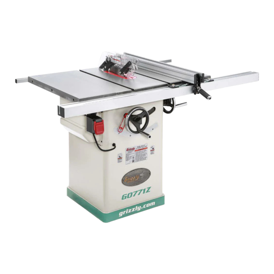
Model G0771Z
***IMPORTANT UPDATE***
For Machines Mfd. Since 07/21
and Owner's Manual Revised 05/21
Advertisement
Table of Contents

Related Manuals for Grizzly G0771Z


Summary of Contents for Grizzly G0771Z
- Page 1 ***IMPORTANT UPDATE*** For Machines Mfd. Since 07/21 and Owner's Manual Revised 05/21 For questions or help with this product contact Tech Support at (570) 546-9663 or techsupport@grizzly.com The following changes were recently made since the owner's manual was printed: •...
- Page 2 #999999 PRINTED IN TAIWAN CHINA V1.01.16 5012917 COPYRIGHT © OCTOBER, 2016 BY GRIZZLY INDUSTRIAL, INC., REVISED MAY, 2021 (JP) WARNING: NO PORTION OF THIS MANUAL MAY BE REPRODUCED IN ANY SHAPE OR FORM WITHOUT THE WRITTEN APPROVAL OF GRIZZLY INDUSTRIAL, INC.
- Page 3 This manual provides critical safety instructions on the proper setup, operation, maintenance, and service of this machine/tool. Save this document, refer to it often, and use it to instruct other operators. Failure to read, understand and follow the instructions in this manual may result in fire or serious personal injury—including amputation, electrocution, or death.
-
Page 4: Table Of Contents
Table of Contents INTRODUCTION ..........2 SECTION SHOP-MADE SAFETY ACCESSORIES ..........46 Machine Description ........2 Contact Info............ 2 Featherboards ..........46 Manual Accuracy ........... 2 Push Sticks ..........49 Identification ........... 3 Push Blocks ..........50 Controls & Components ......... 4 Narrow-Rip Auxiliary Fence &... -
Page 5: Introduction
We want your feedback on this manual. What did you like about it? Where could it be improved? Please take a few minutes to give us feedback. Grizzly Documentation Manager Manufacture Date P.O. Box 2069 Bellingham, WA 98227-2069 Email: manuals@grizzly.com Serial Number Model G0771Z (Mfd. Since 01/21) -
Page 6: Identification
4" Dust Handle Port Figure 1. Model G0771Z identification of main controls and components. or Your Own Safety Read Instruction Manual Before Operating Saw a) Wear eye protection. b) Use saw-blade guard and spreader for every operation for which it can be used, including all through sawing. -
Page 7: Controls & Components
Note: Paddle cover must be lifted to access ON switch. Figure 3. Blade adjustment handwheels and locks. E. Fence Lock: Locks fence when pushed down, unlocks fence when pulled up. Figure 2. ON/OFF switch. Figure 4. Fence lock handle. Model G0771Z (Mfd. Since 01/21) -
Page 8: Glossary Of Terms
Refer to Non-Through Cut: A cut in which the blade does Page 28 for more information. not cut through the top of the workpiece. Refer to Page 27 for more details. Model G0771Z (Mfd. Since 01/21) -
Page 9: Machine Data Sheet
MACHINE DATA SHEET Customer Service #: (570) 546-9663 · To Order Call: (800) 523-4777 · Fax #: (800) 438-5901 MODEL G0771Z 10" HYBRID TABLE SAW WITH T‐SHAPED FENCE Product Dimensions: Weight................................286 lbs. Width (side-to-side) x Depth (front-to-back) x Height............57-1/2 x 37-1/2 x 35-1/2 in. - Page 10 The information contained herein is deemed accurate as of 10/10/2016 and represents our most recent product specifications. Model G0771Z PAGE 2 OF 3 Due to our ongoing improvement efforts, this information may not accurately describe items previously purchased. Model G0771Z (Mfd. Since 01/21)
-
Page 11: Section 1: Safety
Never operate under the influence of drugs or injury or blindness from flying particles. Everyday alcohol, when tired, or when distracted. eyeglasses are NOT approved safety glasses. Model G0771Z (Mfd. Since 01/21) - Page 12 Make sure they are properly installed, you experience difficulties performing the intend- undamaged, and working correctly BEFORE ed operation, stop using the machine! Contact our operating machine. Technical Support at (570) 546-9663. Model G0771Z (Mfd. Since 01/21)
-
Page 13: Additional Safety For Table Saws
In event of an covered wood products, and some plastics. Never accident, these will often take damage that would cut materials not intended for this saw. have occurred to hands/fingers. -10- Model G0771Z (Mfd. Since 01/21) -
Page 14: Preventing Kickback
Making a deep area being struck by the flying stock, it is non-through cut will greatly increase the often the case that the operator’s hands are chance of kickback. pulled into the blade during kickback. -11- Model G0771Z (Mfd. Since 01/21) -
Page 15: Section 2: Power Supply
Nominal Voltage ..208V, 220V, 230V, 240V meets the specified circuit requirements. Cycle ............60 Hz Phase ........... Single-Phase Power Supply Circuit ......15 Amps Plug/Receptacle ......NEMA 6-15 -12- Model G0771Z (Mfd. Since 01/21) - Page 16 The plug must only be inserted into a matching receptacle (see following figure) that is properly installed and grounded in accordance with all local codes and ordinances. -13- Model G0771Z (Mfd. Since 01/21)
-
Page 17: Converting Voltage To 240V
NEMA standard 6-15 plug wiring is provided • Wire Cutters/Stripper ........1 on Page 74. To convert the Model G0771Z to 240V: DISCONNECT SAW FROM POWER! Cut off existing 5-15 plug. Open motor junction box, then loosen two wire nuts indicated in Figure 7. -
Page 18: Section 3: Setup
IMPORTANT: Save all packaging materials until you are completely satisfied with the machine and have resolved any issues between Grizzly or the shipping agent. You MUST have the original pack- aging to file a freight claim. It is also extremely helpful if you need to return your machine later. -
Page 19: Hardware Recognition Chart
Hardware Recognition Chart USE THIS CHART TO MATCH UP HARDWARE DURING THE INVENTORY AND ASSEMBLY PROCESS. Flat Head Screw -16- Model G0771Z (Mfd. Since 01/21) -
Page 20: Inventory
Button Head Cap Screws M5-.8 x 16 ....16 Tap Screws 3.5 x 9.5 V2.06.19 ......2 Figure 9. Main table saw unit. Flat Washer 6 x 20mm ........1 Set Screws M8-1.25 x 10 ........6 -17- Model G0771Z (Mfd. Since 01/21) -
Page 21: Cleanup
Figure 13. T23692 Orange Power Degreaser. Repeat Steps 2–3 as necessary until clean, then coat all unpainted surfaces with a quality metal protectant to prevent rust. -18- Model G0771Z (Mfd. Since 01/21) -
Page 22: Site Considerations
Only install in an Shadows, glare, or strobe effects that may distract access restricted location. or impede the operator must be eliminated. = Power Connection Dust Port " Min. 30" " 64" Figure 14. Minimum working clearances. -19- Model G0771Z (Mfd. Since 01/21) -
Page 23: Assembly
10mm lock washers (see Phillips head screws (see Figure 17). Figure 15). Do not fully tighten cap screws at this time. Motor Cover Figure 17. Motor cover installed. Figure 15. Extension wings installed. -20- Model G0771Z (Mfd. Since 01/21) - Page 24 (8) M8-1.25 x 25 cap screws, as shown in Figure 23. Secure outer four cap screws with M8-1.25 hex nuts. Rear Fence Scale Rail Slot Figure 20. Hex bolt positioned in front fence rail slot. Figure 23. Rear fence rail mounted. -21- Model G0771Z (Mfd. Since 01/21)
- Page 25 Figure 25. Fence Notch Star Knob Front Fence Rail Figure 27. Fence installed on front rail. Figure 25. Handwheel installed. 14. Install saw blade as instructed in Blade Installation on Page 30. -22- Model G0771Z (Mfd. Since 01/21)
- Page 26 — If crosshair does not align with zero mark on scale, loosen fence scale window screws, move crosshair over zero mark, then carefully tighten screws. 27. Lower blade completely. -23- Model G0771Z (Mfd. Since 01/21)
-
Page 27: Dust Collection
Tug hose to make sure it does not come off. Note: A tight fit is necessary for proper per- formance. Figure 32. Miter guage handle and washer. Figure 33. Example of dust hose attached to dust port. -24- Model G0771Z (Mfd. Since 01/21) -
Page 28: Test Run
Turn machine ON, verify motor operation, Blade Tilt Calibration (Page 60). then turn machine OFF. Miter Slot to Blade Parallelism (Page 62). The motor should run smoothly and without unusual problems or noises. Table/Dado Insert Adjustment (Page 70). -25- Model G0771Z (Mfd. Since 01/21) -
Page 29: Section 4: Operations
Read books/magazines or get formal training before beginning any proj- ects. Regardless of the content in this sec- tion, Grizzly Industrial will not be held liable for accidents caused by lack of training. -26- Model G0771Z (Mfd. Since 01/21) -
Page 30: Workpiece Inspection
On the contrary, a workpiece supported on the bowed side will rock during a cut and could cause kickback or severe injury. -27- Model G0771Z (Mfd. Since 01/21) -
Page 31: Blade Requirements
• Alternate top bevel tooth profile • Small hook angle and a shallow gullet Blade Size Requirements: • Body Thickness: 0.060"-0.086" (1.5-2.1mm) • Kerf (Tooth) Thickness: 0.094"-0.126" (2.4-3.2mm) Alternate Bevel Figure 38. Crosscutting blade. -28- Model G0771Z (Mfd. Since 01/21) - Page 32 Laminate blade features: • Best for cutting plywood or veneer • 40-80 teeth Figure 41. Stacked dado blade. • Triple chip tooth profile • Very shallow gullet Triple Chip Blade Figure 40. Laminate blade. -29- Model G0771Z (Mfd. Since 01/21)
-
Page 33: Blade Installation
Use included arbor wrenches to loosen and remove arbor nut, flange, and blade (see Figure 42). Arbor nut has right hand threads; rotate counterclockwise to loosen. Figure 42. Example of removing table saw blade. -30- Model G0771Z (Mfd. Since 01/21) -
Page 34: Blade Guard Assembly
Riving Knife workpiece and return to the table surface. Lock Lever Insert Adjustment Screw (1 of 5 shown) Figure 45. Lock lever used to secure spreader/ riving knife. -31- Model G0771Z (Mfd. Since 01/21) - Page 35 It should also swing up high enough to accommodate the workpiece. Pawl Figure 49. Pawls in resting position. Figure 47. Blade guard installed. -32- Model G0771Z (Mfd. Since 01/21)
-
Page 36: Riving Knife
Minimum 1mm Height Difference Maximum 5mm Figure 50. Pawls removed. Figure 51. Example of height difference between riving knife and blade. -33- Model G0771Z (Mfd. Since 01/21) - Page 37 (see Figure 53). we strongly recommend that you use the blade guard assembly for through cuts. Spreader/ Upper Holes Riving Knife Bracket Slot Lock Lever Figure 53. Lock lever used to secure spreader. -34- Model G0771Z (Mfd. Since 01/21)
-
Page 38: Ripping
Failure to do this could result in serious personal injury or death. Plug saw into power source, turn it ON, and allow it to reach full speed. Note: Jointed edge of workpiece must slide against fence during cutting operation. -35- Model G0771Z (Mfd. Since 01/21) -
Page 39: Crosscutting
Proceed to make cut in same manner as described in Crosscutting instructions. Turn saw OFF and allow blade to come to a complete stop before removing cutoff piece. Failure to follow this warning could result in severe lacerations or amputation. -36- Model G0771Z (Mfd. Since 01/21) -
Page 40: Blade Tilt/Bevel Cuts
Blade Tilt/Bevel Cuts The Model G0771Z can accommodate dado blades up to 10" in diameter. However, you MUST install the included riving knife while using a 10" diameter dado blade, as it provides a barrier When the blade tilt adjustment bolts are properly... - Page 41 Set saw up for type of cut you need to make, depending on whether it is a rip cut (Page 35) or crosscut (Page 36). -38- Model G0771Z (Mfd. Since 01/21)
-
Page 42: Rabbet Cutting
To minimize your risk of Workpiece serious personal injury, ensure that stock is flat and straight, and make multiple light cuts (rather than one deep cut) to achieve the desired cutting depth. Figure 62. Additional single-blade dado cuts. -39- Model G0771Z (Mfd. Since 01/21) - Page 43 — If workpiece is very tall, or is unstable when placed against fence, lay it flat on — If cut is satisfactory, repeat cut with table and use a dado blade to perform rab- workpiece. bet cut. -40- Model G0771Z (Mfd. Since 01/21)
-
Page 44: Resawing
Note: To determine the maximum resawing height Blade for this table saw, find the maximum blade height, then double it and subtract ⁄ ". Fence Workpiece Figure 66. Example of second cut to create a rabbet. -41- Model G0771Z (Mfd. Since 01/21) - Page 45 Assembled Auxiliary Fence angle with larger board in vertical position, as shown in Figure 67, then fasten together with wood screws. Figure 68. Example of auxiliary fence attached to Model G0771Z fence face. #8 x 2" Tools Needed: ⁄ "...
- Page 46 Place auxiliary fence board against fence face. Place a thin metal shim (such as a ruler) Replace fence cap. between table and bottom of auxiliary fence board to ensure adequate clearance between fence board and table. Clamp in position. -43- Model G0771Z (Mfd. Since 01/21)
- Page 47 Attach auxiliary fence and set it to desired width. " Connection Note: When determining correct width, don't forget to account for blade kerf and inaccuracy of fence scale while auxiliary fence is installed. Figure 72. Ideal completed resaw cut. -44- Model G0771Z (Mfd. Since 01/21)
- Page 48 11. Turn OFF table saw, then separate parts of workpiece and hand plane remaining ridge to remove it. 12. When finished resawing, remove resaw bar- rier and auxiliary fence, then re-install blade guard/spreader or riving knife and standard table insert. -45- Model G0771Z (Mfd. Since 01/21)
-
Page 49: Section 5: Shop-Made Safety Accessories
Step 3 will bend without breaking. Cut a 30º angle at one end of board. Only Steps 1–3 are required to make a clamp-mounted featherboard. Refer to Page 48 for instructions on clamping. -46- Model G0771Z (Mfd. Since 01/21) - Page 50 Now, proceed to Mounting Featherboard in Drill a ⁄ " hole in center of bar, then counter- Miter Slot on Page 48. sink bottom to fit a ⁄ "-20 flat head screw. -47- Model G0771Z (Mfd. Since 01/21)
- Page 51 Note: The featherboard should be placed firmly enough against workpiece to keep it against fence but not so tight that it is difficult to feed workpiece. -48- Model G0771Z (Mfd. Since 01/21)
-
Page 52: Push Sticks
⁄ " Grid from the blade! Figure 81. Template for a basic shop-made push stick (not shown at actual size). -49- Model G0771Z (Mfd. Since 01/21) -
Page 53: Push Blocks
Lip for pushing workpiece ⁄ " Grid 9"−10" Minimum Length Figure 84. Template for a shop-made push block (shown at 50% of full size). -50- Model G0771Z (Mfd. Since 01/21) -
Page 54: Narrow-Rip Auxiliary Fence & Push Block
Attach handle to base with #8 x 1 ⁄ " wood screws, and attach lip to base with cyanoac- Length of Table rylate-type wood glue. Saw Rip Fence ⁄ " Figure 85. Auxiliary fence dimensions. -51- Model G0771Z (Mfd. Since 01/21) - Page 55 Failure to follow this warning could result in serious personal injury. Re-install spreader pawls when finished using auxiliary fence and push block. -52- Model G0771Z (Mfd. Since 01/21)
-
Page 56: Outfeed & Support Tables
Crosscut Sled Support Outfeed Table Table Figure 92. Example of crosscut sled. Figure 91. Example of outfeed & support tables. -53- Model G0771Z (Mfd. Since 01/21) -
Page 57: Section 6: Accessories
Specifications: 450 CFM, 7.2" To reduce this risk, only install accessories static pressure, 2 cubic foot bag, and 30 micron recommended for this machine by Grizzly. filter. Motor is 1HP, 110V/220V, 14A/7A. NOTICE Model G0710 Refer to our website or latest catalog for additional recommended accessories. - Page 58 Adjusts from 20" x 20" to 29 ⁄ " x 29 ⁄ ". Figure 97. Forrest Woodworker II Saw Blade. Figure 100. D2057A Heavy-Duty Mobile Base. www.grizzly.com 1-800-523-4777 order online at or call -55- Model G0771Z (Mfd. Since 01/21)
-
Page 59: Section 7: Maintenance
• Check/replace belt for proper tension, dam- age or wear (Page 72). Every 6–12 Months: • Lubricate trunnion slides (Page 57). • Lubricate worm gear (Page 57). • Lubricate leadscrew (Page 57). -56- Model G0771Z (Mfd. Since 01/21) -
Page 60: Lubrication
Move the blade tilt back and forth to spread the grease (see Figure 101). Figure 103. Leadscrew. Front Trunnion Slide Figure 101. Trunnion slide (only front slide shown). -57- Model G0771Z (Mfd. Since 01/21) -
Page 61: Section 8: Service
7. Arbor pulley loose. 7. Retighten/replace arbor pulley. 8. Arbor bearings at fault. 8. Replace arbor housing bearings; replace arbor. 9. Motor bearings at fault. 9. Test by rotating shaft; grinding/loose shaft requires bearing replacement. -58- Model G0771Z (Mfd. Since 01/21) - Page 62 5. Adjust table so miter slot is parallel with blade at 90° 90°. (Page 62). Workpiece catches 1. Table/dado insert out of adjustment. 1. Adjust table/dado insert so it is perfectly flush with on table/dado insert table surface (Page 70). or table throat during cutting operation. -59- Model G0771Z (Mfd. Since 01/21)
-
Page 63: Blade Tilt Calibration
90°, then tighten stop nuts against each other and replace motor cover. Note: Rotating stop nuts clockwise adjusts blade further to right; rotating them counter- clockwise adjusts blade to left. -60- Model G0771Z (Mfd. Since 01/21) - Page 64 Page 60. ments need to be made. Proceed to Step 8. — If blade is not 45° to table, you will need to adjust 45° limiting block. Proceed to Step 4. Remove rear access panel. -61- Model G0771Z (Mfd. Since 01/21)
-
Page 65: Miter Slot To Blade Parallelism
— If blade tip does not touch end of adjust- able square similar to first measurement, table will need to be adjusted. Proceed to Blade tilted to 0º Step 6. Front Figure 109. Example of adjusting blade to miter slot. -62- Model G0771Z (Mfd. Since 01/21) - Page 66 45°, one end of table will need to be shimmed higher with metal shim stock. Continue to Step 9. Figure 113. Shim procedure diagram B. Loosen (4) table mounting bolts from Step 6. -63- Model G0771Z (Mfd. Since 01/21)
-
Page 67: Spreader Or Riving Knife Alignment
"Alignment Zone," as shown in Figure 115. Top Alignment Bottom Alignment Figure 114. Example of checking top and bottom riving knife parallelism with blade. Alignment Zone Spreader or Riving Knife Blade Figure 115. Spreader/riving knife alignment zone. -64- Model G0771Z (Mfd. Since 01/21) - Page 68 Steps 1–3 in Checking Alignment to determine if it is parallel with blade and inside "Alignment Zone." — If necessary, remove spreader/riving knife to straighten it. — If you cannot straighten spreader/riving knife properly, replace it. -65- Model G0771Z (Mfd. Since 01/21)
-
Page 69: Adjusting Fence
(Side View) Fence " Gap Rear Front Set Table Bearing Screws Shaft (1 of 2) Figure 118. Fence height is adjusted by two front set screws and rear bearing shaft. -66- Model G0771Z (Mfd. Since 01/21) - Page 70 Bearing Shaft Re-install fence and check clamping pres- sure of lock handle. Roller Repeat Steps 1–5 as necessary to achieve Bearing desired results. Outer Jam Nut Figure 121. Rear adjustment area for leveling fence. -67- Model G0771Z (Mfd. Since 01/21)
-
Page 71: Calibrating Fence To Blade
Blade Fence is Parallel to Miter Slot, which is Parallel to Blade Figure 124. Checking fence parallelism with blade. -68- Model G0771Z (Mfd. Since 01/21) -
Page 72: Fence Scale Calibration
12" at front and back. and is not adjusted parallel with blade. If it is not, then adjust indicator window to match width of workpiece. Right Indicator Window Left Indicator Window Figure 126. Fence indicator windows. -69- Model G0771Z (Mfd. Since 01/21) - Page 73 Figure 127 and either loosen screws to raise insert, or tighten screws to lower it. Repeat Steps 2–3 until insert is perfectly flush with surface of table. Figure 127. Location of table/dado insert holes with adjustment screws. -70- Model G0771Z (Mfd. Since 01/21)
-
Page 74: Miter Gauge Adjustments
No adjustments are nec- essary. — If square does not touch miter body and blade evenly, then proceed to Step 5. Remove miter gauge from miter slot. -71- Model G0771Z (Mfd. Since 01/21) -
Page 75: Tensioning & Replacing Belt
Figure 130. Components used to tension or remove belt. Use blade height handwheel to lower motor. When motor starts to pull blade down with it, belt is tensioned. Retighten blade tension hex bolt, then re- install motor cover. -72- Model G0771Z (Mfd. Since 01/21) -
Page 76: Section 9: Wiring
Technical Support at (570) 546-9663. The photos and diagrams included in this section are best viewed in color. You can view these pages in color at www.grizzly.com. -73- Model G0771Z (Mfd. Since 01/21) -
Page 77: Wiring Diagram
350VAC Start Start Capacitor Capacitor 150MFD CD60 200MFD 250VAC 250VAC Motor Re-wired for 240V Ground Capacitor CBB60 30MFD 350VAC Start Start Capacitor Capacitor 150MFD CD60 200MFD 250VAC 250VAC READ ELECTRICAL SAFETY -74- Model G0771Z (Mfd. Since 01/21) ON PAGE 73! -
Page 78: Electrical Components
Electrical Components Figure 131. Switch wiring. Figure 133. Motor wiring at 120V. Figure 134. Motor wiring label inside junction box. Figure 132. Capacitors. Figure 135. Motor label. READ ELECTRICAL SAFETY -75- Model G0771Z (Mfd. Since 01/21) ON PAGE 73! -
Page 79: Section 10: Parts
Please Note: We do our best to stock replacement parts whenever possible, but we cannot guarantee that all parts shown here are available for purchase. Call (800) 523-4777 or visit our online parts store at www.grizzly.com to check for availability. - Page 80 P0771Z124 DADO TABLE INSERT P0771Z067 BLADE GUARD P0771Z125 HEX WRENCH 2.5MM P0771Z068 TILT SHAFT P0771Z126 FLAT WASHER 6MM P0771Z069 RIVING GUIDE BUY PARTS ONLINE AT GRIZZLY.COM! -77- Model G0771Z (Mfd. Since 02/20) Scan QR code to visit our Parts Store.
-
Page 81: Cabinet
212 P0771Z212 PUSH STICK 206 P0771Z206 BUTTON HD CAP SCR M5-.8 X 12 213 P0771Z213 PHLP HD SCR M3-.5 X 16 -78- BUY PARTS ONLINE AT GRIZZLY.COM! Model G0771Z (Mfd. Since 01/21) Scan QR code to visit our Parts Store. -
Page 82: Fence & Rails
PHLP HD SCREW M6-1 X 8 P0771Z361 TAP SCREW M4.2 X 13 P0771Z332 HEX BOLT M10-1.5 X 45 P0771Z362 FENCE PLATE P0771Z333 LOCK NUT M10-1.5 -79- BUY PARTS ONLINE AT GRIZZLY.COM! Model G0771Z (Mfd. Since 01/21) Scan QR code to visit our Parts Store. -
Page 83: Blade Guard
P0771Z411 GUARD RAIL P0771Z424 CAP SCREW M5-.8 X 30 P0771Z412 PHLP HD SCR M5-.8 X 25 P0771Z425 BLADE GUARD WINDOW COVER -80- BUY PARTS ONLINE AT GRIZZLY.COM! Model G0771Z (Mfd. Since 01/21) Scan QR code to visit our Parts Store. -
Page 84: Miter Gauge
P0771Z521 FLAT HD SCR 1/4-28 X 5/16 P0771Z510 MITER SCALE P0771Z522 SET SCREW 10-32 X 1/4 P0771Z511 SPRING PLATE P0771Z523 MITER BAR GUIDE WASHER P0771Z512 MITER HANDLE -81- BUY PARTS ONLINE AT GRIZZLY.COM! Model G0771Z (Mfd. Since 01/21) Scan QR code to visit our Parts Store. -
Page 85: Labels & Cosmetics
Safety labels help reduce the risk of serious injury caused by machine hazards. If any label comes off or becomes unreadable, the owner of this machine MUST replace it in the original location before resuming operations. For replacements, contact (800) 523-4777 or www.grizzly.com. -82- BUY PARTS ONLINE AT GRIZZLY.COM! -
Page 88: Warranty & Returns
WARRANTY & RETURNS Grizzly Industrial, Inc. warrants every product it sells for a period of 1 year to the original purchaser from the date of purchase. This warranty does not apply to defects due directly or indirectly to misuse, abuse, negligence, accidents, repairs or alterations or lack of maintenance.