Bosch Rexroth IndraControl VSB 40.1 Project Planning Manual
Control cabinet pc
Hide thumbs
Also See for Rexroth IndraControl VSB 40.1:
- Project planning manual (80 pages) ,
- Project planning manual (87 pages)

Related Manuals for Bosch Rexroth IndraControl VSB 40.1


Summary of Contents for Bosch Rexroth IndraControl VSB 40.1
- Page 1 Electric Drives Linear Motion and and Controls Hydraulics Assembly Technologies Pneumatics Service...
- Page 2 Bosch Rexroth AG DOK-SUPPL*-VSB*40.1***-PR03-EN-P Rexroth IndraControl VSB 40.1 Control Cabinet PC Title Rexroth IndraControl VSB 40.1 Control Cabinet PC Type of Documentation Project Planning Manual Document Typecode DOK-SUPPL*-VSB*40.1***-PR03-EN-P Internal File Reference RS-aba347a30fe8727c0a6846a00116c43c-1-en-US-3 Purpose of Documentation This documentation describes the control cabinet PC VSB 40.1.
-
Page 3: Table Of Contents
DOK-SUPPL*-VSB*40.1***-PR03-EN-P Bosch Rexroth AG I/83 Rexroth IndraControl VSB 40.1 Control Cabinet PC Table of Contents Table of Contents Page System Presentation...................... 5 Brief Description VSB 40.1........................5 Operating System........................... 5 Commissioning............................6 Important Instructions for Use..................7 Appropriate Use ............................. 7 2.1.1... - Page 4 II/83 Bosch Rexroth AG DOK-SUPPL*-VSB*40.1***-PR03-EN-P Rexroth IndraControl VSB 40.1 Control Cabinet PC Table of Contents Page Mounting the VSB 40.1 Variant NN...................... 28 5.2.1 Horizontal Mounting with Connector Panel in Forward Direction............28 5.2.2 Vertical Mounting with Connector Panel in Forward Direction............29 5.2.3...
- Page 5 DOK-SUPPL*-VSB*40.1***-PR03-EN-P Bosch Rexroth AG III/83 Rexroth IndraControl VSB 40.1 Control Cabinet PC Table of Contents Page Jumper Setting on the Motherboard....................57 Maintenance and Installation..................59 General Information..........................59 CMOS Battery............................59 Connecting the Uninterruptible Power Supply (UPS)................59 8.3.1 General Information...........................
- Page 6 IV/83 Bosch Rexroth AG DOK-SUPPL*-VSB*40.1***-PR03-EN-P Rexroth IndraControl VSB 40.1 Control Cabinet PC...
-
Page 7: System Presentation
DOK-SUPPL*-VSB*40.1***-PR03-EN-P Bosch Rexroth AG 5/83 Rexroth IndraControl VSB 40.1 Control Cabinet PC System Presentation System Presentation Brief Description VSB 40.1 The VSB 40.1 is a control cabinet PC that forms a PC-based operator terminal when combined with a VDP 16 or VDP 40 display. Depending on the application and configuration, the operator terminal can also fulfill control functionalities. -
Page 8: Commissioning
6/83 Bosch Rexroth AG DOK-SUPPL*-VSB*40.1***-PR03-EN-P Rexroth IndraControl VSB 40.1 Control Cabinet PC System Presentation Commissioning Mount the device properly, see also chapter 5 "Dimensions and Installation Notes" on page 27. Then, connect the device to the power supply and, if... -
Page 9: Important Instructions For Use
The user alone carries all responsibility of the risks. Before using Bosch Rexroth products, make sure that all the pre-requisites for appropriate use of the products are satisfied: ●... -
Page 10: Inappropriate Use
This includes, for example, operation under water, in the case of extreme temperature fluctuations or extreme maximum tempera‐ tures or if ● Bosch Rexroth has not explicitly released the intended applications. Do also note the information given in the general safety instructions! -
Page 11: Safety Instructions For Electric Drives And Controls
DOK-SUPPL*-VSB*40.1***-PR03-EN-P Bosch Rexroth AG 9/83 Rexroth IndraControl VSB 40.1 Control Cabinet PC Safety Instructions for Electric Drives and Controls Safety Instructions for Electric Drives and Controls Definitions of Terms Application Documentation Application documentation comprises the entire documentation used to inform the user of the product about the use and safety-relevant features for config‐... -
Page 12: General Information
You must follow these safety instructions. ● Bosch Rexroth is not liable for damages resulting from failure to observe the safety instructions. ●... -
Page 13: Hazards By Improper Use
DOK-SUPPL*-VSB*40.1***-PR03-EN-P Bosch Rexroth AG 11/83 Rexroth IndraControl VSB 40.1 Control Cabinet PC Safety Instructions for Electric Drives and Controls concept in which measures of risk reduction for personal safety depend on electrical, electronic or programmable control systems. ● The information given in the application documentation with regard to the use of the delivered components contains only examples of applications and suggestions. - Page 14 12/83 Bosch Rexroth AG DOK-SUPPL*-VSB*40.1***-PR03-EN-P Rexroth IndraControl VSB 40.1 Control Cabinet PC Safety Instructions for Electric Drives and Controls ● Risk of injury by improper handling! Injury by crushing, shearing, cutting, hitting! ● Risk of injury by improper handling of batteries! ●...
-
Page 15: Instructions With Regard To Specific Dangers
DOK-SUPPL*-VSB*40.1***-PR03-EN-P Bosch Rexroth AG 13/83 Rexroth IndraControl VSB 40.1 Control Cabinet PC Safety Instructions for Electric Drives and Controls Instructions with Regard to Specific Dangers 3.3.1 Protection Against Contact With Electrical Parts and Housings This section concerns components of the electric drive and control system with voltages of more than 50 volts. -
Page 16: Protective Extra-Low Voltage As Protection Against Electric Shock
Protective extra-low voltage is used to allow connecting devices with basic in‐ sulation to extra-low voltage circuits. On components of an electric drive and control system provided by Bosch Rexroth, all connections and terminals with voltages between 5 and 50 volts are PELV ("Protective Extra-Low Voltage") systems. - Page 17 DOK-SUPPL*-VSB*40.1***-PR03-EN-P Bosch Rexroth AG 15/83 Rexroth IndraControl VSB 40.1 Control Cabinet PC Safety Instructions for Electric Drives and Controls ● Improper or wrong wiring or cable connection ● Operator errors ● Wrong input of parameters before commissioning ● Malfunction of sensors and encoders ●...
-
Page 18: Protection Against Magnetic And Electromagnetic Fields During Operation And Mounting
16/83 Bosch Rexroth AG DOK-SUPPL*-VSB*40.1***-PR03-EN-P Rexroth IndraControl VSB 40.1 Control Cabinet PC Safety Instructions for Electric Drives and Controls ● The standard equipment motor holding brake or an external holding brake controlled by the drive controller is not sufficient to guarantee personal safety! ●... -
Page 19: Protection During Handling And Mounting
DOK-SUPPL*-VSB*40.1***-PR03-EN-P Bosch Rexroth AG 17/83 Rexroth IndraControl VSB 40.1 Control Cabinet PC Safety Instructions for Electric Drives and Controls ● After switching chokes, supply units and drive controllers off, wait 15 mi‐ nutes to allow them to cool down before touching them. -
Page 20: Protection Against Pressurized Systems
18/83 Bosch Rexroth AG DOK-SUPPL*-VSB*40.1***-PR03-EN-P Rexroth IndraControl VSB 40.1 Control Cabinet PC Safety Instructions for Electric Drives and Controls 3.3.8 Protection Against Pressurized Systems According to the information given in the Project Planning Manuals, motors and components cooled with liquids and compressed air can be partially supplied with externally fed, pressurized media, such as compressed air, hydraulics oil, cooling liquids and cooling lubricants. - Page 21 DOK-SUPPL*-VSB*40.1***-PR03-EN-P Bosch Rexroth AG 19/83 Rexroth IndraControl VSB 40.1 Control Cabinet PC Safety Instructions for Electric Drives and Controls NOTICE In case of non-compliance with this safety instruction, property damage could occur.
- Page 22 20/83 Bosch Rexroth AG DOK-SUPPL*-VSB*40.1***-PR03-EN-P Rexroth IndraControl VSB 40.1 Control Cabinet PC...
-
Page 23: Technical Data
DOK-SUPPL*-VSB*40.1***-PR03-EN-P Bosch Rexroth AG 21/83 Rexroth IndraControl VSB 40.1 Control Cabinet PC Technical Data Technical Data PC Box PC box Type E Processor Celeron with minimum 2 GHz Chip set Integrated graphics controller with a maximum of 8 MB video memory 512 MB / 1.024 MB... -
Page 24: Voltage Supply
22/83 Bosch Rexroth AG DOK-SUPPL*-VSB*40.1***-PR03-EN-P Rexroth IndraControl VSB 40.1 Control Cabinet PC Technical Data Output voltages: Current Tolerances Min. Max. +3.3 V ± 5 % 0.5 A 20 A ± 5 % +5 V 0.5 A 25 A ± 5 % +12 V 1.0 A... -
Page 25: Ambient Conditions
DOK-SUPPL*-VSB*40.1***-PR03-EN-P Bosch Rexroth AG 23/83 Rexroth IndraControl VSB 40.1 Control Cabinet PC Technical Data Ambient Conditions In operation Storage / Transport Max. surrounding air temperature +5 °C ... +45 ℃ -20 ℃ to +60 ℃ Exception: 230 V UPS (see chapter 8.3 "Connect‐... -
Page 26: Ce Marking
24/83 Bosch Rexroth AG DOK-SUPPL*-VSB*40.1***-PR03-EN-P Rexroth IndraControl VSB 40.1 Control Cabinet PC Technical Data Standard Meaning EN 60 068-2-6 Vibration test EN 60 068-2-27 Shock test Fig.4-5: Used standards CE Marking 4.6.1 Declaration of Conformity The electronic products described in the project planning manual comply with... -
Page 27: Wear Parts
DOK-SUPPL*-VSB*40.1***-PR03-EN-P Bosch Rexroth AG 25/83 Rexroth IndraControl VSB 40.1 Control Cabinet PC Technical Data The devices of the VSB 40.1 product family are certificated according to ● UL508 (Industrial Control Equipment) and ● C22.2 no. 142-M1987 (CSA) UL file no. E210730 However, there can be combinations or stages of expansions with limited or missing certification. -
Page 28: Compatibility Test
26/83 Bosch Rexroth AG DOK-SUPPL*-VSB*40.1***-PR03-EN-P Rexroth IndraControl VSB 40.1 Control Cabinet PC Technical Data Fans are mechanical wear components, whose service life is extremely tem‐ perature-dependent. For the fan integrated in the housing, the following service life is specified by the manufacturer:... -
Page 29: Dimensions And Installation Notes
DOK-SUPPL*-VSB*40.1***-PR03-EN-P Bosch Rexroth AG 27/83 Rexroth IndraControl VSB 40.1 Control Cabinet PC Dimensions and Installation Notes Dimensions and Installation Notes General Information To meet the various installation requirements, the VSB 40.1 equipped with an optional drive is available in different variants. Depending on the provided dis‐... -
Page 30: Mounting The Vsb 40.1 Variant Nn
Fig.5-2: VSB 40.1, variant LS (drive in connector direction) Mounting direction Any horizontal and vertical mounting direction is permissible. However, Bosch Rexroth recommends the mounting directions illustrated below. Minimum distances Do observe the distance required for all installation positions of connectors and cables as well as for the opening drive. -
Page 31: Vertical Mounting With Connector Panel In Forward Direction
DOK-SUPPL*-VSB*40.1***-PR03-EN-P Bosch Rexroth AG 29/83 Rexroth IndraControl VSB 40.1 Control Cabinet PC Dimensions and Installation Notes Fig.5-4: Dimensions for horizontal mounting with connector panel in forward di‐ rection 5.2.2 Vertical Mounting with Connector Panel in Forward Direction Fig.5-5: Vertical mounting with connector panel in forward direction... - Page 32 30/83 Bosch Rexroth AG DOK-SUPPL*-VSB*40.1***-PR03-EN-P Rexroth IndraControl VSB 40.1 Control Cabinet PC Dimensions and Installation Notes (Distance moun- (Abstand Montage- bohrungen) ting holes) (Ab . tand Montage- (Distance moun- bohrungen) ting holes) XDP S LAVE 52.7 52,7 (Distance moun- (Abstand Montage-...
-
Page 33: Mounting With Connector Panel On The Top Side
DOK-SUPPL*-VSB*40.1***-PR03-EN-P Bosch Rexroth AG 31/83 Rexroth IndraControl VSB 40.1 Control Cabinet PC Dimensions and Installation Notes 5.2.3 Mounting with Connector Panel on the Top Side Fig.5-7: Connector panel to the top side, optional drive in forward direction Fig.5-8: Dimensions when mounting the connector panel on the top side... -
Page 34: Mounting The Vsb 40.1 Variant Ls
32/83 Bosch Rexroth AG DOK-SUPPL*-VSB*40.1***-PR03-EN-P Rexroth IndraControl VSB 40.1 Control Cabinet PC Dimensions and Installation Notes Mounting the VSB 40.1 Variant LS 5.3.1 Mounting with Connector Panel in Forward Direction Fig.5-9: Mounting with connector panel and drive in forward direction Fig.5-10:... - Page 35 DOK-SUPPL*-VSB*40.1***-PR03-EN-P Bosch Rexroth AG 33/83 Rexroth IndraControl VSB 40.1 Control Cabinet PC Dimensions and Installation Notes ● Install the VSB 40.1 in a way ensuring easy access to the connector panel. ● Provide a minimum distance of 50 mm (on all sides of the device) for suf‐...
- Page 36 34/83 Bosch Rexroth AG DOK-SUPPL*-VSB*40.1***-PR03-EN-P Rexroth IndraControl VSB 40.1 Control Cabinet PC...
-
Page 37: Display And Operating Components
6.2.1 Display To display and operate the VSB 40.1 we recommend the VDP 16 and VDP 40 displays. These displays are especially designed by Bosch Rexroth for indus‐ trial applications. They are connected via the the G5 display interface with the VSB 40.1. - Page 38 36/83 Bosch Rexroth AG DOK-SUPPL*-VSB*40.1***-PR03-EN-P Rexroth IndraControl VSB 40.1 Control Cabinet PC Display and Operating Components Activating the VDP or an external If required, the user can select, whether the VDP connected with the G5 display monitor interface, the external monitor operated at the VGA connection or both should be addressed: 1.
- Page 39 DOK-SUPPL*-VSB*40.1***-PR03-EN-P Bosch Rexroth AG 37/83 Rexroth IndraControl VSB 40.1 Control Cabinet PC Display and Operating Components 4. In the left side of this tab you can select which monitor should be ad‐ dressed by clicking on the corresponding icon, provided that an external monitor is connected.
- Page 40 38/83 Bosch Rexroth AG DOK-SUPPL*-VSB*40.1***-PR03-EN-P Rexroth IndraControl VSB 40.1 Control Cabinet PC Display and Operating Components Fig.6-5: Hot keys tab...
-
Page 41: Pc Box
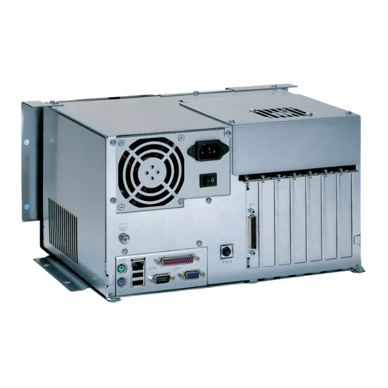
DOK-SUPPL*-VSB*40.1***-PR03-EN-P Bosch Rexroth AG 39/83 Rexroth IndraControl VSB 40.1 Control Cabinet PC PC Box PC Box View on the Connector Panel Fig.7-1: Position of connections of the different variants Interfaces 7.2.1 General Information NOTICE Malfunctions due to insufficient shielding! Use only shielded cables and metallic/conductive connector or coupling covers... -
Page 42: Overview
40/83 Bosch Rexroth AG DOK-SUPPL*-VSB*40.1***-PR03-EN-P Rexroth IndraControl VSB 40.1 Control Cabinet PC PC Box 7.2.2 Overview Des‐ Connection type Connector type (inte‐ Mating connector or igna‐ grated) cable (from outside) tion at hous‐ o XCO Serial interface: D-Sub male connector, D-Sub female con‐... -
Page 43: Settings Of The Serial Interface
DOK-SUPPL*-VSB*40.1***-PR03-EN-P Bosch Rexroth AG 41/83 Rexroth IndraControl VSB 40.1 Control Cabinet PC PC Box D-Sub male connector, 9-pin Transmission rate: Max. 115200 bits/s Handshake: Hardware and software handshake (XON, XOFF) Interrupt (IRQ): I/O address: AUTO (or 3F8H) BIOS presetting: Enabled Fig.7-3:... -
Page 44: Xusb Interfaces
42/83 Bosch Rexroth AG DOK-SUPPL*-VSB*40.1***-PR03-EN-P Rexroth IndraControl VSB 40.1 Control Cabinet PC PC Box D-Sub female connector, 25-pin Interrupt (IRQ): I/O address: AUTO or 378H (is recommended) Fig.7-5: XLPT, parallel interface XLPT1 Interface mode max. 3 m max. 3 m... -
Page 45: Ethernet Interface Xlan
DOK-SUPPL*-VSB*40.1***-PR03-EN-P Bosch Rexroth AG 43/83 Rexroth IndraControl VSB 40.1 Control Cabinet PC PC Box NOTICE Calling of the internal current monitoring if the current consumption exceeds 500 mA. The max. power consumption of one USB connector must not exceed 500 mA. -
Page 46: Xvga Interface
44/83 Bosch Rexroth AG DOK-SUPPL*-VSB*40.1***-PR03-EN-P Rexroth IndraControl VSB 40.1 Control Cabinet PC PC Box other values, if the data transmission shall occur with 10 Mbits/s and/or with 100 Mbits/s. NOTICE No or incorrect network data transmission if the data rate is set manually! Please note that the network card of the outstation has to be able to process the same data transmission rate. -
Page 47: Keyboard Interface Xkb
DOK-SUPPL*-VSB*40.1***-PR03-EN-P Bosch Rexroth AG 45/83 Rexroth IndraControl VSB 40.1 Control Cabinet PC PC Box NOTICE Setting incorrect resolutions and colors may destroy the monitor! Please note the technical data of the monitor and adapt the operating system parameters accordingly. Recommended monitors for external use are low-radiation models according to TCO95. -
Page 48: G5 Display Interface X71
46/83 Bosch Rexroth AG DOK-SUPPL*-VSB*40.1***-PR03-EN-P Rexroth IndraControl VSB 40.1 Control Cabinet PC PC Box PS/2 Mini DIN female connector, 6-pin Interrupt (IRQ): BIOS presetting: PS/2 mouse support: EnabledPS/2 Mouse: Auto detect Fig.7-15: XMouse - PS/2 mouse interface max. 1.5 m... -
Page 49: Pc Voltage Supply
DOK-SUPPL*-VSB*40.1***-PR03-EN-P Bosch Rexroth AG 47/83 Rexroth IndraControl VSB 40.1 Control Cabinet PC PC Box NOTICE Malfunction or no function due to devices with different display interface. Only connect devices with the same display interface. 7.2.12 PC Voltage Supply DC-24-V voltage supply This screw connection is used for device variants for DC 24 V. - Page 50 48/83 Bosch Rexroth AG DOK-SUPPL*-VSB*40.1***-PR03-EN-P Rexroth IndraControl VSB 40.1 Control Cabinet PC PC Box Fig.7-19: Safety isolating according to EN 60742 Interfering AC voltage components such as the ones resulting from an uncon‐ trolled three-phase bridge circuit without smoothing and with a ripple factor (see DIN 40110/10.75, Abschnitt 1.2) of 5 % are allowed.
- Page 51 DOK-SUPPL*-VSB*40.1***-PR03-EN-P Bosch Rexroth AG 49/83 Rexroth IndraControl VSB 40.1 Control Cabinet PC PC Box Fig.7-21: Wiring of the DC 24 V power connection to the VSB 40.1 DANGER Danger of death by high electric voltage ● Connect power supply units, which generate protective extra-low voltage (PELV) (24 V), only to supply voltages for which they are designed.
- Page 52 50/83 Bosch Rexroth AG DOK-SUPPL*-VSB*40.1***-PR03-EN-P Rexroth IndraControl VSB 40.1 Control Cabinet PC PC Box CAUTION The supply voltage must comply with overvolt‐ age category II! Otherwise the integrated pow‐ er supply unit might be destroyed. ⇒ Use an isolating transformer to generate the AC 230/115 V,, see fig.
-
Page 53: Optional Serial Interfaces
DOK-SUPPL*-VSB*40.1***-PR03-EN-P Bosch Rexroth AG 51/83 Rexroth IndraControl VSB 40.1 Control Cabinet PC PC Box Fig.7-24: AC 230 V voltage connection via isolating transformer Optional Serial Interfaces 7.3.1 General Information General Information According to the configuration, serial interfaces are available for the extension cards A5 and A6 on the slots. -
Page 54: Cfg-Vsn01E1-Nn-Nn-Nn-Nn-S3-S3 Serial Interfaces Rs232
52/83 Bosch Rexroth AG DOK-SUPPL*-VSB*40.1***-PR03-EN-P Rexroth IndraControl VSB 40.1 Control Cabinet PC PC Box Assignment Signal Ground DSR (Data Set Ready) RTS (Request to Send) CTS (Clear to Send) RI (Ring Indicator) Fig.7-25: Pin assignment RS232, D-sub male connector, 9-pin Fig.7-26:... -
Page 55: Xcom4 On Slot For A6 Extension Card
DOK-SUPPL*-VSB*40.1***-PR03-EN-P Bosch Rexroth AG 53/83 Rexroth IndraControl VSB 40.1 Control Cabinet PC PC Box XCOM4 on Slot for A6 Extension Card XCOM4 on slot for A6 extension Assignment card DCD (Data Carrier Detect) RX (Receive Data) TX (Transmit Data) DTR (Data Terminal Ready) -
Page 56: Xcom4 On Slot For A6 Extension Card
54/83 Bosch Rexroth AG DOK-SUPPL*-VSB*40.1***-PR03-EN-P Rexroth IndraControl VSB 40.1 Control Cabinet PC PC Box Assignment CTS (Clear to Send) RI (Ring Indicator) Fig.7-30: Pin assignment RS232, D-sub male connector, 9-pin XCOM4 on Slot for A6 Extension Card XCOM4 on slot for A6 extension... -
Page 57: Cfg-Vsn01E1-Nn-Nn-Nn-Nn-Nn-S6 Serial Interfaces Rs232 And Rs422 (Rexroth Standard)
DOK-SUPPL*-VSB*40.1***-PR03-EN-P Bosch Rexroth AG 55/83 Rexroth IndraControl VSB 40.1 Control Cabinet PC PC Box Motherboard, jumper setting Fig.7-33: Position of connectors and jumpers Motherboard 1070922809 = jumper JPB2 Motherboard 1070923827 = jumper JPB1 XCOM3 9-10 11-12 RS232 Jumper 1-2 = Termination 120 ohms between RXD+ and RXD-... -
Page 58: Xcom4 On Slot For A6 Extension Card
56/83 Bosch Rexroth AG DOK-SUPPL*-VSB*40.1***-PR03-EN-P Rexroth IndraControl VSB 40.1 Control Cabinet PC PC Box Assignment DSR (Data Set Ready) RTS (Request to Send) CTS (Clear to Send) RI (Ring Indicator) Fig.7-36: Pin assignment RS232, D-sub male connector, 9-pin XCOM4 on Slot for A6 Extension Card... -
Page 59: Jumper Setting On The Motherboard
DOK-SUPPL*-VSB*40.1***-PR03-EN-P Bosch Rexroth AG 57/83 Rexroth IndraControl VSB 40.1 Control Cabinet PC PC Box Jumper Setting on the Motherboard Motherboard, jumper setting Fig.7-39: Position of connectors and jumpers Motherboard 1070922809 = jumper JPB2 Motherboard 1070923827 = jumper JPB1 XCOM3 9-10... - Page 60 58/83 Bosch Rexroth AG DOK-SUPPL*-VSB*40.1***-PR03-EN-P Rexroth IndraControl VSB 40.1 Control Cabinet PC...
-
Page 61: Maintenance And Installation
These USP devices bridge short voltage dips. Longer voltage dips cause and allow a normal shutdown of the operating system. Therefore, Bosch Rexroth recommends to use an UPS. The uninterruptible power system is connected to the voltage supply line. De‐... -
Page 62: Mounting The Ups
60/83 Bosch Rexroth AG DOK-SUPPL*-VSB*40.1***-PR03-EN-P Rexroth IndraControl VSB 40.1 Control Cabinet PC Maintenance and Installation Fig.8-1: Connecting the UPS 8.3.2 Mounting the UPS General Information The UPS for 24 V can directly be engaged on the top-hat rail (refer to the project planning manual of the UPS used). -
Page 63: Dimensions Of The Ups
DOK-SUPPL*-VSB*40.1***-PR03-EN-P Bosch Rexroth AG 61/83 Rexroth IndraControl VSB 40.1 Control Cabinet PC Maintenance and Installation Dimensions of the UPS Fig.8-3: Installation dimensions UPS holder The depth of the UPS holder is: Without carrier rail adapter 117.5 mm With carrier rail adapter 127 mm Fig.8-4:... -
Page 64: Exchanging The Hard Disk Of The Vsb 40.1, Nn Variant
62/83 Bosch Rexroth AG DOK-SUPPL*-VSB*40.1***-PR03-EN-P Rexroth IndraControl VSB 40.1 Control Cabinet PC Maintenance and Installation NOTICE Data loss and reinstallation of the operating system and application programs after a hard disk exchange due to missing or irregular back‐ up of the hard disk. - Page 65 DOK-SUPPL*-VSB*40.1***-PR03-EN-P Bosch Rexroth AG 63/83 Rexroth IndraControl VSB 40.1 Control Cabinet PC Maintenance and Installation Fig.8-6: Fastening screws of the hard disk frame 8. Lift the hard disk frame: Fig.8-7: Lifted hard disk frame 9. Loosen the two cables (IDE and power supply) from the hard disk.
-
Page 66: Exchanging The Hard Disk Of The Vsb 40.1, Ls Variant
64/83 Bosch Rexroth AG DOK-SUPPL*-VSB*40.1***-PR03-EN-P Rexroth IndraControl VSB 40.1 Control Cabinet PC Maintenance and Installation 8.4.3 Exchanging the Hard Disk of the VSB 40.1, LS Variant 1. Store all required user data as well as the operating system settings of the system either on an external storage medium or via the network connec‐... - Page 67 DOK-SUPPL*-VSB*40.1***-PR03-EN-P Bosch Rexroth AG 65/83 Rexroth IndraControl VSB 40.1 Control Cabinet PC Maintenance and Installation Fig.8-10: Tip the VSB 40.1 to the left side from the mounting plate 8. Now, you can loosen the cables (IDE and power supply) from the hard disk and put the VSB 40.1 on its left side.
-
Page 68: Exchanging Hard Disk With Damper
66/83 Bosch Rexroth AG DOK-SUPPL*-VSB*40.1***-PR03-EN-P Rexroth IndraControl VSB 40.1 Control Cabinet PC Maintenance and Installation 10. Now remove the old hard disk and insert the new hard disk. 11. Plug-in the cables at the hard disk and, if necessary, at the CD-DVD drive. -
Page 69: Extension Cards
DOK-SUPPL*-VSB*40.1***-PR03-EN-P Bosch Rexroth AG 67/83 Rexroth IndraControl VSB 40.1 Control Cabinet PC Maintenance and Installation hard disk frame with hard disk can be removed and can be exchanged as whole unit. ① Fastening screw ② Installation frame Fig.8-14: Position of the hard disk frame and of the fastening screw Extension Cards 8.5.1... - Page 70 68/83 Bosch Rexroth AG DOK-SUPPL*-VSB*40.1***-PR03-EN-P Rexroth IndraControl VSB 40.1 Control Cabinet PC Maintenance and Installation 2. Wait until the power supply unit switches off automatically and then, switch off the supply voltage. If required, unplug all connectors from the VSB 40.1.
- Page 71 DOK-SUPPL*-VSB*40.1***-PR03-EN-P Bosch Rexroth AG 69/83 Rexroth IndraControl VSB 40.1 Control Cabinet PC Maintenance and Installation Fig.8-17: Remove extension card 7. Insert the plug-in assembly from the top. Do not use force. The connec‐ tions are to be inserted in the plug on the main board.
-
Page 72: Bios Settings
70/83 Bosch Rexroth AG DOK-SUPPL*-VSB*40.1***-PR03-EN-P Rexroth IndraControl VSB 40.1 Control Cabinet PC Maintenance and Installation ● IRQ (Interrupt) conflict with other PC hardware components. ● The software of the card is not installed. NOTICE Destruction of the main board or the extension... -
Page 73: Software
DOK-SUPPL*-VSB*40.1***-PR03-EN-P Bosch Rexroth AG 71/83 Rexroth IndraControl VSB 40.1 Control Cabinet PC Software Software UPS Software The software that is required for the optionally available UPS (see chapter 8 "Maintenance and Installation" on page 59 chapter 11.2 "Accessories" on page 77) is stored on the hard drive of the VSB 40.1. - Page 74 72/83 Bosch Rexroth AG DOK-SUPPL*-VSB*40.1***-PR03-EN-P Rexroth IndraControl VSB 40.1 Control Cabinet PC Software Fig.9-2: Dialog box for touch screen settings For further information please select the Help button on the respective tab. Use Start Programs UPDD to reach further programs, if required.
-
Page 75: Environmental Protection And Disposal
DOK-SUPPL*-VSB*40.1***-PR03-EN-P Bosch Rexroth AG 73/83 Rexroth IndraControl VSB 40.1 Control Cabinet PC Environmental Protection and Disposal Environmental Protection and Disposal 10.1 Environmental Protection Production Processes The products are made with energy- and resource-optimized production pro‐ cesses which allow re-using and recycling the resulting waste. We regularly try to replace pollutant-loaded raw materials and supplies by more environment- friendly alternatives. - Page 76 74/83 Bosch Rexroth AG DOK-SUPPL*-VSB*40.1***-PR03-EN-P Rexroth IndraControl VSB 40.1 Control Cabinet PC Environmental Protection and Disposal Metals contained in electric and electronic modules can also be recycled by means of special separation processes. Products made of plastics can contain flame retardants. These plastic parts are labeled according to EN ISO 1043.
-
Page 77: Ordering Information
DOK-SUPPL*-VSB*40.1***-PR03-EN-P Bosch Rexroth AG 75/83 Rexroth IndraControl VSB 40.1 Control Cabinet PC Ordering Information Ordering Information 11.1 Type Designation Code VSB 40.1 The VSB 40.1 control cabinet PC is available in different variants according to the following type designation code. - Page 78 76/83 Bosch Rexroth AG DOK-SUPPL*-VSB*40.1***-PR03-EN-P Rexroth IndraControl VSB 40.1 Control Cabinet PC Ordering Information Fig.11-1: Type designation code VSB 40.1...
-
Page 79: Accessories
DOK-SUPPL*-VSB*40.1***-PR03-EN-P Bosch Rexroth AG 77/83 Rexroth IndraControl VSB 40.1 Control Cabinet PC Ordering Information 11.2 Accessories 11.2.1 Power Supply Order code Parts number Description B-AC STECKER NETZ 230V 1070912881 Mains connector 230 V, male inlet connector for non-heating apparatus, angular, for self-mounting... - Page 80 78/83 Bosch Rexroth AG DOK-SUPPL*-VSB*40.1***-PR03-EN-P Rexroth IndraControl VSB 40.1 Control Cabinet PC...
-
Page 81: Service And Support
DOK-SUPPL*-VSB*40.1***-PR03-EN-P Bosch Rexroth AG 79/83 Rexroth IndraControl VSB 40.1 Control Cabinet PC Service and Support Service and Support Our service helpdesk at our headquarters in Lohr, Germany and our worldwide service will assist you with all kinds of enquiries. You can reach us around the clock - even on weekend and on holidays. - Page 82 80/83 Bosch Rexroth AG DOK-SUPPL*-VSB*40.1***-PR03-EN-P Rexroth IndraControl VSB 40.1 Control Cabinet PC...
-
Page 83: Index
DOK-SUPPL*-VSB*40.1***-PR03-EN-P Bosch Rexroth AG 81/83 Rexroth IndraControl VSB 40.1 Control Cabinet PC Index Index Accessories............77 Hard disk Accumulators............73 Exchanging the VSB 40.1, variant LS ..64 Activating the monitor......... 36 Operation conditions ........25 Activating the VDP..........36 Replacement VSB 40.1, variant NN ..... - Page 84 82/83 Bosch Rexroth AG DOK-SUPPL*-VSB*40.1***-PR03-EN-P Rexroth IndraControl VSB 40.1 Control Cabinet PC Index Ordering information........... 75 ...System presentation Operating system ........... 5 Packaging............73 Parallel interface XLPT........41 Technical data............. 21 PC box..............39 Ambient conditions ........23 Connector panel ........... 39 PC box ............
- Page 85 DOK-SUPPL*-VSB*40.1***-PR03-EN-P Bosch Rexroth AG 83/83 Rexroth IndraControl VSB 40.1 Control Cabinet PC Notes...
- Page 86 Bosch Rexroth AG Electric Drives and Controls P.O. Box 13 57 97803 Lohr, Germany Bgm.-Dr.-Nebel-Str. 2 97816 Lohr, Germany Tel. +49 (0)93 52-40-0 +49 (0)93 52-48 85 www.boschrexroth.com/electrics Printed in Germany R911310079 DOK-SUPPL*-VSB*40.1***-PR03-EN-P...