
Related Manuals for Draytek Vigor VigorAccess


Summary of Contents for Draytek Vigor VigorAccess
-
Page 1: Installation Guide
VigorAccess IP DSLAM Installation Guide Version: 1.01 Date: 2006/6/08 The Installation Guide is available for Vigor Access with Annex A (Annex M and Annex L)/Annex B. - Page 3 Alternatively, fill in the registration card and mail it to the address found on the reverse side of the card. Firmware & Tools Due to the continuous evolution of DrayTek technology, all IP DSLAMs will be Updates regularly upgraded. Please consult the DrayTek web site for more information on newest firmware, tools and documents.
-
Page 4: Regulatory Information
No. 26, Fu Shing Road, HuKou County, HsinChu Industrial Park, Hsin-Chu, Taiwan 303 Product: VigorAccess IP DSLAM DrayTek Corp. declares that VigorAccess is in compliance with the following essential requirements and other relevant provisions of R&TTE Directive 1999/5/EEC. The product conforms to the requirements of Electro-Magnetic Compatibility (EMC) Directive 89/336/EEC by complying with the requirements set forth in EN55022/Class A and EN55024/Class B. -
Page 5: Customer Support
Please prepare the following information before you contact your customer support. Product model and serial number Warranty information Date that you received VigorAccess Product configuration Software release version number Brief description of your problem The information of customer supports and sales representatives is in www.DrayTek.com, respectively. VigorAccess Installation Guide... -
Page 6: Table Of Contents
VigorAccess Installation Guide 1. Introduction... 1 1.1 Features of Vigor Access ... 1 1.1.1 General Features ... 1 1.1.2 Quality of Service (QoS) ... 3 1.1.3 Security ... 4 1.1.4 Packet Filtering ... 5 1.1.5 ATM Features ... 5 1.2 Applications ... 6 1.2.1 General Application Scenario ... - Page 7 VigorAccess Installation Guide Appendix: Connectors ... 33 A.1 RJ21 DSL Connector ... 33 A.2 Alarm Relay RJ45 Connector ... 33 A.3 RS232 Connector ... 34 A.4 Standard 10/100 Base-T Ethernet Interface Connector ... 35 A.5 Standard 10/100/1000 Base-T Ethernet Interface Connector ... 35 A.6 Contacting Your Dealer ...
-
Page 9: Introduction
With the explosive growth of Internet, people are becoming more and more relying on Internet in daily life. The rapidly increase in bandwidth demanded by digital society has put pressure on the network therefore, bandwidth and performance management are becoming critical issue for ISP. VigorAccess, which is equipped with 24 ADSL2/+ ports, is designed for ISP (Internet Service Provider) to implement bandwidth management for multiple subscribers. - Page 10 VigorAccess Installation Guide G.hs (ITU-T G.994.1) ANSI T1.413 issue 2 Ethernet Bridging IEEE 802.1d STD transparent bridging Up to 4000 MAC entries address table Port-based VLAN IEEE 802.1Q Tagged VLAN VigorAccess uses the IEEE 802.1Q Tagged VLAN; users can allow this device to deliver tagged/untagged frames in these ports.
-
Page 11: Quality Of Service (Qos)
interface. Multiple PVC on single port VigorAccess allows you to use different virtual connection also called PVC (Permanent Virtual Circuits) for different services or subscribers. Users can define up to 8 connections on each DSL port for different services or levels of service, and users can assign different priority for each connection. -
Page 12: Security
VigorAccess Installation Guide Moreover, it also supports for dynamic modification of ORL on ATM and Ethernet interfaces. Mapping Table VigorAccess supports a packet priority to traffic class mapping table supported on a per egress bridge port. Multiple Mechanisms VigorAccess supports two multiple mechanisms as below. Multiple mechanisms of prioritizing incoming traffic are based on a per-bridge port. -
Page 13: Packet Filtering
Access Control List by MAC address It can be configured by per-port. It also supports a MAC address deny list, the application of the MAC address deny list can be enabled/disabled on a per bridge port basis. Access Control List by IP Address This feature still can be configured by per-port, and enabled/disabled on a per bridge port basis. -
Page 14: Applications
VigorAccess Installation Guide OAM source ID The compact design of VigorAccess is composed of two units. One is Slave for 24-port ADSL 2/+ with built-in POTS splitters connected to ADSL modems. The other is Master, which has DSL, optical interfaces, and 6 subtend interfaces. VigorAccess provides lots of applications such as: High speed Internet Service - VigorAccess aggregates DSL subscribers and terminates the encapsulated type ATM cell. -
Page 15: General Application Scenario
VigorAccess Installation Guide Take the following figure as an example. For users living in the same building, VigorAccess can set up additional Video Server, Mail Server, Proxy Server and Game Server in the network different from the ones set up by ISP, and allows users to share the multiple services. -
Page 16: Commercial Application Scenario
VigorAccess Installation Guide VigorAccess is able to support enterprise customer with high-speed service request. Customers can subscribe multiple ADSL 2/+ lines by integrating security router with load balance feature. By combining VoIP devices, system integrator provides multiple services with VoIP, Video on Demand, and ADSL2/+ bundle solution, etc. In addition, the firewall and VPN security of VoIP security router is also provided by the architecture to meet business requirements. -
Page 17: Panel Explanation
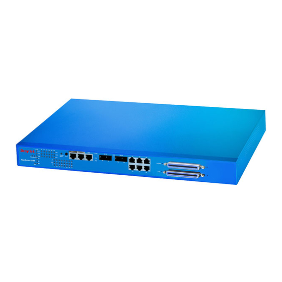
This chapter will introduce the system architecture, the definitions for master and slave devices, the LED indicators and connectors for preparing the installation listed in Chapter VigorAccess has one Master to subtend up to 6 Slaves. The hardware interface of Master unit covers alarm relay, console, management with RJ45, Gigabits optical interface with SC connector, GE subtend interface with RJ45 connector, ADSL2/+ with RJ21 connector, and POTS with RJ21 connector. - Page 18 VigorAccess Installation Guide Features supported by Master device module. Redundancy Optional uplink automatically switch of activity in the event of fiber failure. Inventory savings Common equipment across central office and outside plant deployments. Management Single IP Management. Packet filter and classification. Features supported by Slave device Management It is managed by VigorAccess master unit.
-
Page 19: Panel Of Master Device
All connections are made on the front panel of the VigorAccess (master device) except power connector. The connections on the front panel of the VigorAccess (master device) are shown below: Interface Description Factory Reset A reset button is used to reset system, and then IPDSLAM will operate by default configuration. -
Page 20: Master Led Indication
VigorAccess Installation Guide In addition, below shows the cables used in different connectors. Name Power Cord RJ45 Cable Serial Cable (Console) UPLINK Cable RJ45 Cable for MGN RJ45 Cable for G1 –G6 RJ-21 Cable for PHONE RJ-21 Cable for LINE The Master is consisted of two parts of features. - Page 21 Status Green 1000 Green Green Yellow Green DSLx Blinking Explanation The speed for Ethernet is 1000Mbps when LNK LED is on. The speed for Ethernet is 10/100Mbps when LNK LED is on. The Ethernet is in full duplex mode when LNK LED is on.
-
Page 22: Panel Of Slave Device
VigorAccess Installation Guide All connections are made on the front panel of the VigorAccess (slave device) except power connector. The connections on the front panel of the VigorAccess (slave device) are shown below: Interface Description Factory Reset A reset button is used to reset system, and then IPDSLAM will operate by default configuration. -
Page 23: Slave Led Indication
VigorAccess provides signal LED for CR (Critical), MS (Major Alarm), MN (Minor Alarm) and 24 ADSL ports. Status Green Green Green UP1 – UP2 Blinking Green Green Yellow Green DSL(1~24) Blinking Explanation The power LED is on when the power is applied. The power is not applied. -
Page 24: Installation And Connection
VigorAccess Installation Guide This section will guide you to install the VigorAccess through hardware connection To fully setup the VigorAccess connection, you have to finish the following items: Master rack-mounting installation Slave rack-mounting installation (optional) Interconnect master and salves (optional) Line interface connection (ADSL port connection) Phone interface connection Basically, a master device can offer complete services for the whole network. -
Page 25: Desktop Placement
VigorAccess Installation Guide Attach the brackets to the chassis in 19-, 23-inch rack. The second bracket attaches the other side of the chassis as above procedure. After bracket installation, VigorAccess chassis could be installed in the rack by using two screws for each side of rack. -
Page 26: Frame Ground Installation
VigorAccess Installation Guide The frame ground is on the rear side of the VigorAccess which is powered by AC connector. Connect the frame ground to a building’s earthing terminal by using frame ground wire. Importance: Please connect the frame ground first before you connect any other cables for this device. -
Page 27: Adsl Port Connection
The PSTN splitter should be connected to MDF on building. An MDF is usually placed in the building’s telephony room or wiring closet. MDF can terminate the outside telephone line into the building. In general, the LINE and PHONE interface on the Master device will connect to MDFs respectively and then to outside connection. -
Page 28: Scenario - Master Device Standalone
VigorAccess Installation Guide – – A master device can manage up to six slave devices. Certainly it can be used standalone without managing any slave device. In such condition, it can connect and control 24 ADSL CPE routers with DB-21 cable through MDF connection. In the above picture, the user of PC-3 wants to use phone and access the Internet at the same time;... -
Page 29: Scenario - Master And One Slave Devices
– – The following picture shows the sample connection between one Slave device and one Master device. Here we take PC-1, PC-2 and PC-3 as the examples that connecting to the Slave device directly and wanting to access the Internet through the Master device. In the above picture, the user of PC-3 wants to use phone and access the Internet at the same time;... -
Page 30: Scenario - Master And Six Slave Devices
VigorAccess Installation Guide – – The following picture shows the sample connection between six Slave devices and one Master device. Here we take PC-1, PC-2 and PC-3 as the examples that connecting to one Slave device directly and wanting to access the Internet through the Master device. In the above picture, the user of PC-3 wants to use phone and access the Internet at the same time;... -
Page 31: Scenario - Slave Device Standalone
– – A master device connects to Internet through UP-G connector. Yet, a slave device also can work alone without connecting the master device. For a standalone slave device, please use UP1or UP2 as the channel to access Internet with Ethernet cable. In the above picture, the user of PC-3 wants to use phone and access the Internet at the same time;... -
Page 32: Cpp (Centric Patch Panel)
VigorAccess Installation Guide The VigorAccess can provide ADSL and voice services over the same telephone wiring. It also has built in splitters internally that can save space and simplify installation. If the application is using on building environment, the CPP (Centric Patch Panel) is preferred. - Page 33 VigorAccess Installation Guide Phone service is available in VigorAccess. You can connect a RJ-11 jack port attached in a CPP to a telephone directly or applied in the same way shared in ADSL modem. The following example shows the connection for Data/Voice transmission through CPP.
-
Page 34: Power Connection
VigorAccess Installation Guide Before you purchasing the device, please check your environment to determine which power type that matches with your requirement. The AC input and ground connections can be done on the rear panel. You can connect the rack to ground by using spring screws. Connect the female end of the power cord to the power socket on the rear panel of VigorAccess. -
Page 35: Optical Fiber Connection
Warning: The above figure shows the DC power supply terminal block. It is the lugs at the wiring end from the power source. The wiring procedure is for ground-to-ground, positive-to-positive, and negative-to-negative in order. The ground wire should always be connected first and disconnected last. Before you start to do the optical fiber connection, please read the following warnings first. - Page 36 VigorAccess Installation Guide The trunk interface is made with the SC connector, which is available in two types: Long haul LX single-mode interface Short haul SX multi-mode interface For each type of optical transceiver, it should connect with corresponding optical fiber with proper mode.
-
Page 37: Console Port Connection
The default setting of the console port is “baud rate 9600, no parity, and 8 bit with 1 stop bit (N81)”. For the initial configuration, users need to use terminal emulator software on a computer and connect it to a network module through the console port. Users can connect the RJ-45 end of the console cable to the console port of the network module. - Page 38 VigorAccess Installation Guide Beware that the default login is “admin”, no password.
-
Page 39: Management Port Connection
Users can connect the RJ-45 cable to the Ethernet port of the computer. The IP address is 172.16.1.1 by default. The subnet of PC should be the same as default IP setting. Admin> network outband -------------------------------------------------------------------------------- OUTBAND INTF CONFIGURATION -------------------------------------------------------------------------------- IP Address NetMask Vlan Id... -
Page 40: Subtend Port Connection
VigorAccess Installation Guide Users can connect the uplink of IPDSLAM Slave to subtend interface of IPDSLAM Master by plug and play. Six slave devices are allowed to connect to master device at one time through G1 to G6 port on master device. The following graphic shows an example of possible subtend port connection To make the required configuration for master and slave devices, use CLI command. -
Page 41: Appendix: Connectors
Connections made with two 50-pin champ cables are attached to the RJ21 interface on VigorAccess. Each cable terminates with a 50-pin Telco straight champ connector. Pin 1 Pin 26 Pin assignments between the Line and the PSTN splitter. Wire Color TIP/RING Port Number White/blue... -
Page 42: Rs232 Connector
VigorAccess Installation Guide alarm relay connector also provides one set of contacts for audible alarms and one set for visual alarms. The maximum contact rating is 30VDC, 2A 125VDC, 0.5A. Pin8 The table below lists the pin assignments for backplane connector RJ45, the alarm relay connector. -
Page 43: Standard 10/100 Base-T Ethernet Interface Connector
No connection RJ45 jets provide 10/100 Base-T Ethernet interfaces. The interface supports MDI/MDIX auto-detection of either straight or crossover RJ45 cables. These cables are used on UP1,UP2/MGN interfaces. At 400 and 600 W the surface roughness was quite low (~15 2) and the coatings showed a mirror-like surface with a high brightness. - Page 44 VigorAccess Installation Guide RJ-45 Straight-through Cable Pin-outs (8P8C) Signal TP0+ TP0- TP1+ TP1- TP2+ TP2- TP3+ TP3- RJ-45 Crossover Cable Pin-outs (8P8C) Signal Signal TP0+ TP0+ TP0- TP0- TP1+ TP1+ TP1- TP1- TP2+ TP2+ TP2- TP2- TP3+ TP3+ TP3- TP3- Signal TP1+ TP1-...
-
Page 45: Contacting Your Dealer
VigorAccess Installation Guide If the device you have still cannot work correctly after trying many efforts, please contact your dealer for further help right away. For any questions, please feel free to send e-mail to support@draytek.com.