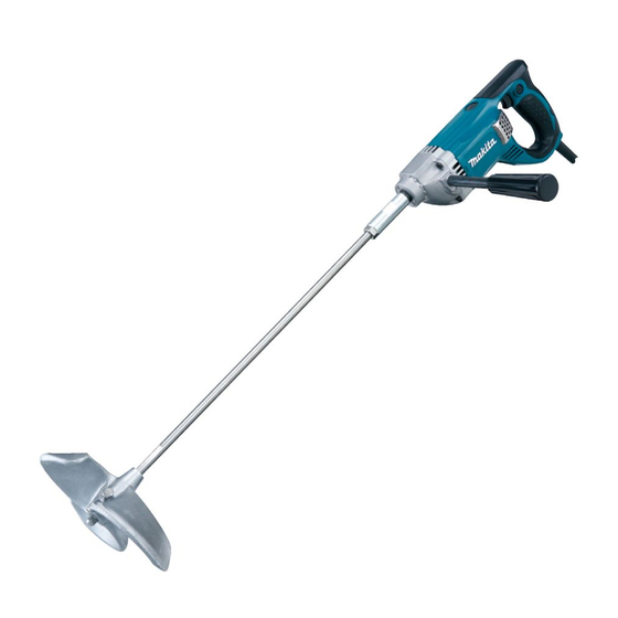
Makita UT2204 Technical Information
Hide thumbs
Also See for UT2204:
- Instruction manual (41 pages) ,
- Brochure (2 pages) ,
- Instruction manual (33 pages)
Advertisement
Quick Links
T
ECHNICAL INFORMATION
Model No.
Description
C
ONCEPT AND MAIN APPLICATIONS
Model UT2204 has been developed as the double insulation
model to the current grounding type model UT2203.
The main advantages are;
*Rear handle with soft rubber grip, ergonomically designed
for comfortable operation
*Pilot lamp
S
pecification
Voltage (V)
110
120
220
230
240
Max blade diameter: mm (")
No load speed: min-
Shank size of tool holder portion
Double insulation
Power supply cord: m (ft)
Net weight: kg (lbs)
S
tandard equipment
Wrench 13 ............ 1 pc
Wrench 19 ............ 2 pcs
Grip complete ....... 1 pc
Mixing blade 220 ........................ 1 pc
Shaft for Mixing blade 220 ......... 1 pc
Note: The standard equipment for the tool shown above may differ by country.
O
ptional accessories
Mixing blades 135, 175, 183, 190, 200, 201, 220
Shaft (for 135, 175, 183, 190, 200, 201, 220)
UT2204
Mixer
Cycle (Hz)
Current (A)
7.5
50/ 60
4.1
50/ 60
3.9
50/ 60
=rpm.
1
Europe: 4.0 (13.1), Other countries: 2.5 (8.2)
Continuous Rating (W)
Input
Output
850
440
850
480
850
480
220
550
M12
Yes
3.7 (8.2)
PRODUCT
P 1 / 7
L2
L1
W
Dimensions: mm (")
Length 1 (L1)
365 (14-3/8)
Length 2 (L2)
929 (36-1/2)
Width (W)
89 (3-1/2)
Height (H)
152 (6)
Length 1: without mixing blade
Length 2: with mixing blade
Max. Output (W)
850
900
900
H
Advertisement

Summary of Contents for Makita UT2204
- Page 1 Model No. UT2204 Description Mixer ONCEPT AND MAIN APPLICATIONS Model UT2204 has been developed as the double insulation model to the current grounding type model UT2203. The main advantages are; *Rear handle with soft rubber grip, ergonomically designed for comfortable operation *Pilot lamp Dimensions: mm (")
-
Page 2: Necessary Repairing Tools
Adjustable Bearing Retainer Wrench Removing Bearing retainer [2] LUBRICATION Put approx. 18g of Makita grease N No.1 in the gear room of Gear housing to protect parts and product from unusual abrasion. [3] DISASSEMBLY/ASSEMBLY [3] -1. Spindle and Gear Section DISASSEMBLING 1) Remove Shaft holder. - Page 3 P 3 / 7 epair [3] -1. Spindle and Gear Section (cont.) Fig. 5 ASSEMBLING 1) Put Ball bearing 626LLB in place into the bearing box portion Gear Housing of Gear housing. (Fig. 5) 2) Press-fit Spindle into Ball bearing 6202LLB using arbor press. Then assemble the Spindle to Gear housing.
- Page 4 P 4 / 7 High Voltage Countries and Areas where Noise Suppression is Required by Regulation ircuit diagram Fig. 10 Color index of lead wires' sheath Orange Black Clear White Insulated connecter Noise Heat-shrink tube Earth terminal suppressor Switch Support complete Choke coil Pilot lamp...
- Page 5 P 5 / 7 High Voltage Countries and Areas where Noise Suppression is Required by Regulation iring diagram [2] Motor Housing Put Earth terminal in place as illustrated in Fig. 12. Fig. 12 Earth terminal Polyolefin tube Motor housing viewed from Lead Wire (clear) Earth terminal Noise suppressor...
-
Page 6: Motor Housing
P 6 / 7 High Voltage Countries and Areas where Noise Suppression is Not Required ircuit diagram Fig. 14 Color index of lead wires' sheath Black Blue White Clear Insulated connecter Noise Heat-shrink tube Earth terminal suppressor* Switch Support complete Line filter** Pilot lamp Blue or White... - Page 7 P 7 / 7 High Voltage Countries and Areas where Noise Suppression is Not Required iring diagram [3] Handle Portion of Motor Housing Fig. 16 Be careful not to route the lead wires (black) Fix lead wire (clear) of Noise suppressor of Noise suppressor over the ribs.


