
Related Manuals for GE Vivid 3 Pro


Summary of Contents for GE Vivid 3 Pro
- Page 1 (217) 352-9330 | Click HERE Find the GE PC2IP IIB at our website:...
- Page 2 Technical Publication Part Number 2300164-100 Revision 7 GE Medical Systems Vivid™ 3 Pro/Vivid™ 3 Service Manual © Copyright 2006 by GE Medical Systems Artisan Technology Group - Quality Instrumentation ... Guaranteed | (888) 88-SOURCE | www.artisantg.com...
- Page 3 WURDE. • WIRD DIESE WARNUNG NICHT BEACHTET, SO KANN ES ZU VERLETZUNGEN DES KUNDENDIENSTTECHNIKERS, DES BEDIENERS ODER DES PATIENTEN DURCH ELEKTRISCHE SCHLÄGE, MECHANISCHE ODER SONSTIGE GEFAHREN KOMMEN. Artisan Technology Group - Quality Instrumentation ... Guaranteed | (888) 88-SOURCE | www.artisantg.com...
- Page 4 GE M EDICAL YSTEMS 2300164-100, R ™ 3 P ™ 3 S IRECTION EVISION IVID IVID ERVICE ANUAL • ESTE MANUAL DE SERVICIO SÓLO EXISTE EN INGLÉS. • SI ALGÚN PROVEEDOR DE SERVICIOS AJENO A GEMS SOLICITA UN IDIOMA QUE NO SEA EL INGLÉS, ES RESPONSABILIDAD DEL CLIENTE OFRECER UN SERVICIO DE TRADUCCIÓN.
- Page 5 GE M EDICAL YSTEMS 2300164-100, R ™ 3 P ™ 3 S IRECTION EVISION IVID IVID ERVICE ANUAL Artisan Technology Group - Quality Instrumentation ... Guaranteed | (888) 88-SOURCE | www.artisantg.com...
- Page 6 GE Medical Systems personnel. In performing all electrical work on these products, GE will use its own specially trained field engineers. All of GE’s electrical work on these products will comply with the requirements of the applicable electrical codes.
- Page 7 The contents of this publication may not be copied or duplicated in any form, in whole or in part, without prior written permission of GE Medical Systems. GE Medical Systems may revise this publication from time to time without written notice. TRADEMARKS All products and their name brands are trademarks of their respective holders.
- Page 8 GE M EDICAL YSTEMS 2300164-100, R ™ 3 P ™ 3 S IRECTION EVISION IVID IVID ERVICE ANUAL Revision History Revision Date Reason for change 2002 Initial Release April 2002 Second Release November 2002 Third Release September 2003 Fourth Release...
-
Page 9: Table Of Contents
GE M 2300164-100, R ™ 3 P ™ 3 S EDICAL YSTEMS IRECTION EVISION IVID IVID ERVICE ANUAL Table of Contents CHAPTER 1 Introduction Overview ............1 - 1 Purpose of Chapter 1 . - Page 10 GE M EDICAL YSTEMS 2300164-100, R ™ 3 P ™ 3 S IRECTION EVISION IVID IVID ERVICE ANUAL CHAPTER 2 Pre-Installation Overview ............2 - 1 Purpose of Chapter 2 .
- Page 11 GE M EDICAL YSTEMS 2300164-100, R ™ 3 P ™ 3 S IRECTION EVISION IVID IVID ERVICE ANUAL CHAPTER 3 Installation Overview............3 - 1 Purpose of Chapter 3 .
- Page 12 GE M EDICAL YSTEMS 2300164-100, R ™ 3 P ™ 3 S IRECTION EVISION IVID IVID ERVICE ANUAL VCR/ECG Tab ..........3 - 45 Technical Support Tab .
- Page 13 GE M EDICAL YSTEMS 2300164-100, R ™ 3 P ™ 3 S IRECTION EVISION IVID IVID ERVICE ANUAL CHAPTER 4 Functional Checks Overview............4 - 1 Purpose of Chapter 4 .
- Page 14 GE M EDICAL YSTEMS 2300164-100, R ™ 3 P ™ 3 S IRECTION EVISION IVID IVID ERVICE ANUAL CHAPTER 5 Components and Function (Theory) Overview ............5 - 1 Purpose of Chapter 5 .
- Page 15 GE M EDICAL YSTEMS 2300164-100, R ™ 3 P ™ 3 S IRECTION EVISION IVID IVID ERVICE ANUAL Introduction ..........5 - 41 Vivid™...
- Page 16 GE M EDICAL YSTEMS 2300164-100, R ™ 3 P ™ 3 S IRECTION EVISION IVID IVID ERVICE ANUAL CHAPTER 6 Service Adjustments Overview ............6 - 1 Purpose of Chapter 6 .
- Page 17 GE M EDICAL YSTEMS 2300164-100, R ™ 3 P ™ 3 S IRECTION EVISION IVID IVID ERVICE ANUAL CHAPTER 7 Diagnostics/Troubleshooting Overview............7 - 1 Purpose of Chapter .
- Page 18 GE M EDICAL YSTEMS 2300164-100, R ™ 3 P ™ 3 S IRECTION EVISION IVID IVID ERVICE ANUAL Calibration Page ..........7 - 109 Configuration Page .
- Page 19 GE M EDICAL YSTEMS 2300164-100, R ™ 3 P ™ 3 S IRECTION EVISION IVID IVID ERVICE ANUAL CHAPTER 8 Replacement Procedures Overview............8 - 1 Purpose of Chapter 8 .
- Page 20 GE M EDICAL YSTEMS 2300164-100, R ™ 3 P ™ 3 S IRECTION EVISION IVID IVID ERVICE ANUAL Back End Parts Replacement ......... 8 - 54 Preparation .
- Page 21 GE M EDICAL YSTEMS 2300164-100, R ™ 3 P ™ 3 S IRECTION EVISION IVID IVID ERVICE ANUAL HP 6540/3 USB Deskjet Color Printer Replacement Procedure for Vivid™ 3 BT03 Systems ........8 - 175...
- Page 22 GE M EDICAL YSTEMS 2300164-100, R ™ 3 P ™ 3 S IRECTION EVISION IVID IVID ERVICE ANUAL CHAPTER 9 Renewal Parts Overview ............9 - 1 Purpose of Chapter 9 .
- Page 23 GE M EDICAL YSTEMS 2300164-100, R ™ 3 P ™ 3 S IRECTION EVISION IVID IVID ERVICE ANUAL CHAPTER 10 Periodic Maintenance Overview............10 - 1 Purpose of Chapter 10 .
- Page 24 GE M EDICAL YSTEMS 2300164-100, R ™ 3 P ™ 3 S IRECTION EVISION IVID IVID ERVICE ANUAL Probe Current Leakage Test ........10 - 26 Excessive Current Leakage .
-
Page 25: Overview
GE M EDICAL YSTEMS 2300164-100, R ™ 3 P ™ 3 S IRECTION EVISION IVID IVID ERVICE ANUAL Chapter 1 Introduction Section 1-1 Overview 1-1-1 Purpose of Chapter 1 This chapter describes important issues related to safely servicing the Vivid™ 3 scanner. The service provider must read and understand all the information presented here before installing or servicing a unit. -
Page 26: Typical Users Of The Basic Service Manual
Provides periodic maintenance procedures for the Vivid™ 3 ultrasound unit. 1-1-3 Typical Users of the Basic Service Manual This manual is intended for the following categories of users: • GE service personnel (installation, maintenance, etc.). • Hospital service personnel. • Contractors (some parts of Chapter 2 - Pre-Installation). -
Page 27: Vivid™ 3 Models Covered In This Manual
GE M EDICAL YSTEMS 2300164-100, R ™ 3 P ™ 3 S IRECTION EVISION IVID IVID ERVICE ANUAL 1-1-4 Vivid™ 3 Models Covered in this Manual The Vivid™ 3 models documented in this manual are shown in Table 1-2 Table 1-3 below. - Page 28 GE M EDICAL YSTEMS 2300164-100, R ™ 3 P ™ 3 S IRECTION EVISION IVID IVID ERVICE ANUAL Table 1-3 Vivid™ 3 - BT03 - RFT Models Model Cat No. Description Comments BASE Vivid 3 Console Vivid 3 BT03 H45011ES...
-
Page 29: System History - Hardware And Software Versions
GE M EDICAL YSTEMS 2300164-100, R ™ 3 P ™ 3 S IRECTION EVISION IVID IVID ERVICE ANUAL 1-1-5 System History - Hardware and Software Versions The newest generation of the Vivid™ 3 (BT03) ultrasound unit is based on its predecessor, the Vivid™... -
Page 30: Important Conventions
GE M EDICAL YSTEMS 2300164-100, R ™ 3 P ™ 3 S IRECTION EVISION IVID IVID ERVICE ANUAL Section 1-2 Important Conventions 1-2-1 Conventions Used in this Manual 1-2-1-1 Model Designations This manual covers the Vivid™ 3 ultrasound units listed in... - Page 31 GE M EDICAL YSTEMS 2300164-100, R ™ 3 P ™ 3 S IRECTION EVISION IVID IVID ERVICE ANUAL 1-2-1-4 Standard Hazard Icons Important information will always be preceded by the exclamation point contained within a triangle, as seen throughout this chapter. In addition to text, several different graphical icons (symbols) may be used to make you aware of specific types of hazards that could cause harm.
-
Page 32: Safety Considerations
GE M EDICAL YSTEMS 2300164-100, R ™ 3 P ™ 3 S IRECTION EVISION IVID IVID ERVICE ANUAL Section 1-3 Safety Considerations 1-3-1 Introduction The following safety precautions must be observed during all phases of operation, service and repair of this equipment. -
Page 33: Electrical Safety
GE M EDICAL YSTEMS 2300164-100, R ™ 3 P ™ 3 S IRECTION EVISION IVID IVID ERVICE ANUAL WARNING: Equipment damage could result if special care is not taken when transporting the system in a vehicle. ALWAYS: • Secure the system in an upright position and lock the wheels (brake). -
Page 34: Dangerous Procedure Warnings
GE M EDICAL YSTEMS 2300164-100, R ™ 3 P ™ 3 S IRECTION EVISION IVID IVID ERVICE ANUAL 1-3-5 Dangerous Procedure Warnings Warnings, such as the examples below, precede potentially dangerous procedures throughout this manual. Instructions contained in the warnings must be followed. -
Page 35: Product Labels And Icons
GE M EDICAL YSTEMS 2300164-100, R ™ 3 P ™ 3 S IRECTION EVISION IVID IVID ERVICE ANUAL Section 1-4 Product Labels and Icons The Vivid™ 3 ultrasound unit comes equipped with product labels and icons. These labels and icons represent pertinent information regarding the operation of the ultrasound unit. - Page 36 GE M EDICAL YSTEMS 2300164-100, R ™ 3 P ™ 3 S IRECTION EVISION IVID IVID ERVICE ANUAL Figure 1-2 Product Label and Icon Locations (Rear) Main Label AC Voltage Rating Label GND Label 1-12 Section 1-4 - Product Labels and Icons...
-
Page 37: Label Descriptions
GE M EDICAL YSTEMS 2300164-100, R ™ 3 P ™ 3 S IRECTION EVISION IVID IVID ERVICE ANUAL 1-4-2 Label Descriptions The following table shows the labels and symbols that may be found on the Vivid™ 3 ultrasound unit, and provides a description of each label’s purpose and location. - Page 38 GE M EDICAL YSTEMS 2300164-100, R ™ 3 P ™ 3 S IRECTION EVISION IVID IVID ERVICE ANUAL Table 1-7 Product Icons (Continued) Label Name Description Location "DANGER - Risk of explosion The system is not designed for use with Indicated in the Service Manual.
-
Page 39: Vivid™ 3 External Labels
GE M EDICAL YSTEMS 2300164-100, R ™ 3 P ™ 3 S IRECTION EVISION IVID IVID ERVICE ANUAL 1-4-3 Vivid™ 3 External Labels In addition to the labels described in the previous section, additional labels may be found on the Vivid™... - Page 40 GE M EDICAL YSTEMS 2300164-100, R ™ 3 P ™ 3 S IRECTION EVISION IVID IVID ERVICE ANUAL • German: Used in all German language countries. Figure 1-5 Main Label (German) • French: Used in all French language countries. Figure 1-6 Main Label (French)
- Page 41 GE M EDICAL YSTEMS 2300164-100, R ™ 3 P ™ 3 S IRECTION EVISION IVID IVID ERVICE ANUAL • Spanish: Used in all Spanish language countries. Figure 1-7 Main Label (Spanish) • Portuguese: Used in all Portuguese language countries. Figure 1-8 Main Label (Portuguese)
- Page 42 GE M EDICAL YSTEMS 2300164-100, R ™ 3 P ™ 3 S IRECTION EVISION IVID IVID ERVICE ANUAL Figure 1-9 Main Label (Portuguese) 220 - 240V • Italian: Used in all Italian language countries. Figure 1-10 Main Label (Italian) 1-18 Section 1-4 - Product Labels and Icons Artisan Technology Group - Quality Instrumentation ...
- Page 43 GE M EDICAL YSTEMS 2300164-100, R ™ 3 P ™ 3 S IRECTION EVISION IVID IVID ERVICE ANUAL • Chinese: Used in all Chinese language countries. Figure 1-11 Main Label (Chinese) • Danish: Used in all Danish language countries. Figure 1-12 Main Label (Danish)
- Page 44 GE M EDICAL YSTEMS 2300164-100, R ™ 3 P ™ 3 S IRECTION EVISION IVID IVID ERVICE ANUAL • Dutch: Used in all Dutch language countries. Figure 1-13 Main Label (Dutch) • Finnish: Used in all Finnish language countries. Figure 1-14 Main Label (Finnish)
- Page 45 GE M EDICAL YSTEMS 2300164-100, R ™ 3 P ™ 3 S IRECTION EVISION IVID IVID ERVICE ANUAL • Greek: Used in all Greek language countries. Figure 1-15 Main Label (Greek) • Japanese: Used in all Japanese language countries. Figure 1-16 Main Label (Japanese)
- Page 46 GE M EDICAL YSTEMS 2300164-100, R ™ 3 P ™ 3 S IRECTION EVISION IVID IVID ERVICE ANUAL • Norwegian: Used in all Norwegian language countries. Figure 1-17 Main Label (Norwegian) • Russian: Used in all Russian language countries. Figure 1-18 Main Label (Russian)
- Page 47 GE M EDICAL YSTEMS 2300164-100, R ™ 3 P ™ 3 S IRECTION EVISION IVID IVID ERVICE ANUAL • Swedish: Used in all Swedish language countries. Figure 1-19 Main Label (Swedish) 1-4-3-2 Rating Labels Indicates the ultrasound unit’s factory preset input AC voltage as follows: •...
- Page 48 GE M EDICAL YSTEMS 2300164-100, R ™ 3 P ™ 3 S IRECTION EVISION IVID IVID ERVICE ANUAL 1-4-3-3 GND Label Indicates the protective earth (grounding) terminal. The GND label shown below is located at the rear of the unit, as shown in Figure 1-2 on page 1-12.
-
Page 49: Emc, Emi, And Esd
GE M EDICAL YSTEMS 2300164-100, R ™ 3 P ™ 3 S IRECTION EVISION IVID IVID ERVICE ANUAL Section 1-5 EMC, EMI, and ESD 1-5-1 Electromagnetic Compatibility (EMC) Electromagnetic compatibility describes a level of performance of a device within its electromagnetic environment. -
Page 50: Standards Used
GE M EDICAL YSTEMS 2300164-100, R ™ 3 P ™ 3 S IRECTION EVISION IVID IVID ERVICE ANUAL 1-5-3 Standards Used To fulfill the requirements of relevant EC directives and/or European Harmonized/International standards, the following documents/standards have been used: Table 1-8... -
Page 51: Customer Assistance
Milwaukee, WI 53219 Customer Answer Center Phone: +1-262-524-5698 Fax: +1-414-647-4125 Europe General Imaging: +49 (212) 2802 207 GE Ultraschall Deutschland GmbH& Co. KG Cardiac: +49 (212) 2802 208 BeethovenstraBe 239 Postfach 11 05 60, D-42665 Solingen Germany Fax: +49 212 2802 431... -
Page 52: Purpose Of Chapter 2
GE M EDICAL YSTEMS 2300164-100, R ™ 3 P ™ 3 S IRECTION EVISION IVID IVID ERVICE ANUAL Chapter 2 Pre-Installation Section 2-1 Overview 2-1-1 Purpose of Chapter 2 This chapter provides the information required to plan and prepare for the installation of a Vivid™ 3 ultrasound unit. -
Page 53: Console Requirements
GE M EDICAL YSTEMS 2300164-100, R ™ 3 P ™ 3 S IRECTION EVISION IVID IVID ERVICE ANUAL Section 2-2 Console Requirements 2-2-1 Unit Environmental Requirements Table 2-2 Environmental Requirements Relative Humidity Requirement Temperature (non-condensing) Air Pressure Operational 50 — 70% 700 —... -
Page 54: Electrical Requirements
2-2-5 Electrical Requirements NOTE: GE Medical Systems requires a dedicated power and Ground for the proper operation of its Ultrasound equipment. This dedicated power shall originate at the last distribution panel before the system. Sites with a mains power system with defined Neutral and Live: The dedicated line shall consist of one phase, a neutral (not shared with any other circuit), and a full size Ground wire from the distribution panel to the Ultrasound outlet. - Page 55 2-2-5-5 Mains Power Plug If the unit arrives without a power plug, or with the wrong plug, contact your GE dealer. When necessary, the installation engineer will supply the locally-required power plug. 2-2-5-6...
-
Page 56: Emi Limitations
GE M EDICAL YSTEMS 2300164-100, R ™ 3 P ™ 3 S IRECTION EVISION IVID IVID ERVICE ANUAL 2-2-6 EMI Limitations Ultrasound machines are susceptible to Electromagnetic Interference (EMI) from radio frequencies, magnetic fields, and transients in the air or wiring. They also generate EMI. The Vivid™ 3 ultrasound unit complies with limits as stated on the EMC label. -
Page 57: Probe Environmental Requirements
RF gaskets touch metal. a different, appropriate location. The interconnect cables are grounded and require ferrite beads and other shielding. Use GE specified harnesses Cable length, material, and routing are all important; do not make any changes that do and peripherals. -
Page 58: Facility Needs
(and the accompanying electrical installations) are highly sophisticated and special engineering competence is required. All electrical work on these products must comply with the requirements of applicable electrical codes. The purchaser of GE equipment must utilize only qualified personnel to perform electrical servicing of the equipment. -
Page 59: Mandatory Site Requirements
2-11 for network details that are required. Note: All relevant preliminary network outlets installations at the prepared site must be performed by authorized contractors. The purchaser of GE equipment must utilize only qualified personnel to perform servicing of the equipment. 2-3-3 Site Recommendations The following are (optional) site recommendations. -
Page 60: Networking Pre-Installation Requirements
Recommended Ultrasound Room Layout VIVID 3 Dedicated Power Outlets Hospital Network Dedicated Analog Telephone Line for Connection to InSite GE Cabinet for Software and Manuals (optional) 36 IN. (92 CM) Scale: Each square = 1 sq ft (144 sq ins) Figure 2-1 Minimal Floor Plan 2.5m x 3m (8.2ft x 9.84 ft) - Page 61 GE M EDICAL YSTEMS 2300164-100, R ™ 3 P ™ 3 S IRECTION EVISION IVID IVID ERVICE ANUAL 2-3-4-4 DICOM Option Pre-Installation Requirements To configure the Vivid™ 3 ultrasound unit to work with other network connections, the network administrator must provide the required information, which should include the following: •...
-
Page 62: Connectivity Installation Worksheet
GE M EDICAL YSTEMS 2300164-100, R ™ 3 P ™ 3 S IRECTION EVISION IVID IVID ERVICE ANUAL Section 2-4 Connectivity Installation Worksheet Site System Information Comments: Floor: Site: Dept: Room: Type: Vivid™ 3 SN: REV: CONTACT INFORMATION Name Title... - Page 63 GE M EDICAL YSTEMS 2300164-100, R ™ 3 P ™ 3 S IRECTION EVISION IVID IVID ERVICE ANUAL Table 2-6 Pre-Installation Check List Action Schedule at least 3 hours for installation of the system. Notify installation team of the existence of any variances from the basic installation.
-
Page 64: Purpose Of Chapter 3
GE M EDICAL YSTEMS 2300164-100, R ™ 3 P ™ 3 S IRECTION EVISION IVID IVID ERVICE ANUAL Chapter 3 Installation Section 3-1 Overview 3-1-1 Purpose of Chapter 3 This chapter provides instructions for installing the Vivid™ 3 ultrasound unit. Before beginning the installation process, an appropriate site must be prepared, as described in Chapter 2 - Pre-Installation. -
Page 65: Installation Reminders
GE M EDICAL YSTEMS 2300164-100, R ™ 3 P ™ 3 S IRECTION EVISION IVID IVID ERVICE ANUAL Section 3-2 Installation Reminders 3-2-1 Average Installation Time Once the site has been prepared, the average installation time required is shown in Table 3-2 below. -
Page 66: Safety Reminders
GE M EDICAL YSTEMS 2300164-100, R ™ 3 P ™ 3 S IRECTION EVISION IVID IVID ERVICE ANUAL 3-2-3 Safety Reminders WHEN USING ANY TEST INSTRUMENT THAT IS CAPABLE OF DANGER: OPENING THE AC GROUND LINE (I.E., METER’S GROUND SWITCH IS OPEN), DO NOT TOUCH THE UNIT! WARNING: Two people are required to unpack the unit, as it is heavy. -
Page 67: Receiving And Unpacking The Equipment
GE M EDICAL YSTEMS 2300164-100, R ™ 3 P ™ 3 S IRECTION EVISION IVID IVID ERVICE ANUAL Section 3-3 Receiving and Unpacking the Equipment CAUTION: Please read this section fully before unpacking the Vivid™ 3 ultrasound unit. Note: The Vivid™ 3 ultrasound unit is shipped from the factory either in a wooden shipping crate, or in a cardboard shipping carton. - Page 68 If the crate is damaged, or if either the Drop or Tilt indicators have turned red (showing failure), please inform the GE Medical Systems sales representative immediately. In addition, mark on the shipping consignment note or packing slip/post-delivery checklist (in the “Package” column) that the Tilt and/or Drop indicators show failure.
- Page 69 GE M EDICAL YSTEMS 2300164-100, R ™ 3 P ™ 3 S IRECTION EVISION IVID IVID ERVICE ANUAL CAUTION: When using sharp tools to open packing materials, take care to avoid cutting or damaging the contents. Note: Unless otherwise specified, referenced items are shown in Figure 3-1 on page 3-4.
- Page 70 GE M EDICAL YSTEMS 2300164-100, R ™ 3 P ™ 3 S IRECTION EVISION IVID IVID ERVICE ANUAL 12) Remove the two monitor foam supports (item 12 in Figure 3-4), located one on each side of the monitor. Figure 3-4 Antistatic Cover, Supports and Accessories...
- Page 71 GE M EDICAL YSTEMS 2300164-100, R ™ 3 P ™ 3 S IRECTION EVISION IVID IVID ERVICE ANUAL 17) Press the brake pedal, located near the bottom of the front of the unit, to the right, to prevent the wheels from swiveling, as described in the Swivel Brake Label section, page 1-24.
-
Page 72: Unpacking The Cardboard Shipping Carton
If the crate is damaged, or if either the Drop or Tilt indicators have turned red (showing failure), please inform the GE Medical Systems sales representative immediately. In addition, mark on the shipping consignment note or packing slip/post-delivery checklist (in the “Package” column) that the Tilt and/or Drop indicators show failure. - Page 73 GE M EDICAL YSTEMS 2300164-100, R ™ 3 P ™ 3 S IRECTION EVISION IVID IVID ERVICE ANUAL CAUTION: When using sharp tools to open packing materials, take care to avoid cutting or damaging the contents. Note: Unless otherwise specified, referenced items are shown in Figure 3-6 on page 3-9.
- Page 74 GE M EDICAL YSTEMS 2300164-100, R ™ 3 P ™ 3 S IRECTION EVISION IVID IVID ERVICE ANUAL Figure 3-8 Front and Side View of the Unit in the Shipping Carton 8) Pull out and remove the monitor support (item 10 in...
- Page 75 GE M EDICAL YSTEMS 2300164-100, R ™ 3 P ™ 3 S IRECTION EVISION IVID IVID ERVICE ANUAL 9) Release the front stopper (item C in Figure 3-10 below) by sliding the metal sleeve located at the locking pin’s base upwards, and then turning it towards you.
-
Page 76: Preparing For Installation
When preparing for installation of a Vivid™ 3 system, it is important to verify that all items ordered by the customer have been received. Compare all items listed on the packing slip (shipping consignment note) with those received and report any items that are missing, back-ordered, or damaged, to your GE Medical Systems sales representative. -
Page 77: Component Inspection
3-4-3-1 Damage Inspection Checklist Visually inspect the contents of the shipping crate/shipping carton for damage. If any parts are damaged or missing, contact an authorized GE Service Representative. A Damage Inspection Checklist is provided in Table 3-6 on page 3-15. - Page 78 GE M EDICAL YSTEMS 2300164-100, R ™ 3 P ™ 3 S IRECTION EVISION IVID IVID ERVICE ANUAL Table 3-6 Damage Inspection Checklist Step Item Recommended Procedure Verify that the system is switched OFF and unplugged. Clean the console and Console control panel.
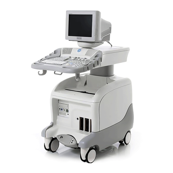
- Page 79 GE M EDICAL YSTEMS 2300164-100, R ™ 3 P ™ 3 S IRECTION EVISION IVID IVID ERVICE ANUAL 3-4-3-2 Front and Side View of the Vivid™ 3 Ultrasound Unit Figure 3-11 below shows the Vivid™ 3 ultrasound unit components that are visible from the front and side of the ultrasound unit.
- Page 80 GE M EDICAL YSTEMS 2300164-100, R ™ 3 P ™ 3 S IRECTION EVISION IVID IVID ERVICE ANUAL Foot Brake: Three-position brake, as follows: • LEFT (P) locks the wheels. • MIDDLE unlocks the wheels. • RIGHT (double arrows) locks the swivel action.
- Page 81 GE M EDICAL YSTEMS 2300164-100, R ™ 3 P ™ 3 S IRECTION EVISION IVID IVID ERVICE ANUAL 3-4-3-3 Rear View of the Vivid™ 3 Ultrasound Unit The following figure shows the Vivid™ 3 ultrasound unit components that are visible from the rear of the ultrasound unit: Figure 3-12 Rear View of the Vivid™...
-
Page 82: System Voltage Confirmation
Figure 3-28 on page 3-47). 5) Click OK. Note: If the voltage is not set correctly, contact an authorized GE Service Representative. Chapter 3 - Installation 3-19 Artisan Technology Group - Quality Instrumentation ... Guaranteed | (888) 88-SOURCE | www.artisantg.com... -
Page 83: Video Formats Confirmation
PAL. 5) Click OK. Note: If the video format is not set correctly, contact an authorized GE Service Representative. 3-20 Section 3-4 - Preparing for Installation Artisan Technology Group - Quality Instrumentation ... Guaranteed | (888) 88-SOURCE | www.artisantg.com... -
Page 84: Ensuring Protection From Emi
RF gaskets touch metal. appropriate location. The interconnect cables are grounded and require ferrite beads and other shielding. Cable Use GE specified harnesses length, material, and routing are all important; do not make any changes that do not meet and peripherals. -
Page 85: Completing The Hardware Installation
GE M EDICAL YSTEMS 2300164-100, R ™ 3 P ™ 3 S IRECTION EVISION IVID IVID ERVICE ANUAL Section 3-5 Completing the Hardware Installation It is recommended to pay attention to the system specifications and make sure the facility has been prepared in accordance with the information provided in Chapter 2 - Pre-Installation. -
Page 86: Connecting Peripherals
GE M EDICAL YSTEMS 2300164-100, R ™ 3 P ™ 3 S IRECTION EVISION IVID IVID ERVICE ANUAL 3-5-2 Connecting Peripherals Peripheral devices, such as a VCR or printer, are connected to the Vivid™ 3 ultrasound unit using the rear panel connectors. Ensure that all peripheral devices connected to the ultrasound unit comply with national safety requirements for medical equipment, including IEC601, CSA22.2, AS3200.1 and UL544. - Page 87 For use with external peripherals. Voltages are set according to local country voltage. If additional auxiliary outlets are required, use the special cable 2. AUXILIARY AC OUTLET provided by GE. DO NOT attempt to connect additional peripherals using an external wall outlet. 3. THERMAL CIRCUIT BREAKERS Three 4A thermal circuit breakers for fuse protection.
- Page 88 GE M EDICAL YSTEMS 2300164-100, R ™ 3 P ™ 3 S IRECTION EVISION IVID IVID ERVICE ANUAL 3-5-2-1-2 Left Rear Panel Connectors Table 3-10 describes the connectors included in the left rear panel (shown in Figure 3-16): Figure 3-16 Left Rear Panel Connectors...
- Page 89 GE M EDICAL YSTEMS 2300164-100, R ™ 3 P ™ 3 S IRECTION EVISION IVID IVID ERVICE ANUAL 3-5-2-2 Connecting the VCR 1) Place the VCR on the peripheral tray and connect the following: Table 3-11 VCR Cables From the VCR...
- Page 90 GE M EDICAL YSTEMS 2300164-100, R ™ 3 P ™ 3 S IRECTION EVISION IVID IVID ERVICE ANUAL Table 3-13 Color Printer Cables To the Cables From the Color Printer underneath the Control Console Video IN Composite/Video OUT 1 External Trigger...
-
Page 91: Connecting Probes
GE M EDICAL YSTEMS 2300164-100, R ™ 3 P ™ 3 S IRECTION EVISION IVID IVID ERVICE ANUAL 3-5-3 Connecting Probes The Vivid™ 3 ultrasound unit operates with various types of probes that are used for scanning patients, including flat phased, convex and linear electronic array probes. Once connected, the probes can be selected for different applications. -
Page 92: Connecting The Ecg
GE M EDICAL YSTEMS 2300164-100, R ™ 3 P ™ 3 S IRECTION EVISION IVID IVID ERVICE ANUAL 3-5-4 Connecting the ECG The internal ECG is connected into a rectangular-shaped socket on the patient trace (I/O) panel. The patient trace (I/O) panel is located on the front of the ultrasound unit, as shown in Figure 3-11 on page 3-16. - Page 93 GE M EDICAL YSTEMS 2300164-100, R ™ 3 P ™ 3 S IRECTION EVISION IVID IVID ERVICE ANUAL AHA (Americas, Japan) IEC (Europe, Asia, ROW) Figure 3-18 ECG Cable and Electrode Placement Note: For optimal ECG operation, use only electrodes that meet universal standards - see Table 3-16.
-
Page 94: Connecting The Unit To A Power Source
GE Medical Systems. Use only the power cords, cables and plugs provided by or designated by GE Medical Systems to connect the unit to the power source. CAUTION: Verify compliance with all electrical and safety requirements and check the power cord to verify that it is intact and of hospital-grade before connecting the unit to the power source. - Page 95 GE M EDICAL YSTEMS 2300164-100, R ™ 3 P ™ 3 S IRECTION EVISION IVID IVID ERVICE ANUAL 3-5-5-2 Connecting the Ultrasound Unit to the Electrical Outlet Note: To help assure grounding reliability, connect to a hospital-grade or “hospital only” grounded power outlet.
-
Page 96: Switching The System On/Off
GE M EDICAL YSTEMS 2300164-100, R ™ 3 P ™ 3 S IRECTION EVISION IVID IVID ERVICE ANUAL 3-5-5-3 Disconnecting the Ultrasound Unit from the Electrical Outlet CAUTION: Whenever disconnecting the Vivid™ 3 unit from the electrical outlet, always observe the safety precautions. - Page 97 GE M EDICAL YSTEMS 2300164-100, R ™ 3 P ™ 3 S IRECTION EVISION IVID IVID ERVICE ANUAL Figure 3-20 Shut-Down Options Screen 3-34 Section 3-5 - Completing the Hardware Installation Artisan Technology Group - Quality Instrumentation ... Guaranteed | (888) 88-SOURCE | www.artisantg.com...
-
Page 98: System Configuration
GE M EDICAL YSTEMS 2300164-100, R ™ 3 P ™ 3 S IRECTION EVISION IVID IVID ERVICE ANUAL Section 3-6 System Configuration Once all the required peripherals have been installed and the unit has been switched on, configure the system settings in the System Configuration window tabs. Refer to the Vivid™ 3 Pro/Vivid™ 3 Expert User Manual for additional information about system configuration. -
Page 99: System Tab
GE M EDICAL YSTEMS 2300164-100, R ™ 3 P ™ 3 S IRECTION EVISION IVID IVID ERVICE ANUAL 3-6-3 System Tab 1) Press Config on the alphanumeric keyboard. The System Configuration window is displayed. 2) Trackball to the System tab and press Select. The software information is displayed in the upper... -
Page 100: Connectivity Tab
GE M EDICAL YSTEMS 2300164-100, R ™ 3 P ™ 3 S IRECTION EVISION IVID IVID ERVICE ANUAL 3-6-4 Connectivity Tab For details on the Connectivity tab, refer to the Connectivity Setup section, on page 3-50. 3-6-5 Archive Tab 1) Press Config on the alphanumeric keyboard. The System Configuration window is displayed. - Page 101 GE M EDICAL YSTEMS 2300164-100, R ™ 3 P ™ 3 S IRECTION EVISION IVID IVID ERVICE ANUAL 7) Select the patient ID page type from the Patient ID Page Type dropdown list, as follows: • Type A: displays patient ID, last and first name, weight, height, BSA, BP and other fields.
-
Page 102: Annotation Settings Tab
GE M EDICAL YSTEMS 2300164-100, R ™ 3 P ™ 3 S IRECTION EVISION IVID IVID ERVICE ANUAL 3-6-6 Annotation Settings Tab 1) Press Config on the alphanumeric keyboard. The System Configuration window is displayed. 2) Trackball to the Annotation Settings tab and press Select. The Annotation Settings tab is... - Page 103 GE M EDICAL YSTEMS 2300164-100, R ™ 3 P ™ 3 S IRECTION EVISION IVID IVID ERVICE ANUAL Whenever the Bodymark is now displayed, it will appear in the newly-selected position (until such time as this setting is changed) 5.) Activate the Duplicate Bodymark on Switch Window and/or the Bodymark Menu on Freeze checkboxes, as required.
-
Page 104: System Options Tab
Note: Please note that all passwords should be visible underneath the control console or/and on the green password (option) certificate. If a new password (option) is required, contact the GE representative to initiate the appropriate process, so that the relevant password (option) will be installed on the system. - Page 105 GE M EDICAL YSTEMS 2300164-100, R ™ 3 P ™ 3 S IRECTION EVISION IVID IVID ERVICE ANUAL Note: If an option was not initially purchased or installed, it may be acquired and/or installed later. During option installation, type the relevant password in the appropriate Option window (see...
-
Page 106: Printers Tab
Note: Please note, the printers indicated in the Currently Installed Printers field, are the recommended and approved printers to be used with the Vivid™ 3 system. Other generic printers are not approved, and GE Medical Systems will not guarantee their correct operation on this system. - Page 107 GE M EDICAL YSTEMS 2300164-100, R ™ 3 P ™ 3 S IRECTION EVISION IVID IVID ERVICE ANUAL 6) Trackball to the Print B combo box, choose the required printer and press Select. (In this example, Color Printer is selected).
-
Page 108: Vcr/Ecg Tab
GE M EDICAL YSTEMS 2300164-100, R ™ 3 P ™ 3 S IRECTION EVISION IVID IVID ERVICE ANUAL 3-6-9 VCR/ECG Tab 1) Press Config on the alphanumeric keyboard. The System Configuration window is displayed. 2) Trackball to the VCR/ECG tab and press Select. The VCR/ECG tab is displayed, as shown below:... - Page 109 GE M EDICAL YSTEMS 2300164-100, R ™ 3 P ™ 3 S IRECTION EVISION IVID IVID ERVICE ANUAL 5) In the ECG and Phono Options area, complete the following, as required: • Select each connected option including, ECG Exist, ECG External, Phono Exist and/or Phono Filter.
-
Page 110: Technical Support Tab
GE M EDICAL YSTEMS 2300164-100, R ™ 3 P ™ 3 S IRECTION EVISION IVID IVID ERVICE ANUAL 3-6-10 Technical Support Tab The System Configuration Technical Support tab is used when new hardware has been installed, or when it necessary to enable new functionality. The appearance of the Technical Support tab differs in accordance with the specific Vivid™... - Page 111 GE M EDICAL YSTEMS 2300164-100, R ™ 3 P ™ 3 S IRECTION EVISION IVID IVID ERVICE ANUAL Table 3-17 Recommended Vivid™ 3 Hardware Configurations - RFI Models Item BT03 Vivid™ 3 Second Re Image Port No board Front Board...
-
Page 112: Technical Support History Tab
GE M EDICAL YSTEMS 2300164-100, R ™ 3 P ™ 3 S IRECTION EVISION IVID IVID ERVICE ANUAL 3-6-11 Technical Support History Tab The Technical Support History is where you would record any historical technical support information that may be relevant to a problem, or any other maintenance operations performed. -
Page 113: Connectivity Setup
GE M EDICAL YSTEMS 2300164-100, R ™ 3 P ™ 3 S IRECTION EVISION IVID IVID ERVICE ANUAL Section 3-7 Connectivity Setup 3-7-1 Introduction The Vivid™ 3 ultrasound unit can be connected to various connectivity devices, such as DICOM devices and EchoPac servers. The following sections describe how to connect the system to a remote archive/work station or a DICOM service, using a TCP/IP connection. - Page 114 GE M EDICAL YSTEMS 2300164-100, R ™ 3 P ™ 3 S IRECTION EVISION IVID IVID ERVICE ANUAL 3-7-2-2 Local Network Connection to EchoPAC PC Workstation Do not use the fifth connector and the switch can be in any position,...
-
Page 115: Setting Up For Connectivity
EchoPAC. This function (which is configured on EchoPAC, not on the Vivid™ 3 system) is used to export examination results to the Hospital Information System (HIS), through HL7 protocol. Users requiring this option should contact the GE representative. 1) Press Config on the alphanumeric keyboard. The System Configuration window is displayed. - Page 116 GE M EDICAL YSTEMS 2300164-100, R ™ 3 P ™ 3 S IRECTION EVISION IVID IVID ERVICE ANUAL 3) Verify that the following options are installed, as required: • DICOM Media Creator is required to support DICOM storage to MOD or CD-R media.
- Page 117 GE M EDICAL YSTEMS 2300164-100, R ™ 3 P ™ 3 S IRECTION EVISION IVID IVID ERVICE ANUAL Figure 3-35 Setting up Remote Server for MPEGvue 6) When done, trackball to the OK button and press Select. 7) Trackball to the OK button and press Select.
-
Page 118: Setting Up The Network Connection
GE M EDICAL YSTEMS 2300164-100, R ™ 3 P ™ 3 S IRECTION EVISION IVID IVID ERVICE ANUAL 3-7-4 Setting Up the Network Connection 1) Press Config on the alphanumeric keyboard. The System Configuration window is displayed. 2) Trackball to the Connectivity tab and press Select. The Connectivity tab is displayed, with the... - Page 119 GE M EDICAL YSTEMS 2300164-100, R ™ 3 P ™ 3 S IRECTION EVISION IVID IVID ERVICE ANUAL 5) Trackball to the Local Settings tab and press Select. The Local Settings tab is displayed, as shown below. Figure 3-38 Local Settings Tab Note: The Computer Name field shows the serial number of your Vivid™...
-
Page 120: Setting Up For Communication With A Prosolv Workstation
GE M EDICAL YSTEMS 2300164-100, R ™ 3 P ™ 3 S IRECTION EVISION IVID IVID ERVICE ANUAL 3-7-5 Setting Up for Communication with a Prosolv Workstation The Vivid™ 3 ultrasound unit can connect to a Prosolv DICOM viewer through a DICOM server. The unit cannot connect directly to the viewer. - Page 121 GE M EDICAL YSTEMS 2300164-100, R ™ 3 P ™ 3 S IRECTION EVISION IVID IVID ERVICE ANUAL 8) Enter the IP address for the DICOM server in the IP-address field. 9) Trackball to the Dicom Storage Server line in the Services table. The Services tab is expanded,...
- Page 122 GE M EDICAL YSTEMS 2300164-100, R ™ 3 P ™ 3 S IRECTION EVISION IVID IVID ERVICE ANUAL Figure 3-42 Connectivity Tab (Services for DICOM Print Expanded) 12) Under Settings, select the required Format, Film Orientation, etc. 13.)Proceed to the next section, to perform the procedure for validating communication with the DICOM server.
- Page 123 GE M EDICAL YSTEMS 2300164-100, R ™ 3 P ™ 3 S IRECTION EVISION IVID IVID ERVICE ANUAL 3-7-5-1 Validating Communication with the DICOM Server 1) Trackball to the Views tab and press Select. The Views tab is displayed. 2) Trackball to the Dataflow button and press Select. The full list of data flows is displayed:...
- Page 124 GE M EDICAL YSTEMS 2300164-100, R ™ 3 P ™ 3 S IRECTION EVISION IVID IVID ERVICE ANUAL 5) If the connection was successfully established, trackball to the Dicom Storage Server line and press Select, then trackball to the Check button and press Select.
- Page 125 GE M EDICAL YSTEMS 2300164-100, R ™ 3 P ™ 3 S IRECTION EVISION IVID IVID ERVICE ANUAL 3-7-5-2 Validating Communication with the Workstation 1) Press the Archive button on the control panel. The Patient List window is displayed, as shown below: Figure 3-44 Patient List Window 2) Select the Local Archive-Int.
-
Page 126: Connecting Directly To Echopac
GE M EDICAL YSTEMS 2300164-100, R ™ 3 P ™ 3 S IRECTION EVISION IVID IVID ERVICE ANUAL 5) Press <Ctrl+S> to view the status of the spooler, as shown below: Figure 3-45 Job Spooler The Status column can contain the following options: •... - Page 127 GE M EDICAL YSTEMS 2300164-100, R ™ 3 P ™ 3 S IRECTION EVISION IVID IVID ERVICE ANUAL 7) Select the EchoPAC server from the Name dropdown list. The Services tab is updated, as shown below: Figure 3-46 Services Tab - EchoPAC 8) Enter the IP address of the EchoPAC server in the IP-address field.
- Page 128 GE M EDICAL YSTEMS 2300164-100, R ™ 3 P ™ 3 S IRECTION EVISION IVID IVID ERVICE ANUAL 10) If EchoPAC Network is required, make sure that the EchoPAC Network checkbox is selected, as shown in Figure 3-47, above, then proceed as follows: a.) Enter ECHOPAC7-OOOXXX-DB in the Database Name field.
- Page 129 GE M EDICAL YSTEMS 2300164-100, R ™ 3 P ™ 3 S IRECTION EVISION IVID IVID ERVICE ANUAL 3-7-6-1 Validating Communication with the EchoPAC Server 1) Trackball to the Views tab and press Select. The Views tab is displayed. 2) Trackball to the Dataflow button and press Select. The full list of data flows is displayed, as shown below.
- Page 130 GE M EDICAL YSTEMS 2300164-100, R ™ 3 P ™ 3 S IRECTION EVISION IVID IVID ERVICE ANUAL NOTE: IMPORTANT INFORMATION ABOUT DATAFLOWS: The system’s default dataflow is Local Archive - Int. HD. In this configuration, the Patient List is in the local archive and the images are stored on the internal hard drive.
-
Page 131: Storing And Transporting The Unit
GE M EDICAL YSTEMS 2300164-100, R ™ 3 P ™ 3 S IRECTION EVISION IVID IVID ERVICE ANUAL Section 3-8 Storing and Transporting the Unit The Vivid™ 3 ultrasound unit weighs up to 160 kg (353 lbs), depending on the configuration. To avoid... -
Page 132: Safety Precautions For Moving The Vivid™ 3 Unit
GE M EDICAL YSTEMS 2300164-100, R ™ 3 P ™ 3 S IRECTION EVISION IVID IVID ERVICE ANUAL 3-8-3 Safety Precautions for Moving the Vivid™ 3 Unit CAUTION: Whenever moving the Vivid™ 3 ultrasound unit, always observe the following safety precautions: 1) Proceed cautiously when crossing door or elevator thresholds. -
Page 133: Cardboard Shipping Carton And Packaging Materials
GE M EDICAL YSTEMS 2300164-100, R ™ 3 P ™ 3 S IRECTION EVISION IVID IVID ERVICE ANUAL 3-8-5 Cardboard Shipping Carton and Packaging Materials Verify that the following packing materials are available. All these materials are required to safely package and transport the Vivid™... -
Page 134: Packing The Unit Into The Wooden Shipping Crate
GE M EDICAL YSTEMS 2300164-100, R ™ 3 P ™ 3 S IRECTION EVISION IVID IVID ERVICE ANUAL 3-8-6 Packing the Unit into the Wooden Shipping Crate Note: For details of item numbers in this procedure, refer to the following figures: •... -
Page 135: Assembling The Wooden Shipping Crate
GE M EDICAL YSTEMS 2300164-100, R ™ 3 P ™ 3 S IRECTION EVISION IVID IVID ERVICE ANUAL 21) Lower the control console (monitor) so that it is pressing down on the two cartons. Important! NOTICE Verify that the height from the crate base to the top of the monitor does not exceed 132cm (52in) 22) Place the pre-packed manuals in the compartment under the monitor. - Page 136 GE M EDICAL YSTEMS 2300164-100, R ™ 3 P ™ 3 S IRECTION EVISION IVID IVID ERVICE ANUAL 10) Hold the front wall (item 13) vertically against the front of the crate and secure it in place using eight clips (item 15).
-
Page 137: Packing The Unit In The Cardboard Shipping Carton
GE M EDICAL YSTEMS 2300164-100, R ™ 3 P ™ 3 S IRECTION EVISION IVID IVID ERVICE ANUAL 3-8-8 Packing the Unit in the Cardboard Shipping Carton Note: For details of item numbers in this procedure, refer to the following figures: •... -
Page 138: Assembling The Cardboard Shipping Carton
GE M EDICAL YSTEMS 2300164-100, R ™ 3 P ™ 3 S IRECTION EVISION IVID IVID ERVICE ANUAL 23) Lower the control console so that it is pressing on the two cartons, and verify that the height from the base of the case to the top of the monitor does not exceed 132cm (52in). -
Page 139: Completing The Installation Paperwork
- see Figure 3-50 on page 3-77. Note: Step 2 may have been completed already by GE personnel. The Product Locator Installation Card shown in Figure 3-50 may not be identical to the card(s) provided. -
Page 140: User Manual(S)
Check that the correct Vivid™ 3 Pro/Vivid™ 3 Expert User Manual(s) for the system (and relevant software revision), is included with the installation. Specific language versions of the Vivid™ 3 Pro/ Vivid™ 3 Expert User Manual may also be available. Check with your GE Sales Representative for availability. -
Page 141: Overview
GE M EDICAL YSTEMS 2300164-100, R ™ 3 P ™ 3 S IRECTION EVISION IVID IVID ERVICE ANUAL Chapter 4 Functional Checks Section 4-1 Overview 4-1-1 Purpose of Chapter 4 This chapter describes the functional checks that must be performed either as a part of the installation procedure, or as required during servicing and periodic maintenance of the Vivid™... -
Page 142: General Procedures
GE M EDICAL YSTEMS 2300164-100, R ™ 3 P ™ 3 S IRECTION EVISION IVID IVID ERVICE ANUAL Section 4-2 General Procedures 4-2-1 Power ON/OFF and Boot-up Tests Table 4-2 Power ON/OFF and Boot-up Tests Step Task Expected Result(s) Power up the unit by holding down the On/Off button. -
Page 143: Functional Check
GE M EDICAL YSTEMS 2300164-100, R ™ 3 P ™ 3 S IRECTION EVISION IVID IVID ERVICE ANUAL Section 4-3 Functional Check 4-3-1 Basic Controls 4-3-1-1 Keyboard and Footswitch Tests Table 4-3 Keyboard and Footswitch Tests Step Task Expected Result(s) Start checking the alphanumeric keyboard backlights. -
Page 144: Peripherals
GE M EDICAL YSTEMS 2300164-100, R ™ 3 P ™ 3 S IRECTION EVISION IVID IVID ERVICE ANUAL 4-3-1-2 Speakers Tests Table 4-5 Speakers Test Step Task Expected Result(s) Run the audio diagnostic, as described in the Audio (Doppler Sound Driver) Diagnostic Test on page 7 - 70. - Page 145 GE M EDICAL YSTEMS 2300164-100, R ™ 3 P ™ 3 S IRECTION EVISION IVID IVID ERVICE ANUAL 4-3-2-2 Video OUT Test Table 4-8 Video OUT Test Step Task Expected Result(s) Activate a CineLoop or Freeze a scanned image. Connect the monitor to the composite VIDEO OUT 1 The image is displayed correctly.
-
Page 146: Mechanical Functions
GE M EDICAL YSTEMS 2300164-100, R ™ 3 P ™ 3 S IRECTION EVISION IVID IVID ERVICE ANUAL 4-3-3 Mechanical Functions 4-3-3-1 Console Movement Test Table 4-11 Console Movement Test Step Task Expected Result(s) Pull the front handle located under the control console Ensure that you do not apply too much force to move and lift the console to its maximum height. -
Page 147: Back End Processor Tests
GE M EDICAL YSTEMS 2300164-100, R ™ 3 P ™ 3 S IRECTION EVISION IVID IVID ERVICE ANUAL 4-3-4 Back End Processor Tests 4-3-4-1 Internal ECG Test Table 4-13 Internal ECG Test Step Task Expected Result(s) Connect the internal ECG input to an ECG simulator or suitable substitute, using the cable set and electrode pads. - Page 148 GE M EDICAL YSTEMS 2300164-100, R ™ 3 P ™ 3 S IRECTION EVISION IVID IVID ERVICE ANUAL 4-3-4-3 Magneto Optical Drive (MOD) Test Table 4-15 MOD Test Step Task Expected Result(s) Restart the system performing a full shutdown and...
- Page 149 GE M EDICAL YSTEMS 2300164-100, R ™ 3 P ™ 3 S IRECTION EVISION IVID IVID ERVICE ANUAL 4-3-4-4 CD Writer Test Table 4-16 CD Writer Test Step Task Expected Result(s) Insert the new recordable CD X16 in the CDR drive.
- Page 150 GE M EDICAL YSTEMS 2300164-100, R ™ 3 P ™ 3 S IRECTION EVISION IVID IVID ERVICE ANUAL 4-3-4-5 Plug and Scan Test Table 4-17 Plug and Scan Test Task Expected Result(s) Press the On/Off button on the control console for no The system enters Standby mode.
-
Page 151: Image Testing: 2D/M/Cfm/Doppler
GE M EDICAL YSTEMS 2300164-100, R ™ 3 P ™ 3 S IRECTION EVISION IVID IVID ERVICE ANUAL Section 4-4 Image Testing: 2D/M/CFM/Doppler NOTE: To perform these tests thoroughly, it is recommended to use three types of soft tissue phantoms: RMI 403GS, RMI 404G and RMI 1425A, or an equivalent surface that can simulate the same soft tissue effects. - Page 152 GE M EDICAL YSTEMS 2300164-100, R ™ 3 P ™ 3 S IRECTION EVISION IVID IVID ERVICE ANUAL 4-4-1-3 2D Penetration Test Table 4-20 2D Noise Penetration Test (3S) Step Task Expected Result(s) Use the Standard Imaging Phantom RMI403GS. Select a cardiac preset.
- Page 153 GE M EDICAL YSTEMS 2300164-100, R ™ 3 P ™ 3 S IRECTION EVISION IVID IVID ERVICE ANUAL 4-4-1-5 CFM Stationary Noise Test Table 4-22 CFM Stationary Noise Test (3S) Step Task Expected Result(s) Use the vertical nail area in the Electronic Flow Phantom RMI1425A.
- Page 154 GE M EDICAL YSTEMS 2300164-100, R ™ 3 P ™ 3 S IRECTION EVISION IVID IVID ERVICE ANUAL 4-4-1-7 CFM Operation Tests Table 4-24 CFM Operation Tests (3S) Step Task Expected Result(s) Select a Cardiac preset and set the 2D Gain to 40.
- Page 155 GE M EDICAL YSTEMS 2300164-100, R ™ 3 P ™ 3 S IRECTION EVISION IVID IVID ERVICE ANUAL 4-4-1-8 Color M Operation Tests Table 4-25 Color M Operation Tests (3S) Step Task Expected Result(s) Select a Cardiac preset and set the following 2D parameters: •...
- Page 156 GE M EDICAL YSTEMS 2300164-100, R ™ 3 P ™ 3 S IRECTION EVISION IVID IVID ERVICE ANUAL 4-4-1-9 PW Operation Test Table 4-26 PW Operation Tests (3S) Step Task Expected Result(s) Select a Cardiac preset and set the 2D Gain to 40.
- Page 157 GE M EDICAL YSTEMS 2300164-100, R ™ 3 P ™ 3 S IRECTION EVISION IVID IVID ERVICE ANUAL 4-4-1-10 CW Operation Tests Table 4-27 CW Operation Tests (3S) Step Task Expected Result(s) Select a Cardiac preset and set the 2D Gain to 45.
-
Page 158: Probe Image Quality Tests
GE M EDICAL YSTEMS 2300164-100, R ™ 3 P ™ 3 S IRECTION EVISION IVID IVID ERVICE ANUAL 4-4-1-11 CW Noise Test Table 4-28 CW Noise Test (3S) Step Task Expected Result(s) With a 3S probe in the air, select a Cardiac preset and activate CW-Mode. -
Page 159: C358 Curved Probe Image Quality Tests
GE M EDICAL YSTEMS 2300164-100, R ™ 3 P ™ 3 S IRECTION EVISION IVID IVID ERVICE ANUAL 4-4-3 C358 Curved Probe Image Quality Tests 4-4-3-1 2D Artifacts Test Table 4-30 2D Artifacts Test (C358) Step Task Expected Result(s) Use the Standard Imaging Phantom RMI403GS. - Page 160 GE M EDICAL YSTEMS 2300164-100, R ™ 3 P ™ 3 S IRECTION EVISION IVID IVID ERVICE ANUAL 4-4-3-3 PW Operation Tests Table 4-32 PW Operation Tests (C358) Step Task Expected Result(s) Select the Abdomen preset from the Abdomen preset options, and set the 2D Gain to 45.
-
Page 161: Probe Image Quality Tests
GE M EDICAL YSTEMS 2300164-100, R ™ 3 P ™ 3 S IRECTION EVISION IVID IVID ERVICE ANUAL 4-4-4 739L Probe Image Quality Tests 4-4-4-1 2D Noise Uniformity Test Table 4-33 2D Noise Uniformity Test (739L) Step Task Expected Result(s) With a 739L probe in the air, select the Carotid preset from the Vascular preset options. - Page 162 GE M EDICAL YSTEMS 2300164-100, R ™ 3 P ™ 3 S IRECTION EVISION IVID IVID ERVICE ANUAL 4-4-4-3 CFM Stationary Noise Test Table 4-35 CFM Stationary Noise Test (739L) Step Task Expected Result(s) Use the vertical nail area in the Electronic Flow Phantom RMI1425A.
- Page 163 GE M EDICAL YSTEMS 2300164-100, R ™ 3 P ™ 3 S IRECTION EVISION IVID IVID ERVICE ANUAL 4-4-4-5 CFM Operation Tests Table 4-37 CFM Operation Tests (739L) Step Task Expected Result(s) Select a Cardiac preset and set the 2D Gain to 40.
- Page 164 GE M EDICAL YSTEMS 2300164-100, R ™ 3 P ™ 3 S IRECTION EVISION IVID IVID ERVICE ANUAL 4-4-4-6 PW Operation Tests Table 4-38 PW Operation Tests (739L) Step Task Expected Result(s) Select the Abdomen preset from the Abdomen preset options, and set the 2D Gain to 90.
-
Page 165: Probe 10S Image Quality Tests
GE M EDICAL YSTEMS 2300164-100, R ™ 3 P ™ 3 S IRECTION EVISION IVID IVID ERVICE ANUAL 4-4-5 Probe 10S Image Quality Tests 4-4-5-1 2D Center Noise Test NOTE: This test should be performed in a dark room. Table 4-39... -
Page 166: System Turnover Checklist
GE M EDICAL YSTEMS 2300164-100, R ™ 3 P ™ 3 S IRECTION EVISION IVID IVID ERVICE ANUAL Section 4-5 System Turnover Checklist Before returning the Vivid™ 3 ultrasound scanner to regular operational use, the System Configuration settings should be checked. In 2D-Mode, press Config on the keyboard and check the settings in... - Page 167 GE M EDICAL YSTEMS 2300164-100, R ™ 3 P ™ 3 S IRECTION EVISION IVID IVID ERVICE ANUAL Figure 4-1 System Tab Configuration - Example Chapter 4 - Functional Checks 4-27 Artisan Technology Group - Quality Instrumentation ... Guaranteed | (888) 88-SOURCE | www.artisantg.com...
- Page 168 GE M EDICAL YSTEMS 2300164-100, R ™ 3 P ™ 3 S IRECTION EVISION IVID IVID ERVICE ANUAL Figure 4-2 System Options Tab Configuration - Example 4-28 Section 4-5 - System Turnover Checklist Artisan Technology Group - Quality Instrumentation ... Guaranteed | (888) 88-SOURCE | www.artisantg.com...
- Page 169 GE M EDICAL YSTEMS 2300164-100, R ™ 3 P ™ 3 S IRECTION EVISION IVID IVID ERVICE ANUAL Figure 4-3 Hospital Info Tab Configuration - Example Chapter 4 - Functional Checks 4-29 Artisan Technology Group - Quality Instrumentation ... Guaranteed | (888) 88-SOURCE | www.artisantg.com...
- Page 170 GE M EDICAL YSTEMS 2300164-100, R ™ 3 P ™ 3 S IRECTION EVISION IVID IVID ERVICE ANUAL Figure 4-4 VCR/ECG Tab Configuration - Example 4-30 Section 4-5 - System Turnover Checklist Artisan Technology Group - Quality Instrumentation ... Guaranteed | (888) 88-SOURCE | www.artisantg.com...
- Page 171 GE M EDICAL YSTEMS 2300164-100, R ™ 3 P ™ 3 S IRECTION EVISION IVID IVID ERVICE ANUAL Figure 4-5 Archive Tab Configuration - Example Chapter 4 - Functional Checks 4-31 Artisan Technology Group - Quality Instrumentation ... Guaranteed | (888) 88-SOURCE | www.artisantg.com...
- Page 172 GE M EDICAL YSTEMS 2300164-100, R ™ 3 P ™ 3 S IRECTION EVISION IVID IVID ERVICE ANUAL Figure 4-6 Connectivity Local Settings Tab Configuration - Example 4-32 Section 4-5 - System Turnover Checklist Artisan Technology Group - Quality Instrumentation ... Guaranteed | (888) 88-SOURCE | www.artisantg.com...
-
Page 173: Site Log
GE M EDICAL YSTEMS 2300164-100, R ™ 3 P ™ 3 S IRECTION EVISION IVID IVID ERVICE ANUAL Section 4-6 Site Log Table 4-1: Vivid™ 3 Site Log Date Service Person Problem Comments Chapter 4 - Functional Checks 4-33 Artisan Technology Group - Quality Instrumentation ... Guaranteed | (888) 88-SOURCE | www.artisantg.com... - Page 174 GE M EDICAL YSTEMS 2300164-100, R ™ 3 P ™ 3 S IRECTION EVISION IVID IVID ERVICE ANUAL Table 4-1: Vivid™ 3 Site Log (Continued) Date Service Person Problem Comments 4-34 Section 4-6 - Site Log Artisan Technology Group - Quality Instrumentation ... Guaranteed | (888) 88-SOURCE | www.artisantg.com...
-
Page 175: Overview
GE M EDICAL YSTEMS 2300164-100, R ™ 3 P ™ 3 S IRECTION EVISION IVID IVID ERVICE ANUAL Chapter 5 Components and Function (Theory) Section 5-1 Overview 5-1-1 Purpose of Chapter 5 This chapter contains block diagrams and functional explanations of the Vivid™ 3 electronic circuits. -
Page 176: General Information
GE M EDICAL YSTEMS 2300164-100, R ™ 3 P ™ 3 S IRECTION EVISION IVID IVID ERVICE ANUAL Section 5-2 General Information The Vivid™ 3 is a phased, linear array ultrasound imaging scanner. The system is versatile and, depending upon the software, can be used for various applications, such as:... -
Page 177: Block Diagrams
GE M EDICAL YSTEMS 2300164-100, R ™ 3 P ™ 3 S IRECTION EVISION IVID IVID ERVICE ANUAL Section 5-3 Block Diagrams 5-3-1 System Block Diagrams The following system block diagrams are included in this section: • System Block Diagram - Vivid™ 3 BT03 - RFI Configuration (see below). - Page 178 GE M EDICAL YSTEMS 2300164-100, R ™ 3 P ™ 3 S IRECTION EVISION IVID IVID ERVICE ANUAL PCVIC Figure 5-2 System Block Diagram - Vivid™ 3 BT03 - RFT Configuration Section 5-1 - Overview Artisan Technology Group - Quality Instrumentation ... Guaranteed | (888) 88-SOURCE | www.artisantg.com...
- Page 179 GE M EDICAL YSTEMS 2300164-100, R ™ 3 P ™ 3 S IRECTION EVISION IVID IVID ERVICE ANUAL SYSTEM MONITOR 17” 2306835-6 15” 2336022-2 COLOR PRINTER 2269429 Speakers R/G/B/ Sync 2269309 MONITOR BRACKET 2269432 Track Color Printer Trig. K.B Assy...
- Page 180 GE M EDICAL YSTEMS 2300164-100, R ™ 3 P ™ 3 S IRECTION EVISION IVID IVID ERVICE ANUAL SYSTEM MONITOR 17“ 2306835-6 15” 2336022-2 COLOR PRINTER 2269429 Speaker R/G/B/ Sync 2269309 MONITOR BRACKET 2269432 Track Color Printer Trig. K/B A/N K/B Matrix K.B Assy...
-
Page 181: Front End
GE M EDICAL YSTEMS 2300164-100, R ™ 3 P ™ 3 S IRECTION EVISION IVID IVID ERVICE ANUAL Section 5-4 Front End 5-4-1 General Information The Front End includes all the boards in the Front End Card Cage, as follows: •... - Page 182 GE M EDICAL YSTEMS 2300164-100, R ™ 3 P ™ 3 S IRECTION EVISION IVID IVID ERVICE ANUAL Figure 5-1: Front End Crate Block Diagram - RFI Configuration Section 5-1 - Overview Artisan Technology Group - Quality Instrumentation ... Guaranteed | (888) 88-SOURCE | www.artisantg.com...
- Page 183 GE M EDICAL YSTEMS 2300164-100, R ™ 3 P ™ 3 S IRECTION EVISION IVID IVID ERVICE ANUAL 64Ch 64Ch Beam Former Beam Former Front Front Board Board Board Board Board Board TR4 Boards TR4 Boards Board Board FE bus...
- Page 184 GE M EDICAL YSTEMS 2300164-100, R ™ 3 P ™ 3 S IRECTION EVISION IVID IVID ERVICE ANUAL 5-4-1-1 Front End Bus Most of the FE boards are controlled by the Front End Controller or RFI board via a Front End Bus (FE_BUS).
- Page 185 GE M EDICAL YSTEMS 2300164-100, R ™ 3 P ™ 3 S IRECTION EVISION IVID IVID ERVICE ANUAL • The Radio Frequency Interface (RFI) board controls all Front End boards (on systems with the RFI configuration). The board loads all parameters to the FB, MUX and Beamformer RAMs, it reads the probe identification, selects probe connector on TR4 boards and controls the high voltage multiplexer in linear probes.
- Page 186 GE M EDICAL YSTEMS 2300164-100, R ™ 3 P ™ 3 S IRECTION EVISION IVID IVID ERVICE ANUAL 5-4-1-4-2 MLA-0 and MLA-1 Buses (RFI configuration only) • The Mid Processors are interconnected through a data bus system called the MLA-0 and MLA-1.
- Page 187 GE M EDICAL YSTEMS 2300164-100, R ™ 3 P ™ 3 S IRECTION EVISION IVID IVID ERVICE ANUAL 5-4-1-6 Received Signal Path The receive signal is programmed according to the operating mode that was selected by the user. In some cases the signal is received immediately after it has been transmitted, sometimes after a prescribed delay, and in other cases at the same time as transmission (transmit/receive simultaneously).
- Page 188 GE M EDICAL YSTEMS 2300164-100, R ™ 3 P ™ 3 S IRECTION EVISION IVID IVID ERVICE ANUAL Figure 5-7 Received Signal Path Block Diagram - Systems with RFI Configuration 5-14 Section 5-1 - Overview Artisan Technology Group - Quality Instrumentation ... Guaranteed | (888) 88-SOURCE | www.artisantg.com...
- Page 189 GE M EDICAL YSTEMS 2300164-100, R ™ 3 P ™ 3 S IRECTION EVISION IVID IVID ERVICE ANUAL Figure 5-8 Received Signal Path Block Diagram - Systems with RFT Configuration Chapter 5 - Components and Function (Theory) 5-15 Artisan Technology Group - Quality Instrumentation ... Guaranteed | (888) 88-SOURCE | www.artisantg.com...
-
Page 190: Front Board Assembly (Fb)
GE M EDICAL YSTEMS 2300164-100, R ™ 3 P ™ 3 S IRECTION EVISION IVID IVID ERVICE ANUAL 5-4-2 Front Board Assembly (FB) 5-4-2-1 General Description The FB Board has 64 identical receive channels. The signal in each channel is fed via a Transmit/Receive (T/R) switch to a preamplifier. The next step is a Time Controlled Gain (TGC) amplifier used to equalize the signal strength from the near-field, the mid-field and the far-field. - Page 191 GE M EDICAL YSTEMS 2300164-100, R ™ 3 P ™ 3 S IRECTION EVISION IVID IVID ERVICE ANUAL 5-4-2-2 TR4 Board Description The TR4 Board has four transmit and receive signal channels. Each channel has two pulsars for different transmitted Tx voltages, and a low-signal receiver amplifier. Both are connected to the same input/output line.
-
Page 192: Mux Board
GE M EDICAL YSTEMS 2300164-100, R ™ 3 P ™ 3 S IRECTION EVISION IVID IVID ERVICE ANUAL 5-4-3 MUX Board 5-4-3-1 General Description The MUX Board has 64 identical receive channels, and performs the following functions: • Receiving the channels and connecting them to the BF Boards. -
Page 193: Beamformer Board (Bf)
GE M EDICAL YSTEMS 2300164-100, R ™ 3 P ™ 3 S IRECTION EVISION IVID IVID ERVICE ANUAL 5-4-4 Beamformer Board (BF) 5-4-4-1 General Description The Beamformer Board (BF Board) contains the A/D converter, the ASIC (called the Focuser [FOC]) and a Beam Adder (BA). -
Page 194: Radio Frequency Interface (Rfi) Board
GE M EDICAL YSTEMS 2300164-100, R ™ 3 P ™ 3 S IRECTION EVISION IVID IVID ERVICE ANUAL 5-4-5 Radio Frequency Interface (RFI) Board 5-4-5-1 General Description The Radio Frequency Interface (RFI) board has been introduced in the manufacture of Vivid™ 4 systems, as a result of certain hardware components having become obsolete. - Page 195 GE M EDICAL YSTEMS 2300164-100, R ™ 3 P ™ 3 S IRECTION EVISION IVID IVID ERVICE ANUAL 5-4-5-4 Data Buffer After RF filtering, the data is written into different sliding ring buffers, dedicated to the different types of data. While data is written into the buffers sample-by-sample in vectors, multiple samples from the same range (depth) can be read out.
- Page 196 GE M EDICAL YSTEMS 2300164-100, R ™ 3 P ™ 3 S IRECTION EVISION IVID IVID ERVICE ANUAL 5-4-5-10 TX Power Supply Management The TX Power supply has two separate voltage outputs, as follows: • TX Power Supply #1 (TX1) - generates voltage levels for pulsed TX operations •...
-
Page 197: Front End Controller Board (Fec) (Rft)
GE M EDICAL YSTEMS 2300164-100, R ™ 3 P ™ 3 S IRECTION EVISION IVID IVID ERVICE ANUAL 5-4-6 Front End Controller Board (FEC) (RFT) The Front End Controller (FEC) Board controls other boards in the Front End Crate. The control is done through a synchronous and bidirectional Bus called the Front End Bus. -
Page 198: Rf And Tissue Processor Board (Rft)
GE M EDICAL YSTEMS 2300164-100, R ™ 3 P ™ 3 S IRECTION EVISION IVID IVID ERVICE ANUAL 5-4-7 RF and Tissue Processor Board (RFT) The RF and Tissue Processor Board (RFT) receives data from the BF1 Board in the Front End. Both types of data samples (RF_MODE) are communicated to the RFT Board from the Front End Controller Board, via the Front End Bus. -
Page 199: Image Port Board (Imp)
GE M EDICAL YSTEMS 2300164-100, R ™ 3 P ™ 3 S IRECTION EVISION IVID IVID ERVICE ANUAL 5-4-8 Image Port Board (IMP) The function of the Image Port (IMP) is to receive signals from either the RFT (during scanning) or the VCR (during playback), capture them, and route them to the Back End Processor (BEP) via the PC2IP Bus. -
Page 200: Back End Processor
GE M EDICAL YSTEMS 2300164-100, R ™ 3 P ™ 3 S IRECTION EVISION IVID IVID ERVICE ANUAL Section 5-5 Back End Processor 5-5-1 Introduction The Back End Processor (BEP) supports the operation of the Vivid™ 3 ultrasound unit and is the main controller for the unit. - Page 201 GE M EDICAL YSTEMS 2300164-100, R ™ 3 P ™ 3 S IRECTION EVISION IVID IVID ERVICE ANUAL Figure 5-19 Back End Component Locations - BT02/BT03 (RFI Configuration) Chapter 5 - Components and Function (Theory) 5-27 Artisan Technology Group - Quality Instrumentation ... Guaranteed | (888) 88-SOURCE | www.artisantg.com...
- Page 202 GE M EDICAL YSTEMS 2300164-100, R ™ 3 P ™ 3 S IRECTION EVISION IVID IVID ERVICE ANUAL MO Driver MO Driver CD-R Driver CD-R Driver ECG Module ECG Module Floppy Driver Floppy Driver HD Driver HD Driver VGA Card...
- Page 203 GE M EDICAL YSTEMS 2300164-100, R ™ 3 P ™ 3 S IRECTION EVISION IVID IVID ERVICE ANUAL Figure 5-21 Back End Block Diagram - BT02/BT03 (RFI Configuration) Chapter 5 - Components and Function (Theory) 5-29 Artisan Technology Group - Quality Instrumentation ... Guaranteed | (888) 88-SOURCE | www.artisantg.com...
- Page 204 GE M EDICAL YSTEMS 2300164-100, R ™ 3 P ™ 3 S IRECTION EVISION IVID IVID ERVICE ANUAL MO Driver MO Driver ECG Module ECG Module CD-R Driver CD-R Driver Floppy Driver Floppy Driver HD Driver HD Driver S-VGA S-VGA...
-
Page 205: Central Processing Unit (Cpu)
GE M EDICAL YSTEMS 2300164-100, R ™ 3 P ™ 3 S IRECTION EVISION IVID IVID ERVICE ANUAL 5-5-2 Central Processing Unit (CPU) The CPU controls and processes the internal Back End Processor operations. In addition, the CPU supports the Front End Crate via the IP card. The CPU used in the Vivid™ 3 ultrasound unit is a Pentium 4, 2 GHz Intel Processor, or newer. - Page 206 GE M EDICAL YSTEMS 2300164-100, R ™ 3 P ™ 3 S IRECTION EVISION IVID IVID ERVICE ANUAL Note: Not drawn to scale Figure 5-23 BEP Motherboard Layout - BT02/BT03 5-32 Section 5-1 - Overview Artisan Technology Group - Quality Instrumentation ... Guaranteed | (888) 88-SOURCE | www.artisantg.com...
- Page 207 GE M EDICAL YSTEMS 2300164-100, R ™ 3 P ™ 3 S IRECTION EVISION IVID IVID ERVICE ANUAL Table 5-6 BEP Motherboard Layout BT02/BT03 - Legend to Figure 5-23 Jumpers Description Default Setting CMOS Clear Open (Disabled) Front Side Bus Speed...
-
Page 208: Keyboard Controller
GE M EDICAL YSTEMS 2300164-100, R ™ 3 P ™ 3 S IRECTION EVISION IVID IVID ERVICE ANUAL 5-5-3 Keyboard Controller The keyboard controller controls all the extended keyboard operations, power management systems and audio control. Keyboard Controller Board Figure 5-24 Keyboard Controller Block Diagram The Keyboard Controller contains the Audio Amplifier that controls the volume of the front cover speakers. -
Page 209: Multifunction I/O Controller
GE M EDICAL YSTEMS 2300164-100, R ™ 3 P ™ 3 S IRECTION EVISION IVID IVID ERVICE ANUAL 5-5-4 Multifunction I/O Controller The Multifunction I/O Controller provides two additional serial COMs, COM3 and COM4, that are used to support the modem functions. -
Page 210: Floppy Drive
GE M EDICAL YSTEMS 2300164-100, R ™ 3 P ™ 3 S IRECTION EVISION IVID IVID ERVICE ANUAL 5-5-10 Floppy Drive The Floppy Drive supports basic data retrieval from the Vivid™ 3 ultrasound unit, such as log files, export to Microsoft Excel, small image files and other service utility operations. The floppy drive is controlled by the CPU via signals from the IDE Bus. -
Page 211: Magneto-Optical Drive (Mod)
GE M EDICAL YSTEMS 2300164-100, R ™ 3 P ™ 3 S IRECTION EVISION IVID IVID ERVICE ANUAL 5-5-12 Magneto-Optical Drive (MOD) The MOD is used to back-up images and reports. Backing up enables storage of the images and reports for future review on Vivid™... -
Page 212: Modem
GE M EDICAL YSTEMS 2300164-100, R ™ 3 P ™ 3 S IRECTION EVISION IVID IVID ERVICE ANUAL 5-5-15 Modem The Modem is a universal modem controlled by the CPU via the USB port. The modem is used for iLinq (InSite) remote servicing. -
Page 213: Pc-Vic Assembly
GE M EDICAL YSTEMS 2300164-100, R ™ 3 P ™ 3 S IRECTION EVISION IVID IVID ERVICE ANUAL 5-5-16 PC-VIC Assembly 5-5-16-1 General Description The PC-VIC assembly comprises the PC-VIC board and the I/O board. The I/O board contains inputs and outputs; it receives all input signals, filters them, and transmits them either to another external peripheral or to the PC-VIC board. - Page 214 GE M EDICAL YSTEMS 2300164-100, R ™ 3 P ™ 3 S IRECTION EVISION IVID IVID ERVICE ANUAL 5-5-16-2 Table 5-7 PAL Video Specifications Horizontal Timing 944 pixels Horizontal Total (HT) 152 pixels Horizontal Start (HS) 768 pixels Horizontal Active (HA) 14.7 MHz...
-
Page 215: External Peripherals
GE M EDICAL YSTEMS 2300164-100, R ™ 3 P ™ 3 S IRECTION EVISION IVID IVID ERVICE ANUAL Section 5-6 External Peripherals 5-6-1 Introduction The following external peripherals are used with the Vivid™ 3 ultrasound scanner: • VCR (connected to Internal I/O) •... -
Page 216: Vivid™ 3 Power Distribution
GE M EDICAL YSTEMS 2300164-100, R ™ 3 P ™ 3 S IRECTION EVISION IVID IVID ERVICE ANUAL Section 5-7 Vivid™ 3 Power Distribution 5-7-1 Electrical Power The Vivid™ 3 system can be set up to operate from the following 50/60 Hz AC voltages: 100V, 120V, 220V, 230V and 240V. -
Page 217: Ac System
GE M EDICAL YSTEMS 2300164-100, R ™ 3 P ™ 3 S IRECTION EVISION IVID IVID ERVICE ANUAL 5-7-2 AC System The AC System (see Figure 5-30) comprises the following components: • AC Isolation Transformer. • AC Distribution Box, as described in AC Distribution Box on page 5 - 45. - Page 218 GE M EDICAL YSTEMS 2300164-100, R ™ 3 P ™ 3 S IRECTION EVISION IVID IVID ERVICE ANUAL Monitor Monitor Figure 5-30 AC System Block Diagram - RFT Configuration 5-44 Section 5-6 - External Peripherals Artisan Technology Group - Quality Instrumentation ... Guaranteed | (888) 88-SOURCE | www.artisantg.com...
-
Page 219: Ac Distribution Box
GE M EDICAL YSTEMS 2300164-100, R ™ 3 P ™ 3 S IRECTION EVISION IVID IVID ERVICE ANUAL 5-7-3 AC Distribution Box The AC Distribution Box contains an electronic board that selects the proper Input and Output system AC voltages, the load connectors, and the low voltage 12 V power supply. In addition, the AC Distribution Box controls the soft AC Start Circuit, the temperature sensor and the Fan Control Circuit. - Page 220 GE M EDICAL YSTEMS 2300164-100, R ™ 3 P ™ 3 S IRECTION EVISION IVID IVID ERVICE ANUAL 5-7-3-3 Input AC Voltage Configuration • The Internal Vivid™ 3 voltage is 220 V AC. • Back End and Front End Crates operate on 220 V AC.
-
Page 221: Front End Dc Power Distribution
GE M EDICAL YSTEMS 2300164-100, R ™ 3 P ™ 3 S IRECTION EVISION IVID IVID ERVICE ANUAL 5-7-4 Front End DC Power Distribution Figure 5-32 DC Distribution: Front End Crate (Vivid™ 4 Systems with RFI Configuration) Chapter 5 - Components and Function (Theory) 5-47 Artisan Technology Group - Quality Instrumentation ... - Page 222 GE M EDICAL YSTEMS 2300164-100, R ™ 3 P ™ 3 S IRECTION EVISION IVID IVID ERVICE ANUAL Front Bd MUX Bd (BF2) Image Port DC-PWR +5VA (15A) +5VA AVCC AVCC (4A) +10 (3A) +15 (0.6A) -15 (0.5A) AVEE (10A)
-
Page 223: Front End Cooling System
GE M EDICAL YSTEMS 2300164-100, R ™ 3 P ™ 3 S IRECTION EVISION IVID IVID ERVICE ANUAL Section 5-8 Front End Cooling System 5-8-1 General Description The Vivid™ 3 Front End cooling system includes following components: • Dust Filter •... -
Page 224: Common Service Platform
5-9-1 Introduction The Service Platform contains a set of software modules that are common to many of GE’s ultrasound and cardiology systems. This web-enabled technology provides linkage to e-Services, e-Commerce, and the iCenter, making GE’s scanners more e-enabled than ever. -
Page 225: Global Service User Interface (Gsui)
GEMS products. 5-9-3-1 Internationalization The user interfaces provided by the service platform are designed for GE personnel and, as such, are in English only. At this time, there is no multi-lingual capability built into the Common Service Interface. 5-9-3-2... - Page 226 GE M EDICAL YSTEMS 2300164-100, R ™ 3 P ™ 3 S IRECTION EVISION IVID IVID ERVICE ANUAL 5-9-3-3 Access / Security The service interface has different access and security user levels. Users are only granted access to the tools they are authorized to use.
- Page 227 GE M EDICAL YSTEMS 2300164-100, R ™ 3 P ™ 3 S IRECTION EVISION IVID IVID ERVICE ANUAL Chapter 6 Service Adjustments Section 6-1 Overview 6-1-1 Purpose of Chapter 6 Table 6-1 Contents in Chapter 6 Section Description Page Number...
-
Page 228: Input Ac Voltage Configuration
GE M EDICAL YSTEMS 2300164-100, R ™ 3 P ™ 3 S IRECTION EVISION IVID IVID ERVICE ANUAL Section 6-2 Input AC Voltage Configuration • The internal Vivid™ 3 voltage is 220V AC. • The Back End and Front End Crates operate on 220V AC. -
Page 229: Front End Voltages And Signal Indicators
GE M EDICAL YSTEMS 2300164-100, R ™ 3 P ™ 3 S IRECTION EVISION IVID IVID ERVICE ANUAL Section 6-3 Front End Voltages and Signal Indicators The majority of the boards in the Front End Crate have red, green and yellow LEDs, which indicate the board’s status as follows:... - Page 230 GE M EDICAL YSTEMS 2300164-100, R ™ 3 P ™ 3 S IRECTION EVISION IVID IVID ERVICE ANUAL Figure 6-2 Front End Crate LEDs - RFT Configuration The LEDs for each of the boards in the Front End Crate are summarized in the following subsections.
-
Page 231: Rfi Leds
GE M EDICAL YSTEMS 2300164-100, R ™ 3 P ™ 3 S IRECTION EVISION IVID IVID ERVICE ANUAL 6-3-1 RFI LEDs Table 6-3 RFI - LEDs LED # LED Color Description Normal State LD505 Demod Error - Red LD504 Lit in Scanning Mode... -
Page 232: Front End Controller (Fec) Leds
GE M EDICAL YSTEMS 2300164-100, R ™ 3 P ™ 3 S IRECTION EVISION IVID IVID ERVICE ANUAL 6-3-3 Front End Controller (FEC) LEDs Table 6-5 Front End Controller LEDs Indicates When Lit Comments Board Failure Normally OFF Green Board OK... -
Page 233: Channels Multiplexer (Mux)
GE M EDICAL YSTEMS 2300164-100, R ™ 3 P ™ 3 S IRECTION EVISION IVID IVID ERVICE ANUAL 6-3-6 Channels Multiplexer (MUX) Table 6-8 Channels Multiplexer LEDs Indicates When Lit Comments Green 5V PS is OK Normally lit Green 5V PS is OK... -
Page 234: Back End Power Supply Voltages
PAL. 5) Click OK. Note: If the video format is not set correctly, contact an authorized GE Service Representative. Section 6-4 - Back End Power Supply Voltages Artisan Technology Group - Quality Instrumentation ... Guaranteed | (888) 88-SOURCE | www.artisantg.com... -
Page 235: Monitor Operation
GE M EDICAL YSTEMS 2300164-100, R ™ 3 P ™ 3 S IRECTION EVISION IVID IVID ERVICE ANUAL Section 6-6 Monitor Operation The monitor settings that can be adjusted for the Vivid™ 3 ultrasound unit can be split into two main types: •... - Page 236 GE M EDICAL YSTEMS 2300164-100, R ™ 3 P ™ 3 S IRECTION EVISION IVID IVID ERVICE ANUAL Table 6-10 15" and 17" On-Screen Menu Controls and Functions Legend Control Function Opens the On-screen menu. Also used to exit the menu, or Menu Button return to the previous menu.
- Page 237 GE M EDICAL YSTEMS 2300164-100, R ™ 3 P ™ 3 S IRECTION EVISION IVID IVID ERVICE ANUAL Table 6-11 Vivid™ 3 15" and 17" Monitor Controls and Functions Control Function Adjust the monitor color setting (Red). Adjust the monitor color setting (Green).
-
Page 238: Image Quality Calibration
This section describes how to calibrate image quality related settings for the new-type 15" and 17" monitor on Vivid™ 3 ultrasound systems configured with software version 2.0, or above. The information complements the basic monitor adjustment instructions described in the Vivid 3 Pro/Vivid 3 Expert User's Manual 2300163-100 Rev. 0, pages 2-27 and 2-28. - Page 239 GE M EDICAL YSTEMS 2300164-100, R ™ 3 P ™ 3 S IRECTION EVISION IVID IVID ERVICE ANUAL Note: Always perform the calibration in similar lighting conditions to those where the unit will be used. If the unit is to be used in different lighting conditions, perform full calibration in both dark and light conditions.
-
Page 240: Calibration
GE M EDICAL YSTEMS 2300164-100, R ™ 3 P ™ 3 S IRECTION EVISION IVID IVID ERVICE ANUAL Section 6-8 Calibration The Diagnostic dialog box (accessed by pressing <Ctrl+F11> or <Alt+D>, when in regular scanning mode), enables you to perform three types of calibration, as described in the following sections: •... - Page 241 GE M EDICAL YSTEMS 2300164-100, R ™ 3 P ™ 3 S IRECTION EVISION IVID IVID ERVICE ANUAL 2) Trackball to the Calibration button and press Select. The following calibration options are displayed: Figure 6-6 Calibration Options Chapter 6 - Service Adjustments 6-15 Artisan Technology Group - Quality Instrumentation ...
-
Page 242: Monitor Calibration
GE M EDICAL YSTEMS 2300164-100, R ™ 3 P ™ 3 S IRECTION EVISION IVID IVID ERVICE ANUAL 6-8-2 Monitor Calibration Monitor calibration should be performed after adjusting the image quality settings using the monitor’s control buttons, as described in the section, page 6-9. -
Page 243: Beamformer Calibration
GE M EDICAL YSTEMS 2300164-100, R ™ 3 P ™ 3 S IRECTION EVISION IVID IVID ERVICE ANUAL 6-8-3 Beamformer Calibration NOTE: IMPORTANT - Do not perform BF Calibration after operating in CW or PW scanning modes since validation will fail. Perform the BF Calibration procedure only after 2D scanning mode. - Page 244 GE M EDICAL YSTEMS 2300164-100, R ™ 3 P ™ 3 S IRECTION EVISION IVID IVID ERVICE ANUAL 3) Connect the Y/C cable from Video OUT to Video IN on the right rear panel. 4) Select the PatternB&W.bmp from the Test with one of bitmaps area. You will observe the duplication of the selected pattern.
- Page 245 GE M EDICAL YSTEMS 2300164-100, R ™ 3 P ™ 3 S IRECTION EVISION IVID IVID ERVICE ANUAL Chapter 7 Diagnostics/Troubleshooting Section 7-1 Overview 7-1-1 Purpose of Chapter This chapter describes how to set up and run diagnostic tools to locate system problems and failures.
-
Page 246: Diagnostics
GE M EDICAL YSTEMS 2300164-100, R ™ 3 P ™ 3 S IRECTION EVISION IVID IVID ERVICE ANUAL Section 7-2 Diagnostics 7-2-1 Diagnostic Tools The diagnostic tools check the system parts, as well as power supplies, temperature, fan operation, board functions, Back-end signal processing performance, keyboard operation, and so on. -
Page 247: Accessing The Diagnostic Menu
GE M EDICAL YSTEMS 2300164-100, R ™ 3 P ™ 3 S IRECTION EVISION IVID IVID ERVICE ANUAL 7-2-3 Accessing the Diagnostic Menu The diagnostic tools are accessed from 2D-Mode by simultaneously pressing <Ctrl+F11> on the alphanumeric keyboard. The Diagnostic menu is displayed, as shown below:... - Page 248 GE M EDICAL YSTEMS 2300164-100, R ™ 3 P ™ 3 S IRECTION EVISION IVID IVID ERVICE ANUAL 7-2-3-1 Diagnostic Menu Options The Diagnostic menu includes the following options: • Software Version: Displays the Vivid™ 3 ultrasound unit software version number and last upgrade date.
-
Page 249: Performing Front End (Fe) Diagnostics
GE M EDICAL YSTEMS 2300164-100, R ™ 3 P ™ 3 S IRECTION EVISION IVID IVID ERVICE ANUAL Section 7-3 Performing Front End (FE) Diagnostics When performing Front End Diagnostics tests, it is strongly recommended to start with Auto Sequence, especially if the system shows signs of an intermittent problem. -
Page 250: Accessing The Front End Diagnostic Options
GE M EDICAL YSTEMS 2300164-100, R ™ 3 P ™ 3 S IRECTION EVISION IVID IVID ERVICE ANUAL 7-3-1 Accessing the Front End Diagnostic Options • In 2D-Mode, press <Ctrl+F11> on the alphanumeric keyboard. The Diagnostic menu is displayed, as shown in Figure 7-1 on page 7-3. - Page 251 GE M EDICAL YSTEMS 2300164-100, R ™ 3 P ™ 3 S IRECTION EVISION IVID IVID ERVICE ANUAL Auto Sequence commences. While the sequence of automatic testing proceeds, the name of the test currently in progress is displayed in the Test Name field and the current Loop # and Step # are shown below.
- Page 252 GE M EDICAL YSTEMS 2300164-100, R ™ 3 P ™ 3 S IRECTION EVISION IVID IVID ERVICE ANUAL 7-3-1-2 Manual Options 1.) In the Diagnostic menu, trackball to the Front End button and press Select. The FE Diagnostics dialog box is displayed, as shown in...
- Page 253 GE M EDICAL YSTEMS 2300164-100, R ™ 3 P ™ 3 S IRECTION EVISION IVID IVID ERVICE ANUAL Data Flow Map Test Description Area Test Area Comment Area Tabs Figure 7-4 FE Diagnostics Dialog Box - RFT Configuration Chapter 7 - Diagnostics/Troubleshooting...
- Page 254 GE M EDICAL YSTEMS 2300164-100, R ™ 3 P ™ 3 S IRECTION EVISION IVID IVID ERVICE ANUAL The FE Diagnostics dialog box includes the following options: Table 7-2 FE Diagnostics Dialog Box Options Option Description Comments Each button has an LED that indicates the Data Flow Displays a graphic representation of the Vivid™...
-
Page 255: Radio Frequency Interface (Rfi) Diagnostic Tests (For Rfi Configuration)
GE M EDICAL YSTEMS 2300164-100, R ™ 3 P ™ 3 S IRECTION EVISION IVID IVID ERVICE ANUAL 7-3-2 Radio Frequency Interface (RFI) Diagnostic Tests (for RFI Configuration) 1) Access the FE Diagnostics dialog box, as described in the Accessing the Front End Diagnostic section, on page 7-6. - Page 256 If no problems were identified, proceed to re-boot the system, as prompted (Figure 7-6, above). • If no problems were identified but the problem persists, contact your local GE Medical Systems field engineer for assistance. • If errors were identified but the results were marginal, perform calibration, as described in the Calibration section, on page 6-14, and then repeat the RFI test.
-
Page 257: Image Port (Imp) Diagnostic Tests (For Rft Configuration)
GE M EDICAL YSTEMS 2300164-100, R ™ 3 P ™ 3 S IRECTION EVISION IVID IVID ERVICE ANUAL 7-3-3 Image Port (IMP) Diagnostic Tests (for RFT Configuration) 1) Access the FE Diagnostics dialog box, as described in the Accessing the Front End Diagnostic section, on page 7-6. - Page 258 Diagnostic Tests (for RFT Configuration) section, on page 7-15. • If no problems were identified but the problem persists, contact your local GE Medical Systems field engineer for assistance. • If errors were identified but the results were marginal, perform calibration, as described in the Calibration section, on page 6-14, and then repeat the IMP test.
-
Page 259: Vme Bus (Vme) Diagnostic Tests (For Rft Configuration)
GE M EDICAL YSTEMS 2300164-100, R ™ 3 P ™ 3 S IRECTION EVISION IVID IVID ERVICE ANUAL 7-3-4 VME Bus (VME) Diagnostic Tests (for RFT Configuration) The VME Bus diagnostic test checks the communication on the VME Bus between the IP card, the FEC and the RFT. - Page 260 Tests (for RFT Configuration) section, on page 7-17. • If no problems were identified but the problem persists, contact your local GE Medical Systems field engineer for assistance. • If errors were identified but the results were marginal, perform calibration, as described in Calibration on page 6 - 14, and then repeat the VME test.
-
Page 261: Rft Diagnostic Tests (For Rft Configuration)
GE M EDICAL YSTEMS 2300164-100, R ™ 3 P ™ 3 S IRECTION EVISION IVID IVID ERVICE ANUAL 7-3-5 RFT Diagnostic Tests (for RFT Configuration) The RFT diagnostic tests include the tests listed below: • Board Test: General RFT board test which activates the remaining tests sequentially. Each of these tests can also be performed independently. - Page 262 (FEC) Diagnostic Tests (for RFT Configuration) section, on page 7-19. • If no problems were identified but the problem persists, contact your local GE Medical Systems field engineer for assistance. • If errors were identified but the results were marginal, perform calibration, as described in the Calibration section, on page 6-14, and then repeat the RFT test.
-
Page 263: Front End Controller (Fec) Diagnostic Tests (For Rft Configuration)
GE M EDICAL YSTEMS 2300164-100, R ™ 3 P ™ 3 S IRECTION EVISION IVID IVID ERVICE ANUAL 7-3-6 Front End Controller (FEC) Diagnostic Tests (for RFT Configuration) The FEC diagnostic tests include the following: • Board Test: General board test which activates the remaining tests sequentially. Each of these tests can also be performed individually. - Page 264 Diagnostic Tests section, on page 7-21. • If no problems were identified but the problem persists, contact your local GE Medical Systems field engineer for assistance. • If errors were identified but the results were marginal, perform calibration, as described in the section, on page 6-14, and then repeat the test.
-
Page 265: Beamformer (Bf) Diagnostic Tests
GE M EDICAL YSTEMS 2300164-100, R ™ 3 P ™ 3 S IRECTION EVISION IVID IVID ERVICE ANUAL 7-3-7 Beamformer (BF) Diagnostic Tests The BF diagnostic tests enable you to check the ADC output and perform a digital beamformer test. - Page 266 GE M EDICAL YSTEMS 2300164-100, R ™ 3 P ™ 3 S IRECTION EVISION IVID IVID ERVICE ANUAL Data Flow Map Test Description Area Test Area Comment Area Tabs Figure 7-12 BF Tab - FE Diagnostics Dialog Box (RFT Configuration) 3) Proceed as follows: Trackball to one of the following buttons and press Select: •...
- Page 267 GE M EDICAL YSTEMS 2300164-100, R ™ 3 P ™ 3 S IRECTION EVISION IVID IVID ERVICE ANUAL Figure 7-13 Ultrasound Scope Window 6) Under Auto Detect, click the Start button. Checking of the test results commences and the light adjacent to the button flashes green and continues to flash while Auto Detect is in progress.
- Page 268 Assembly (FB) Diagnostic Tests section, on page 7-25. • If no problems were identified but the problem persists, contact your local GE Medical Systems field engineer for assistance. • If errors were identified but the results were marginal, perform calibration, as described in the Calibration section, on page 6-14, and then repeat the test.
-
Page 269: Front Board Assembly (Fb) Diagnostic Tests
GE M EDICAL YSTEMS 2300164-100, R ™ 3 P ™ 3 S IRECTION EVISION IVID IVID ERVICE ANUAL 7-3-8 Front Board Assembly (FB) Diagnostic Tests The FB diagnostics tests check the FB circuits and boards. To avoid frequent rebooting of the system, these tests must be performed in the sequence described below. - Page 270 GE M EDICAL YSTEMS 2300164-100, R ™ 3 P ™ 3 S IRECTION EVISION IVID IVID ERVICE ANUAL Data Flow Map Test Description Area Test Area Comment Area Tabs Figure 7-14 F.B. Tab - FE Diagnostics Dialog Box (RFI Configuration)
- Page 271 GE M EDICAL YSTEMS 2300164-100, R ™ 3 P ™ 3 S IRECTION EVISION IVID IVID ERVICE ANUAL Data Flow Map Test Description Area Test Area Comment Area Tabs Figure 7-15 F.B. Tab - FE Diagnostics Dialog Box (RFT Configuration) 3) Trackball to the following buttons (in the order shown) and press Select: a.) Transmit Test: Checks the FE pulsers via the probe elements, as described in...
- Page 272 GE M EDICAL YSTEMS 2300164-100, R ™ 3 P ™ 3 S IRECTION EVISION IVID IVID ERVICE ANUAL 7-3-8-2 Transmit Test If a solid dark line is observed during scanning, it may indicate a bad transmitting channel. The transmit test checks the FE pulsers via the probe elements, enabling you to check the transmitting channels. The transmit test is not sensitive to the receiving channels.
- Page 273 • If no errors were identified, proceed with the next test. • If no errors were identified but the problem persists, contact your local GE Medical Systems field engineer for assistance. • If errors were identified but the results were marginal, perform calibration, as described in the Calibration section, on page 6-14, and then repeat the test.
- Page 274 GE M EDICAL YSTEMS 2300164-100, R ™ 3 P ™ 3 S IRECTION EVISION IVID IVID ERVICE ANUAL 7-3-8-3 FLA Jumper Switch All the elements are connected through the transmit and receive jumpers. This test checks the jumpers that connect the side elements to the center elements. During this test, every probe element transmits and receives signals.
- Page 275 Trackball to the Mark bad channel checkbox and press Select. • Trackball to Save Report and press Select, and contact a GE Medical Systems service representative. 7) Trackball to the Start Close test button and press Select. The closed FLA jumper test is performed.
- Page 276 GE M EDICAL YSTEMS 2300164-100, R ™ 3 P ™ 3 S IRECTION EVISION IVID IVID ERVICE ANUAL Figure 7-18 Report Dialog Box - FLA Jumper Test (Closed) The Report dialog box contains the following information: • Test Result Message: Displays the test result.
- Page 277 • If no errors were identified, proceed with the next test. • If no errors were identified but the problem persists, contact your local GE Medical Systems field engineer for assistance. • If errors were identified but the results were marginal, perform calibration, as described in the Calibration section, on page 6-14, and then repeat the test.
- Page 278 GE M EDICAL YSTEMS 2300164-100, R ™ 3 P ™ 3 S IRECTION EVISION IVID IVID ERVICE ANUAL 7-3-8-4 Receive Test The Receive Test checks each amplifier output against the predefined output level. This system test is performed in Phased Array Probe Simulation mode. The FEC board injects analog signals to the Tx amplifiers inputs after the Tx switch.
- Page 279 Trackball to the Mark bad channel checkbox and press Select. • Trackball to Save Report and press Select, and contact a GE Medical Systems service representative. 6) Trackball to the Low Freq Test button and press Select. The receive test is performed in low...
- Page 280 GE M EDICAL YSTEMS 2300164-100, R ™ 3 P ™ 3 S IRECTION EVISION IVID IVID ERVICE ANUAL Figure 7-20 Report Dialog Box - Receive Test Low Frequency The Report dialog box contains the following information: • Test Result Message: Displays the test result.
- Page 281 • If no errors were identified, proceed with the next test. • If no errors were identified but the problem persists, contact your local GE Medical Systems field engineer for assistance. • If errors were identified but the results were marginal, perform calibration, as described in the Calibration section, on page 6-14, and then repeat the test.
- Page 282 GE M EDICAL YSTEMS 2300164-100, R ™ 3 P ™ 3 S IRECTION EVISION IVID IVID ERVICE ANUAL 7-3-8-5 TR Switch Test If a solid line is observed during scanning, it may indicate a bad TR switch. This test checks the transmit switches.
- Page 283 • If no errors were identified, proceed with the next test. • If no errors were identified but the problem persists, contact your local GE Medical Systems field engineer for assistance. • If errors were identified but the results were marginal, perform calibration, as described in the Calibration section, on page 6-14, and then repeat the test.
- Page 284 GE M EDICAL YSTEMS 2300164-100, R ™ 3 P ™ 3 S IRECTION EVISION IVID IVID ERVICE ANUAL 7-3-8-6 Pencil Probe Test If a solid black line is observed during scanning, it may indicate a bad transmitting channel. The pencil probe test checks the transmitting channels associated relays to the pencil probe port.
- Page 285 Trackball to the Mark bad channel checkbox and press Select. Repeat as required to mark additional channels. • Trackball to Save Report and press Select, and contact a GE Medical Systems service representative. 6) Trackball to the Start Close test and press Select. The pencil probe test (close) is performed and...
- Page 286 GE M EDICAL YSTEMS 2300164-100, R ™ 3 P ™ 3 S IRECTION EVISION IVID IVID ERVICE ANUAL Figure 7-23 Report Dialog Box - Pencil Probe Test (Close) The Report dialog box includes the following: • Test Result Message: Displays the test result.
- Page 287 • If no errors were identified, proceed with the next test. • If no errors were identified but the problem persists, contact your local GE Medical Systems field engineer for assistance. • If errors were identified but the results were marginal, perform calibration, as described in the Calibration section, on page 6-14, and then repeat the test.
- Page 288 • If no errors were identified, proceed with the next test. • If no errors were identified but the problem persists, contact your local GE Medical Systems field engineer for assistance. • If errors were identified but the results were marginal, perform calibration, as described in the Calibration section, on page 6-14, and then repeat the test.
- Page 289 GE M EDICAL YSTEMS 2300164-100, R ™ 3 P ™ 3 S IRECTION EVISION IVID IVID ERVICE ANUAL 7-3-8-8 RAM Test The RAM test enables you to check the RAM that stores the delays for the transmitted ultrasound signals to the form focal beam.
- Page 290 • If no errors were identified, proceed with the next test. • If no errors were identified but the problem persists, contact your local GE Medical Systems field engineer for assistance. • If errors were identified but the results were marginal, perform calibration, as described in the Calibration section, on page 6-14, and then repeat the test.
- Page 291 GE M EDICAL YSTEMS 2300164-100, R ™ 3 P ™ 3 S IRECTION EVISION IVID IVID ERVICE ANUAL 7-3-9 MUX Diagnostic Tests NOTE: The Select Socket and Select Supply options are not relevant for this test. 7-3-9-1 Accessing the MUX Diagnostic Test Options...
- Page 292 GE M EDICAL YSTEMS 2300164-100, R ™ 3 P ™ 3 S IRECTION EVISION IVID IVID ERVICE ANUAL Data Flow Map Test Description Area Test Area Comment Area Tabs Figure 7-27 MUX Tab - FE Diagnostics Dialog Box (RFT Configuration)
- Page 293 GE M EDICAL YSTEMS 2300164-100, R ™ 3 P ™ 3 S IRECTION EVISION IVID IVID ERVICE ANUAL 3) Trackball to each of the following buttons in turn (in the order stated below) and press Select to perform the specific test: •...
- Page 294 GE M EDICAL YSTEMS 2300164-100, R ™ 3 P ™ 3 S IRECTION EVISION IVID IVID ERVICE ANUAL Figure 7-28 Normal Channels Diagnostic Test 7-50 Section 7-3 - Performing Front End (FE) Diagnostics Artisan Technology Group - Quality Instrumentation ... Guaranteed | (888) 88-SOURCE | www.artisantg.com...
- Page 295 Trackball to the Mark bad channel checkbox and press Select. • Trackball to Save Report and press Select, and contact a GE Medical Systems service representative. 5) Trackball to the Low Freq Test button and press Select. The normal channels diagnostic test is...
- Page 296 GE M EDICAL YSTEMS 2300164-100, R ™ 3 P ™ 3 S IRECTION EVISION IVID IVID ERVICE ANUAL Figure 7-29 Report Dialog Box - Normal Channels Test Low Frequency The Report dialog box contains the following information: • Test Result Message: Displays the test result.
- Page 297 • If no errors were identified, proceed with the next test. • If no errors were identified but the problem persists, contact your local GE Medical Systems field engineer for assistance. • If errors were identified but the results were marginal, perform calibration, as described in the Calibration section, on page 6-14, and then repeat the test.
- Page 298 GE M EDICAL YSTEMS 2300164-100, R ™ 3 P ™ 3 S IRECTION EVISION IVID IVID ERVICE ANUAL 7-3-9-3 Expanded Low Channels Diagnostic Tests Tests output signals in CW-Mode only, when the input channels are connected to the output channels.
- Page 299 GE M EDICAL YSTEMS 2300164-100, R ™ 3 P ™ 3 S IRECTION EVISION IVID IVID ERVICE ANUAL 7-3-9-4 Expanded High Channels Diagnostic Tests Tests the output signals from the input of the high channels. If one channel is missing, the output will be -6db.
- Page 300 GE M EDICAL YSTEMS 2300164-100, R ™ 3 P ™ 3 S IRECTION EVISION IVID IVID ERVICE ANUAL 7-3-9-5 Port Test The Port test is a general logic control test. Figure 7-32 Port Test (RFI Configuration) 7-56 Section 7-3 - Performing Front End (FE) Diagnostics...
- Page 301 GE M EDICAL YSTEMS 2300164-100, R ™ 3 P ™ 3 S IRECTION EVISION IVID IVID ERVICE ANUAL Figure 7-33 Port Test (RFT Configuration) Chapter 7 - Diagnostics/Troubleshooting 7-57 Artisan Technology Group - Quality Instrumentation ... Guaranteed | (888) 88-SOURCE | www.artisantg.com...
- Page 302 GE M EDICAL YSTEMS 2300164-100, R ™ 3 P ™ 3 S IRECTION EVISION IVID IVID ERVICE ANUAL 7-3-9-6 Advanced Board Tests The advanced board tests check two additional parts of the MUX Board: TEE probe control and Monitoring, as follows: TEE probe control enables you to check different positions of the probe;...
- Page 303 GE M EDICAL YSTEMS 2300164-100, R ™ 3 P ™ 3 S IRECTION EVISION IVID IVID ERVICE ANUAL Figure 7-35 TEE Probe Test Dialog Box 5) Verify the test results, and then trackball to the OK button and press Select.
- Page 304 GE M EDICAL YSTEMS 2300164-100, R ™ 3 P ™ 3 S IRECTION EVISION IVID IVID ERVICE ANUAL 7-3-9-6-2 AC Power Input Test The AC power input test measures the AC input voltage deviation from the nominal input voltage (accuracy by percentage).
- Page 305 GE M EDICAL YSTEMS 2300164-100, R ™ 3 P ™ 3 S IRECTION EVISION IVID IVID ERVICE ANUAL 4) Trackball to the AC Power Input button and press Select. The AC Power Input dialog box is displayed: Figure 7-37 AC Power Input Dialog Box 5) Trackball to the Show button and press Select to display the voltage.
- Page 306 GE M EDICAL YSTEMS 2300164-100, R ™ 3 P ™ 3 S IRECTION EVISION IVID IVID ERVICE ANUAL 7-3-9-6-3 LVPS Voltage Test The LVPS test measures the LVPS voltages. The voltage range is displayed next to the measured voltage. All the voltages can be measured with DVM on the front board test point.
- Page 307 GE M EDICAL YSTEMS 2300164-100, R ™ 3 P ™ 3 S IRECTION EVISION IVID IVID ERVICE ANUAL 7-3-9-6-4 HVPS Voltage Test The HVPS test measures the Tx voltages. The current values are displayed next to the measured values. All the voltages can be measured with DVM on the front board test point.
- Page 308 GE M EDICAL YSTEMS 2300164-100, R ™ 3 P ™ 3 S IRECTION EVISION IVID IVID ERVICE ANUAL 7-3-9-6-5 Temp Test The Temp test displays the temperature at the Front End crate, as well as the temperature of the AC distribution box.
- Page 309 GE M EDICAL YSTEMS 2300164-100, R ™ 3 P ™ 3 S IRECTION EVISION IVID IVID ERVICE ANUAL 7-3-9-6-6 Show History The Show History option in the View Power dialog box displays selected test results by year, month and day.
- Page 310 GE M EDICAL YSTEMS 2300164-100, R ™ 3 P ™ 3 S IRECTION EVISION IVID IVID ERVICE ANUAL 7-3-10 H/W Report The H/W Report button in the FE Diagnostics dialog box enables you to generate a report displaying the Front End boards, software versions and hardware revisions.
- Page 311 GE M EDICAL YSTEMS 2300164-100, R ™ 3 P ™ 3 S IRECTION EVISION IVID IVID ERVICE ANUAL 7-3-11 Current Report The H/W Report button in the FE Diagnostics dialog box enables you to generate a report of the current test and failure results.
- Page 312 GE M EDICAL YSTEMS 2300164-100, R ™ 3 P ™ 3 S IRECTION EVISION IVID IVID ERVICE ANUAL Section 7-4 Performing Back End Diagnostics on the System The Back End Diagnostics enable you to test the functionality of various Back End hardware components.
- Page 313 GE M EDICAL YSTEMS 2300164-100, R ™ 3 P ™ 3 S IRECTION EVISION IVID IVID ERVICE ANUAL Note: The following test options are available in the HW Diagnostics menu. These tests may be performed independently, regardless of sequence. •...
- Page 314 GE M EDICAL YSTEMS 2300164-100, R ™ 3 P ™ 3 S IRECTION EVISION IVID IVID ERVICE ANUAL 7-4-2 Audio (Doppler Sound Driver) Diagnostic Test The audio test enables you to test the Doppler sound at different PRFs and frequencies.
- Page 315 GE M EDICAL YSTEMS 2300164-100, R ™ 3 P ™ 3 S IRECTION EVISION IVID IVID ERVICE ANUAL 7-4-3 ECG/Phono Diagnostic Test The ECG and Phono tests enable you to check the output of the ECG and Phono options. 7-4-3-1...
- Page 316 GE M EDICAL YSTEMS 2300164-100, R ™ 3 P ™ 3 S IRECTION EVISION IVID IVID ERVICE ANUAL 7-4-3-2 Phono Test 1) Connect the media microphone to the microphone input on the ECG board. 2) Access the HW Diagnostics menu, as described in the Accessing the Back End Diagnostic Options section, on page 7-68.