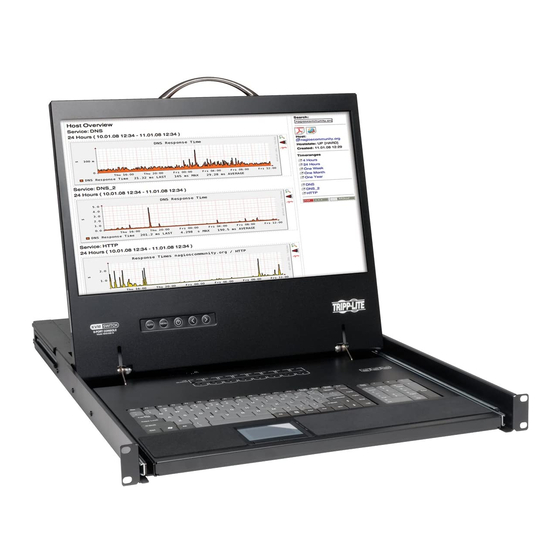
Tripp Lite B040-008-19 Quick Start Manual
Netcontroller console kvm & rackmount kvm switches
Hide thumbs
Also See for B040-008-19:
- Owner's manual (36 pages) ,
- Quick start manual (32 pages) ,
- Specifications (3 pages)
Advertisement
Quick Links
Quick Start Guide
NetController Console KVM
& Rackmount KVM Switches
Models: B040-008-19, B040-016-19, B042-004,
B042-008 & B042-016
PROTECT YOUR INVESTMENT!
Register your product for quicker service
and ultimate peace of mind.
You could also win an ISOBAR6ULTRA
surge protector—a $100 value!
www.tripplite.com/warranty
1111 W. 35th Street, Chicago, IL 60609 USA
www.tripplite.com/support
Copyright © 2017 Tripp Lite. All rights reserved.
Standard KVM Switch Rack-Mount Instructions
1 Depending on whether you want to mount the KVM switch to the
front or back of the rack, attach the included rack-mount brackets
to the front or rear side of the KVM switch.
2 Using user-supplied screws, mount the rack-mount brackets of the
KVM switch to the rack.
Standard Console KVM Switch Rack-Mount
Instructions
The B040-Series Console KVM Switches come with removable rack-
mount brackets, allowing the unit to be installed by a single person.
1 Remove the rack-mount brackets from the unit and mount them to
the back of the rack using user-supplied screws.
2 Take the Console KVM Switch and gently slide it into the rack so
that it slides into the rack-mount brackets you just mounted.
3 Mount the rack-mount brackets on the front of the unit to the rack
using user-supplied screws.
2-Post Rack Console KVM Switch Rack-Mount
Instructions
The B040-Series Console KVM Switches can be mounted to a
2-post rack using Tripp Lite's B019-000 2-Post Rack-Mount Kit
(sold separately). See the B019-000 owner's manual for installation
instructions.
Single-Stage Installation
1 Before starting the installation, shut down all computers that are to
be connected to the KVM switch.
2 Connect the external power supply (B042-Series KVMs) or power
cord (B040-Series KVMs) to the unit, and then plug it into a
Tripp Lite Surge Protector, PDU or Uninterruptible Power Supply
(UPS).
3 B042-Series KVM Switches Only: Connect a USB or PS/2
keyboard, a mouse and a monitor to the console ports on the back
of the KVM switch.
Note: Any combination of mouse and keyboard will work; PS/2 keyboard and
mouse, USB keyboard and mouse, PS/2 keyboard and USB mouse, USB
keyboard and PS/2 mouse.
4 B040-Series Console KVM Switches Only: Connect an
external USB mouse or keyboard and an external monitor to the
corresponding external console ports on the back of the unit. You
can also add remote access to the KVM switch by connecting a
B051-000 IP Remote Access unit to the external console ports on
the back of the unit. (See the B051-000 owner's manual for details
on installation.)
Note: If you are not using the External VGA Monitor port, you must connect
the External VGA Port Terminator to it for the unit to function properly.
5 Using Tripp Lite P780-Series USB/PS2 Combo KVM Cable Kits,
connect a computer to an available computer port on the back of
the unit. Repeat this step for each additional computer you are
connecting.
6 Power on the connected computers.
Daisy-Chain Installation
Terminator must
be connected
when external
VGA port is not
in use
Daisy-chain up to 16 levels
Daisy-Chain Installation
Warning! The total length of daisy-chain cable from the master
KVM switch to the last KVM switch in the installation must not
exceed 98 ft. (30 m)*. If this distance is exceeded, the KVM
installation will not function properly.
1 Connect the external power supply (B042-Series KVMs) or power
cord (B040-Series KVMs) to the Master KVM switch, and then plug
it into a Tripp Lite Surge Protector, PDU or Uninterruptible Power
Supply (UPS).
Note: B040-Series Console KVM Switches can only occupy the first position
in a daisy-chain.
2 B042-Series KVM Switches Only: Connect a USB or PS/2
keyboard, a mouse and a monitor to the console ports on the back
of the Master KVM switch.
Note: Any combination of mouse and keyboard will work; PS/2 keyboard and
mouse, USB keyboard and mouse, PS/2 keyboard and USB mouse, USB
keyboard and PS/2 mouse.
3 B040-Series Console KVM Switches Only: Connect an
external USB mouse or keyboard and an external monitor to the
corresponding external console ports on the back of the Master
Console KVM switch. You can also add remote access to the KVM
switch by connecting a B051-000 IP Remote Access unit to the
external console ports on the back of the unit. (See the B051-000
owner's manual for details on installation.)
Note: If you are not using the External VGA Monitor port, you must connect
the External VGA Port Terminator to it for the unit to function properly.
4 Using the included 8" Daisy-Chain Cable, or a P781-Series Daisy-
Chain Cable (sold separately), connect the Daisy-Chain Out port of
the Master KVM switch to the Daisy-Chain In port of the second-
level B042-Series KVM Switch.
Note: The maximum distance between any two daisy-chained KVM switches
is 98 ft (30 m)*.
P780 series
5 Connect the external power supply to the second-level B042-Series
cable kit
KVM Switch and then plug it into a Tripp Lite Surge Protector, PDU
or Uninterruptible Power Supply (UPS). Repeat Steps 4 and 5 for
any additional KVM switches you are adding, with no more than 16
KVM switches in the entire installation.
Note: The total length of daisy-chain cable from the master KVM switch to
the last KVM switch in the installation must not exceed 98 ft. (30 m)*. If this
distance is exceeded, the KVM installation will not function properly.
6 After you have daisy-chained all of the KVM switches, connect
the Daisy-Chain Terminator that came with your B042-Series
KVM Switch to the Daisy-Chain Out port of the last KVM in the
installation.
7 Using Tripp Lite P780-Series USB/PS2 Combo KVM Cable
Kits, connect a computer to an available computer port on the
installation. Repeat this step for each additional computer you are
connecting.
P780 series
cables
8 Power on the connected computers.
* Previous versions of NetController KVM Switches may not support these
distances. If you experience problems when daisy-chaining within the max.
BANK 16
distance requirements, you may need to upgrade the firmware of your unit.
(See the manual CD for details on performing a firmware upgrade.)
continued
Advertisement

Related Manuals for Tripp Lite B040-008-19


Summary of Contents for Tripp Lite B040-008-19
- Page 1 KVM switch. KVM Switch and then plug it into a Tripp Lite Surge Protector, PDU or Uninterruptible Power Supply (UPS). Repeat Steps 4 and 5 for 2 Using user-supplied screws, mount the rack-mount brackets of the any additional KVM switches you are adding, with no more than 16 KVM switch to the rack.
- Page 2 Product Registration prepaid) to: Tripp Lite; 1111 W. 35th Street; Chicago IL 60609; USA. Seller will pay return shipping charges. Visit www.tripplite.com/warranty today to register your new Tripp Lite product. You’ll be Visit www.tripplite.com/support before sending any equipment back for repair.