Makita DHR165 Technical Information
Hide thumbs
Also See for DHR165:
- Instruction manual (65 pages) ,
- Instruction manual (73 pages) ,
- Instruction manual (48 pages)
Table of Contents
Advertisement
Quick Links
T
ECHNICAL INFORMATION
Model No.
Description
C
ONCEPT AND MAIN APPLICATIONS
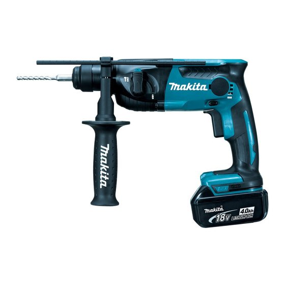
Models DHR165/DHR164 are 18V/14.4V LXT cordless rotary hammers
and have been developed based on the current 14.4V LXT model DHR162.
The two models feature XPT (eXtreme Protection Technology)
in addition to the benefits of the compact and lightweight DHR162.
18V model DHR165 has been developed to expand our lineup of
18V LXT cordless rotary hammers, while 14.4V model DHR164
has been developed as an upgraded model of DHR162.
Note: DHR165 is not compatible with BL1815.
DHR164 is not compatible with BL1415.
S
pecification
Specification
Voltage: V
Capacity: Ah
Energy capacity: Wh
Battery
Cell
Charging time (approx): min
Max output: W
No load speed: min
¹= rpm
ˉ
Impacts per minute: min
Shank type
Shank diameter: mm (")
Chuck type
Concrete
Capacity: mm (")
Steel
Wood
Operation mode
Electric brake
Variable speed control by trigger
Reverse switch
Torque limiter
LED job light
Weight according to
EPTA-Procedure 01/2003*
*3 With Side grip
*4 With BL1815N or BL1820
*5 With BL1830, BL1840 or BL1850
*6 With BL1415N
*7 With BL1430, BL1430A, BL1440 or BL1450
DHR165/ DHR164
16mm (5/8") Cordless Rotary Hammer
Model
¹
ˉ
: kg (lbs)
3
Length (L)
Width (W)
Height (H)
*1 DHR165: With BL1815N or BL1820
*2 DHR165: With BL1830, BL1840 or BL1850
DHR165
18
1.5, 2.0, 3.0, 4.0, 5.0
27, 36, 54, 72, 90
Li-ion
15, 24, 22, 36, 45
with DC18RC
400
0 - 1,600
0 - 5,300
Adapted for SDS-PLUS bits
One-touch sliding chuck
24 (15/16)
2 modes (Rotation only/ Rotation with hammering)
2.2 (4.9)*
4
2.5 (5.5)*
5
for ASC & Sales Shop
W
L
DHR165
Dimensions: mm (")
297 (11-3/4)
79 (3-1/8)
236 (9-1/4)*
1
253 (10)*
2
DHR164: With BL1415N or BL1415NA
DHR164: With BL1430, BL1430A, BL1440
or BL1450
DHR164
14.4
1.5, 3.0, 4.0, 5.0
22, 44, 58, 5.0
Li-ion
15, 22, 36, 45
with DC18RC
400
0 - 1,600
0 - 5,300
10 (3/8)
16 (5/8)
13 (1/2)
Yes
Yes
Yes
Yes
Yes
2.2 (4.8)*
2.4 (5.3)*
OFFICIAL USE
PRODUCT
P 1/ 17
H
DHR164
235 (9-1/4)*
1
250 (9-7/8)*
2
6
7
Advertisement
Table of Contents

Related Manuals for Makita DHR165


Summary of Contents for Makita DHR165
- Page 1 The two models feature XPT (eXtreme Protection Technology) in addition to the benefits of the compact and lightweight DHR162. 18V model DHR165 has been developed to expand our lineup of 18V LXT cordless rotary hammers, while 14.4V model DHR164 DHR165 DHR164 has been developed as an upgraded model of DHR162.
-
Page 2: Standard Equipment
*10 For some countries Note: The standard equipment may vary by country or model variation. ptional accessories SDS-PLUS shank TCT hammer drill bits Battery BL1815N (for DHR165) Taper shank TCT hammer drill bits Battery BL1820 (for DHR165) Taper shank adapter... -
Page 3: Maintenance Program
Removing Pin 4 from Inner housing 1R306 Ring spring removing jig Removing Retaining ring WR-25 *331708-8 Piston cylinder Assembling Ring spring 22 into Tool holder *Use Piston cylinder of DHR162, DHR164, DHR165 and HR1830 (Part No. 331708-8) as a repairing tool. - Page 4 Oil seal 25 because it should be pressfit in place without twisting/ deforming. 3g: Gear teeth and Flat washer 5g: Inner housing and on gear teeth side 20g: Makita grease RA No.1 the components (except grease FA No. 2 and Molybdenum disulfide)
- Page 5 P 5/ 17 epair [3] DISASSEMBLY/ASSEMBLY [3]-1. Tool holder DISASSEMBLING Tool holder section can be disassembled as drawn in Fig. 2. Fig. 2 Remove Cap 35 with slotted screwdriver, then Separate Chuck cover. Bit holder section can be remove Ring spring 19 using 1R003 with 1R212. Then remove Steel ball 7.0 while disassembled as drawn below.
- Page 6 P 6/ 17 epair [3] DISASSEMBLY/ASSEMBLY [3]-2. Armature (cont.) DISASSEMBLING (2) In case Armature cannot be removed by the steps mentioned in the previous page, disassemble the machine as drawn in the following and the next page. (3) Remove Change lever complete, and separate Inner housing section from Gear housing. Then separate Tool holder section and Joint plate from the Inner housing section as drawn in Fig.
- Page 7 P 7/ 17 epair [3] DISASSEMBLY/ASSEMBLY [3]-2. Armature (cont.) DISASSEMBLING (4) Disassemble Spur gear 10 and Swash bearing section as drawn in Fig. 7. (5) Armature can be removed from Inner housing complete as drawn in Fig. 8. Fig. 7 Note: Separating Spur gear 10 with Swash bearing section 1.
- Page 8 P 8/ 17 epair [3] DISASSEMBLY/ASSEMBLY [3]-2. Armature (cont.) ASSEMBLING (1) Armature can be assembled to Inner housing complete as drawn in Fig. 9. Fig. 9 1. Assemble Armature to Inner housing complete 2. Tap Armature shaft carefully with a plastic hammer by hand until Ball bearing on Armature fan side to set Ball bearing of Armature in place in Inner reaches O ring 24.
- Page 9 P 9/ 17 epair [3] DISASSEMBLY/ASSEMBLY [3]-3. Gear section DISASSEMBLING (1) Disassemble Tool holder section, Joint plate from Piston cylinder. (Fig. 6 in page 6) (2) Remove Spur gear 10 and Swash bearing section from Piston cylinder and Inner housing complete. (Fig. 7 in page 7) (3) Spur gear 46 can be removed as the upper drawing in Fig.
- Page 10 P 10/ 17 epair [3] DISASSEMBLY/ASSEMBLY [3]-3. Gear section (cont.) DISASSEMBLING (3) Ball bearings 606ZZ on the both ends of Spur gear 10 are still left when Spur gear 10 and Swash bearing section are removed from Gear housing complete and Inner housing complete. These Ball bearings can be removed as drawn in Fig.
- Page 11 P 11/ 17 epair Fig. 12 [3] DISASSEMBLY/ASSEMBLY [3]-3. Gear section (cont.) DISASSEMBLING (4) As for Oil seal 25 and Ball bearing 6805LLB, remove them from Gear housing complete by four notches tapping the four notches on the top of Gear housing complete in a crisscross manner using a slotted screwdriver and plastic hammer.
- Page 12 P 12/ 17 epair [3] DISASSEMBLY/ASSEMBLY [3]-3. Gear section (cont.) ASSEMBLING (3) Assemble Tool holder section. Refer to the upper drawings in Fig. 10. (4) Assemble the rest parts by reversing the disassembly procedure. Be careful about the matter as drawn in Fig. 15. Fig.
- Page 13 P 13/ 17 epair [3] DISASSEMBLY/ASSEMBLY [3]-4. Inner housing complete (cont.) ASSEMBLING Assemble Inner housing complete as drawn in Fig. 17. Fig. 17 1. Put a new Felt 4x3 into the hole of 2. While aligning the holes of 3. While aligning passing holes Inner housing complete, and then Change plate and Inner housing of Stopper plate to the sames...
- Page 14 P 14/ 17 epair [3] DISASSEMBLY/ASSEMBLY [3]-5. Impact bolt DISASSEMBLING (1) Disassemble the parts on the top of Tool holder section. (Fig. 2 of page 5) Remove Carbon brushes. (Fig. 4 of page 5) (2) Remove Inner housing section from Gear housing complete, and separate Tool holder complete from Piston cylinder (Fig.
- Page 15 P 15/ 17 epair [3] DISASSEMBLY/ASSEMBLY [3]-5. Impact bolt (cont.) ASSEMBLING Assemble Impact bolt as drawn in Fig. 20. Fig. 20 1. Mount X ring 13 2. Mount X ring 13 and Ring 11 3. Put X ring 13, Ring 11 and Impact bolt to Ring 11.
-
Page 16: Circuit Diagram
P 16/ 17 ircuit diagram Fig. D-1 Color index of lead wires' sheath Black Blue White Orange Yellow Endbell complete Line filter** Lead wire (16AWG*) Insulated connector (M3.5) Endbell Lead wire Lead wire (16AWG*) (24AWG*) Lead wire (20AWG*) Red Lead wire is used for some countries instead of white. -
Page 17: Wiring Diagram
P 17/ 17 iring diagram Fig. D-2 Wiring in Housing set L If Line filters are used, fix Lead wires If Line filters are used, put them respectively into the places (black, red) of Endbell complete on left side and right side of Lead wire holder (A) as follows: in Lead wire holders (A) and (B).