Advertisement
Quick Links
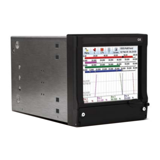
QX Recorders - Installation Instruction
Portable Case
This Installation Instruction sheet is intended as a guide for replacing or installing hardware and for setting up
functionality in the recorder. Refer to the User manual for detailed operational requirements.
The QX recorders are designed for ease of assembly with minimal disturbance to the rest of the unit. If unsure, please
return the unit to your supplier for repair or upgrade.
Removing the case and opening the back of the recorder should only be performed under the following circumstances:
When an item of hardware requires individual replacement.
When an item of hardware is to be retrospectively fitted.
In all other instances it is recommended that the complete unit be returned to an authorised agent or service centre.
For Agency Approved recorders the product needs to be upgraded or repaired by an Authorized Repair facility
WARNING
HAZARDOUS VOLTAGES
Disconnect all power to the recorder before removing the case and attempting any maintenance procedures.
SAFETY TESTS
Upon completion of service procedures detailed in this manual two basic safety tests should be performed in order to
ensure continued safe operation of the instrument.
Earth Resistance; 25 VDC applied between case and protective earth, bonding resistance should be < 0.1 Ohm.
Insulation Resistance; 500Vdc applied between the earth terminal, and the live and neutral terminal shorted together,
insulation resistance to be >2.0 MOhm. (Mega Ohm, NOT milli Ohm)
Failure to comply with these instructions could result in death or serious injury
CAUTION
OBSERVE ANTI-STATIC PRECAUTIONS
Refer to BS EN61340-5-1: 2001. Basic specification. Protection of electrostatic sensitive devices.
Full anti-static precautions MUST be observed when in contact with the electronics of your recorder.
SAVE DATA, SETUPS AND LAYOUTS
Removal of PCBs and battery back-up will result in the loss of all non-volatile data.
Ensure all data and set-ups are saved.
Failure to comply with these instructions may result in product damage.
43-TV-33-62 iss.1 GLO Oct 06 UK
QX Recorder
1
Advertisement

Related Manuals for Honeywell QX Series


Summary of Contents for Honeywell QX Series
- Page 1 QX Recorders - Installation Instruction Portable Case QX Recorder This Installation Instruction sheet is intended as a guide for replacing or installing hardware and for setting up functionality in the recorder. Refer to the User manual for detailed operational requirements. The QX recorders are designed for ease of assembly with minimal disturbance to the rest of the unit.
- Page 2 Before attempting to repair or upgrade a recorder, it is advisable to clear a sufficient work space so components such as the front panel can be rested on the work surface without getting scratched or damaged. Fitting the Portable case Unpack the portable case kit and check all the parts are present.
- Page 3 Slide the metal handle inner into the black plastic cover. Place the case down as shown in Fig 1 with the ventilation slots uppermost. The handle fixes to the 2 holes along the centre of the case. Place one of the handle fixings on one end of the handle. Place it on the case and align the holes. See fig 2 Fig 2 Place one of the handle fixing screws through the fixing, through the handle and through the case.
- Page 4 Fit the handle fixings covers. These cover the screws. Fit as shown in figs 4 and 5 below. Fig 5 Fig 4 Clip cover under Push cover down front edge to clip in place Turn the case upside down and attach the 4 self adhesive feet in the positions shown in Fig 6 below. Fig 6 To remove the existing case from the recorder, remove the 4 M3 screws, 2 in each side.
- Page 5 Fig 7 Remove the 2 screws on each side of the case The case can then be removed from the recorder, complete with back panel by sliding backwards. To fit the new portable case, carefully slide it on from the rear of the recorder. Ensure the case is orientated with the handle on the top of the recorder.
- Page 6 To replace the rear panel on the new case, angle the rear panel as shown to line up two location points with the floor of the recorder’s case. Fig 9 Re-fit the M3 screw in the top right hand corner. See Fig 10 Fig 10 43-TV-33-62 iss.1 GLO Oct 06 UK...
-
Page 7: Terminal Cover
Terminal Cover When in use the terminal cover should be fitted to protect the user from any hazardous voltages that may be present on the connectors plugged into the back of the recorder. Clearly the cover should not be fitted until all connections have been made to the back of the recorder.