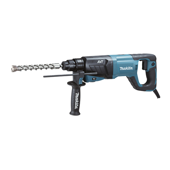
Makita HR2641 Technical Information
26mm (1") combination hammer
Hide thumbs
Also See for HR2641:
- Instruction manual (88 pages) ,
- Instruction manual (41 pages) ,
- Instruction manual (77 pages)
Advertisement
Quick Links
T
ECHNICAL INFORMATION
Model No.
Description
C
ONCEPT AND MAIN APPLICATIONS
Model HR2641 is a 26mm (1") D-handle combination hammer
developed based on model HR2621 to enhance Operation mode
change lever.
Its main features are:
• Other features except the modification of Operation mode change lever
remain the same as model HR2621.
• 3 modes (Rotation only/ Rotation with hammering/ Hammering only)
• AVT (Anti-Vibration Technology) is equipped to obtain extremely low vibration.
S
pecification
Voltage (V)
110
120
220
230
240
Specification
No load speed: min.
ˉ
Impacts per minute: min
Shank type
Chuck type
Concrete
Capacities:
mm (")
Steel
Wood
Impact energy according to EPTA 05/2009: J
(ft.lbs)
Operation mode
Variable speed control
Rotation reversing facility
Torque limiter
LED Job light
Protection from electric shock
Power supply cord: m (ft)
Weight according to
EPTA-Procedure 01/2003*: kg (lbs)
HR2641
26mm (1") Combination Hammer
Current (A)
Cycle (Hz)
7.7
50/60
8.0
50/60
3.8
50/60
3.7
50/60
3.5
50/60
Model No.
¹= rpm
¹= ipm
ˉ
TCT bit
Core bit
Diamond core bit
Continuous Rating (W)
Input
800
N/A
800
800
800
Adapted for SDS-PLUS shank bits
One-touch sliding chuck
68 (2-11/16)
80 (3-1/8)
32 (1-1/4)
(Rotation only/ Rotation with hammering/ Hammering only)
Yes (by trigger)
Double insulation
Europe, North America: 4.0 (13.1), Australia, Brazil: 2.0 (6.6),
Other countries: 2.5 (8.2)
OFFICIAL USE
for ASC & Sales Shop
PRODUCT
L
W
Dimensions: mm ( " )
Length (L)
422 (16-5/8)
Width (W)
Height (H)
156 (6-1/8)
Max Output (W)
Output
370
370
370
370
370
HR2641
0 - 1,100
0 - 4,500
26 (1)
13 (1/2)
2.4
3 modes
Yes
Yes
No
3.1 (6.8)
P 1/ 25
H
76 (3)
650
650
650
650
650
Advertisement

Related Manuals for Makita HR2641


Summary of Contents for Makita HR2641
- Page 1 Model No. HR2641 Description 26mm (1") Combination Hammer ONCEPT AND MAIN APPLICATIONS Model HR2641 is a 26mm (1") D-handle combination hammer developed based on model HR2621 to enhance Operation mode change lever. Dimensions: mm ( " ) Its main features are:...
- Page 2 P 2/ 25 tandard equipment Depth gauge Dust cup (for some countries only) Quick change drill chuck (keyless) Side grip Carrying case (plastic or aluminum) Note: The standard equipment may vary by country or model variation. ptional accessories SDS-PLUS shank TCT hammer drill bits Waterproof cover Taper shank TCT hammer drill bits Quick change drill chuck (keyless)
- Page 3 P 3/ 25 epair CAUTION: Repair the machine in accordance with “Instruction manual” or “Safety instructions”. [1] NECESSARY REPAIRING TOOLS Code No. Description Use for 1R003 Retaining ring S pliers ST-2N removing Ring spring 14 1R212 Tip for Retaining ring pliers assembling Helical gear 26 1R032 Bearing setting plate 8.2...
- Page 4 Weight holder guide Portion that Inner housing complete touches a little Pin 6 Portions to be inserted to 80 and 82 Inside that 80 touches Counter weight Fig. 1 Makita grease RB No.00 Molybdenum desulfide lubricant Inner housing complete Ring 8...
-
Page 5: Table Of Contents
Note: • Washer 16, Ring 21, Guide washer and Conical compression spring 21-29 are not reversible, and therefore, be careful about the direction. See Fig. 3. • Apply Makita grease No. RB No. 00 to two Steel balls 7.0 to prevent them from falling off. Refer to Fig. 1 of page 4. - Page 6 P 6/ 25 epair [3] DISASSEMBLY/ASSEMBLY [3]-2. Change lever DISASSEMBLING Disassemble Change lever section as drawn in Fig. 4. Fig. 4 1. Insert a slotted screwdriver to the notches of Gear housing 2. Change lever cap, Change lever with Rubber pin 4 and lever it up alternately.
- Page 7 P 7/ 25 epair [3] DISASSEMBLY/ASSEMBLY [3]-3. Armature DISASSEMBLING Remove Armature as drawn in Fig. 6. Fig. 6 1. After removing Handle cover, 2. Remove four 4x30 Tapping screws and then pull off Gear housing complete. disconnect entirely Brush hoder Armature can be removed together with Gear housing complete.
- Page 8 P 8/ 25 epair [3] DISASSEMBLY/ASSEMBLY [3]-3. Armature (cont.) ASSEMBLING Assemble by reversing the disassembly procedures. Refer to the notes shown in Figs. 7 and 8. Fig. 7 Fig. 8 Note: Be sure to put Wave washer 15 into bearing room Note: Do not fail to assemble Flat washer 10 before in Motor housing.
- Page 9 P 9/ 25 epair [3] DISASSEMBLY/ASSEMBLY [3]-4. Torque limiter section DISASSEMBLING (1) Disassemble Bit holder section as drawn in Fig. 2 of page 5. (2) Disassemble Change lever section as drawn in Fig. 4 of page 6. (3) Disconnecting Carbon brush from Commutator of Armature, pull off Armature from Gear housing complete as drawn in Fig.
- Page 10 31 as drawn in Fig. 10, the other is placed on Inner housing complete as drawn in Fig. 9 of page 9. Be sure to apply Makita grease RB No. 00 according to the instruction in Fig. 1 of page 4.
-
Page 11: Fig. 12
P 11/ 25 epair [3] DISASSEMBLY/ASSEMBLY [3]-5. Impact bolt DISASSEMBLING (1) Disassemble Bit holder section as drawn in Fig. 2 of page 5. (2) Disassemble Tool holder section. Refer to Fig. 9 of page 9. Ring spring 28 prevents O-ring case B from sliding toward Inner housing complete side, and their allowance is too tight to apply tools for removing Ring spring 28 as drawn in Fig. -
Page 12: Assembling
P 12/ 25 epair [3] DISASSEMBLY/ASSEMBLY [3]-5. Impact bolt (cont) DISASSEMBLING (3) Disassemble Impact bolt section as drawn in Fig. 14. Fig. 14 1. Insert a rod or screwdriver into Tool holder 2. The following parts are pushed out from Tool holder complete. 2. - Page 13 P 13/25 epair [3] DISASSEMBLY/ASSEMBLY [3]-6. Swash bearing 10, Inner housing section DISASSEMBLING (1) Disassemble Bit holder section as drawn in Fig. 2 of page 5. (2) Disassemble Change lever section as drawn in Fig. 4 of page 6. (3) Disconnect Carbon brushes from Commutator of Armature, and then pull out Armature from Gear housing complete as drawn in Fig.
- Page 14 P 14/ 25 epair [3] DISASSEMBLY/ASSEMBLY [3]-6. Swash bearing 10, Inner housing section (cont.) DISASSEMBLING (6) Disassemble Cam shaft portion as drawn in Fig. 17. Then check O Ring 17.5 as drawn in Fig. 18. Fig. 18 Fig. 17 Try inserting Striker into Piston cylinder and pulling it out. Already removed in the step shown in When you have something resistant through the process and you can Fig.
- Page 15 Guide plate Compression spring 14 ASSEMBLING Note: The Swash bearing for HR2641 (with AVT) is different from that for HR2630T (without AVT) as drawn in Fig. 22. Be careful not to mix them up. Fig. 22 Swash bearings for HR2641 with AVT...
- Page 16 P 16/ 25 epair [3] DISASSEMBLY/ASSEMBLY [3]-6. Swash bearing 10, Inner housing section ASSEMBLING (1) Assemble Swash bearing section as drawn in Fig. 23. Fig. 23 2. Stand Cam shaft on 1R032, and then pass the Cam shaft through Swash bearing 10, 1.
- Page 17 P 17/ 25 epair [3] DISASSEMBLY/ASSEMBLY [3]-6. Swash bearing 10, Inner housing section ASSEMBLING (3) Refer to Fig. 25. Note: Apply grease according to Fig. 1 of page 4. Fig. 25 1. Tighten Swash bearing section with 2. Mount Striker into Piston cylinder. 3.
- Page 18 P 18/ 25 epair [3] DISASSEMBLY/ASSEMBLY [3]-6. Swash bearing 10, Inner housing section (cont.) ASSEMBLING (4) Assemble Change plate B to Change plate A as drawn in Fig. 26. Fig. 26 1. Assemble one end of 2. Pass the tabs of Change plate A through the holes of Change plate B, and assemble Compression spring 5 to Change plate A to Change plate B by inserting the another end of Compression the rib of Change plate A.
- Page 19 P 19/ 25 epair [3] DISASSEMBLY/ASSEMBLY [3]-6. Swash bearing 10, Inner housing section (cont.) ASSEMBLING (7) Assemble Gear housing complete to Inner housing complete carefully in vertical direction as drawn in Fig. 31. Fig. 31 Lock plate is easily fallen off from Gear housing Hold Lock plate by finger complete as drawn below, and therefore, support through the hole of Change lever.
- Page 20 P 20/ 25 epair [3] DISASSEMBLY/ASSEMBLY [3]-7. The components for Gear housing complete DISASSEMBLING Oil seal 25, Cup sleeve, Ball bearing 6806LLB are factory assembled in Gear housing complete. These parts can be replaced from Gear housing complete individually with new ones. (1) Disassemble Bit holder section as drawn in Fig.
- Page 21 P 21/ 25 epair [3] DISASSEMBLY/ASSEMBLY [3]-7. The components for Gear housing complete (cont.) ASSEMBLING Oil seal 25, Cup sleeve, Ball bearing 6806LLB can be assembled to Inner housing complete as drawn in Fig. 33. Fig. 33 1. Receive the stepped collar of Gear housing complete 2.
- Page 22 P 22/ 25 epair [4] MAINTENANCE PROGRAM It is recommended to replace the following parts at the same time when the worn Carbon brushes are replaced with new ones. (Fig. 34) Fig. 34 Item No. Q’ty Part No. Description Tool holder complete 286288-8 Cap 35 233989-9...
- Page 23 P 23/ 25 ircuit diagram Fig. D-1 Color index of lead wires' sheath Clear Brown White Black Orange Purple Blue Circuit with equipment Circuit without equipment for Radio interference suppression for Radio interference suppression Brush Brush Brush Brush holder holder holder holder Field...
- Page 24 P 24/ 25 iring diagram Fig. D-2 Wiring of Grounding lead wire (clear) for Radio interference suppression Commutator side Clamp Noise suppressor Connecting lead wire in Handle section Grounding terminal of Noise suppressor Mount Grounding terminal to Field core at the place between Terminal plate and Clamp.
- Page 25 P 25/ 25 iring diagram Fig. D-4 Wiring in Handle section Connect Flag receptacles to Brush holders so that their wire connected portions and the lead wires come to the bottom of Handle side. Their wire connected portions and the lead wires must not face Handle cover side.