Makita DTD152 Technical Information
Hide thumbs
Also See for DTD152:
- Instruction manual (65 pages) ,
- Instruction manual (65 pages) ,
- Instruction manual (53 pages)
Table of Contents
Advertisement
T
ECHNICAL INFORMATION
Model No.
Description
C
ONCEPT AND MAIN APPLICATIONS
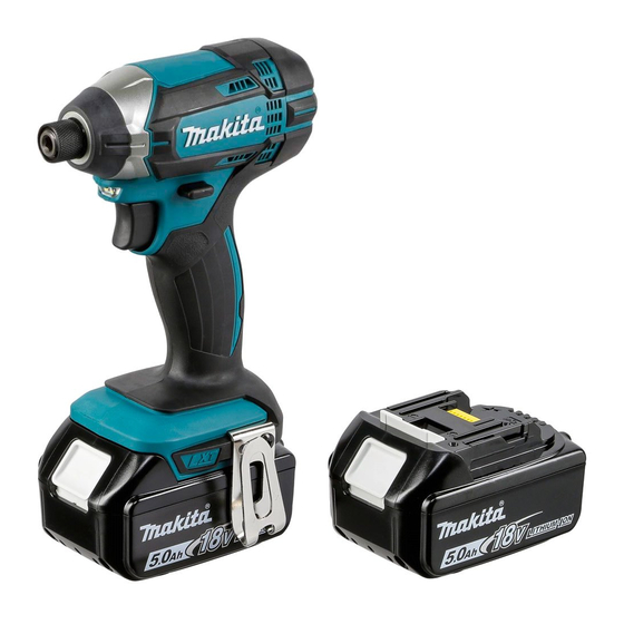
Model DTD152 is a cordless impact driver powered by 18V Li-ion battery
and developed for main applications such as tightening of self-drilling screws or
light duty machine screws.
The main features and benefits are:
• High rotational speed: 2,900 rpm -ı
• Compact and lightweight design
This product is compatible with the following 18V Li-ion batteries:
BL1815 (1.3Ah)/ BL1815N (1.5Ah)/ BL1820 (2.0Ah)/
BL1830 (3.0Ah)/ BL1840 (4.0Ah)/ BL1850 (5.0Ah)
S
pecification
Specification
Voltage: V
Capacity: Ah
Battery
Energy capacity: Wh
Cell
Charging time (approx): min
Max output (W)
Driving shank
Machine screw
Standard bolt
Capacities
High strength bolt
Coarse-thread
Impacts per minute: min -ı = ipm
No load speed: min -ı = rpm
Max. tightening torque
Electric brake
Variable speed control by trigger
Reverse switch
LED job light
Weight according to
EPTA-Procedure 01/2003: kg (lbs)
*3 Tightening torque at 3 seconds after seating, when tightening M14 (grade 10.9) high strength bolt.
S
tandard equipment
Belt clip
Battery*
, Battery cover*
4
Charger*
, Plastic carrying case*
4
O
ptional accessories
Socket bits
Drill chucks
Drill bits with 6.35mm Hex shank
Hole saws for impact driver
Bit piece
Stopper for impact driver
Hook set (Belt clip)
Battery protectors
DTD152
Cordless Impact Driver
Model
: N·m [kgf·cm] (in·lbs)
*3
*4 Battery, charger and plastic carrying case are not supplied with "Z" model.
*5 Supplied with the same quantity of extra Battery.
5
,
Note: The standard equipment may vary by country or model variation.
4
Li-ion Battery BL1815
Li-ion Battery BL1815N
Li-ion Battery BL1820
Li-ion Battery BL1830
Li-ion Battery BL1840
Li-ion Battery BL1850
Length (L)
Width (W)
Height (H)
*1 With Battery BL1815/ BL1815N/ BL1820
*2 With Battery BL1830/ BL1840/ BL1850
DTD152
18
1.3, 1.5, 2.0, 3.0, 4.0, 5.0
24, 27, 36, 54, 72, 90
Li-ion
15, 15, 24, 22, 36, 45 with DC18RC
240
6.35mm (1/4") Hex
M4 - M8 (5/32 - 5/16")
M5 - M16 (3/16 - 5/8")
M5 - M12 (3/16 - 1/2")
22 - 125mm (7/8 - 4-7/8")
0 - 3,500
0 - 2,900
165 [1,680] (1,460)
Yes
Yes
Yes
Yes
1.3 (2.8)*
or
1
1.5 (3.3)*
2
Charger DC18SD
Charger DC24SC
Fast charger DC18RC
Automotive charger DC18SE
Four Port Charger DC18SF
Two Port Fast charger DC18RD
OFFICIAL USE
for ASC & Sales Shop
PRODUCT
P 1/ 27
July 2015
L
H
W
Dimensions: mm (")
137 (5-3/8)
79 (3-1/8)
220 (8-5/8)*
1
238 (9-3/8)*
2
Advertisement
Table of Contents

Related Manuals for Makita DTD152


Summary of Contents for Makita DTD152
- Page 1 Cordless Impact Driver Description ONCEPT AND MAIN APPLICATIONS Model DTD152 is a cordless impact driver powered by 18V Li-ion battery and developed for main applications such as tightening of self-drilling screws or light duty machine screws. The main features and benefits are: •...
-
Page 2: Table Of Contents
July 2015 CONTENTS Exploded diagram .................................. 4 About This Manual ................................. 5 Repair ..................................... 5 3.1. NECESSARY REPAIRING TOOLS ............................5 3.2. LUBRICANT AND ADHESIVE APPLICATION ........................6 3.3. DISASSEMBLY/ASSEMBLY .............................. 7 3.3.1. Hammer case complete ............................7 3.3.1.1. Disassembling ..............................7 3.3.1.2. - Page 3 July 2015 Assembly of Brush holder complete to Armature ....................... 25 6.1. Overview ..................................25 6.2. Caution ..................................25 6.3. Assembling procedure ..............................26 Assembly of Carbon brush ..............................27 3 / 27...
-
Page 4: Exploded Diagram
July 2015 EXPLODED DIAGRAM Figure 1 4 / 27... -
Page 5: About This Manual
July 2015 ABOUT THIS MANUAL The number in the parenthesis () is the item number on the exploded diagram (Figure REPAIR Repair the machine in accordance with “Instruction manual” or “Safety instructions”. 3.1. NECESSARY REPAIRING TOOLS Code No. Description Use for 1R003 Retaining ring pliers ST-2N removing Ring spring 11 (8) -
Page 6: Lubricant And Adhesive Application
Description Portion to lubricate Lubricant Amount Hammer case complete Inside of Sleeve 14 which touches Anvil (16) Makita grease FA. No.2 a little Anvil Hole into which Spindle (23) top is inserted Steel ball 3.5 (24pcs.) Whole portion Steel ball 5.6 (2pcs.) Whole portion Seal lubricant No.101... -
Page 7: Disassembly/Assembly
July 2015 3.3. DISASSEMBLY/ASSEMBLY 3.3.1. HAMMER CASE COMPLETE 3.3.1.1. DISASSEMBLING 1. Remove Bumper (12) with a small slotted screwdriver. (12) Slotted screwdriver Figure 3 2. Loosen ten 3x16 tapping screws (35) and remove Rear cover (34) and Housing R (36). (34) (36) (35) - Page 8 July 2015 4. Remove Hammer case section (8-28) from Motor section (29-33) (8-28) (29-33). Figure 6 5. Fix Socket 32-50 with two 1R040 and Vise. (8-28) 6. Set Hammer case section (8-28) to Socket 32-50. Socket 32-50 Vise 1R040 Figure 7 7.
-
Page 9: Assembling
July 2015 3.3.1.2. ASSEMBLING 1. Put O ring 40 (27) into the groove of Bearing box (26) complete (28). 2. Put the small diameter portion of Internal gear 51 (26) on O ring 40 (27) in Bearing box complete (28). (27) Groove of Bearing box complete (28) - Page 10 July 2015 5. Fix Socket 32-50 with two 1R040 and Vise. 6. Set Hammer case section (8-28) to Socket 32-50. (8-28) Vise Socket 32-50 1R040 Figure 12 7. Turn 1R223 counterclockwise. 1R224 1R223 Note: The fastening torque must be 45 to 55 N·m. (460 ~ 560 kgf·cm) Socket 30-78 Figure 13...
-
Page 11: Armature
July 2015 3.3.2. ARMATURE 3.3.2.1. DISASSEMBLING (29-33) (8-28) 1. Remove Hammer case section (8-28) from Motor section Figure (29-33). (See Figure 15 2. Shift the tail of Torsion spring from the top of Carbon (31) Tail of Torsion brush (31) to the Notch of Brush holder complete (32). spring Carbon brush (31) gets free from the pressure of Torsion (32) -
Page 12: Assembling
July 2015 5. Press the drive end of Armature (30) to a workbench to separate Armature (30) from Yoke unit (29). (30) (29) Drive end of Armature (30) Figure 19 3.3.2.2. ASSEMBLING 1. Face the notch of Yoke unit (29) to the drive-end side Drive end of Armature (30) of Armature (30). - Page 13 July 2015 4. Insert the drive end of Armature (30) into Bearing box complete (28) while engaging the drive end of Armature (30) with Spur gears in Hammer case section (8-28) to rotate them smoothly. Drive end of Armature (30) (28) (8-28) Figure 22...
- Page 14 July 2015 Projection of Hammer case 6. Mount Hammer case section (8-28) and Motor section Notch of Yoke unit (29) complete (13) (29-33) to Housing L (36) while checking the following points: - align the notch of Yoke unit (29) with the projection of Housing L (36) - align the projection of Hammer case complete (13) with the groove of Housing L (36)
-
Page 15: Anvil
July 2015 8. Insert Carbon brush (31) into Brush holder complete (32). (31) Tail of Torsion spring Shift the tail of Torsion spring from the Notch of Brush (32) holder complete (32) to the top of Carbon brush (31). Carbon brush (31) is locked with the pressure of Torsion spring. -
Page 16: Assembling
July 2015 3. Use 1R232 for holding Anvil (16) inside of Hammer case complete (13) firmly for easy removal of Ring spring 11 (8). (13) 1R232 Figure 29 4. Remove Ring spring 11 (8) while checking the following 1R212-A 1R212-B points. -
Page 17: Hammer Section
July 2015 3.3.4. HAMMER SECTION 3.3.4.1. DISASSEMBLING 1. Remove Hammer case section (8-28) from Motor section (28) (27) Figure (29-33). (See 2. Remove Bearing box complete (28), O ring 40 (27), Internal gear 51 (26), Hammer section (17-25), Hammer Figure 7 Figure case complete section (8-16). -
Page 18: Assembling
July 2015 (17) 9. Hammer section (17-25) can be disassembled as shown in the figure on the left: (18) - Hammer (17) (19) - Steel ball 3.5 (18) (x24) (20) - Flat washer 24 (19) - Compression spring 25 (20) (23) - Spindle (23) Figure 35... -
Page 19: Circuit Diagram
July 2015 CIRCUIT DIAGRAM Color index of lead wires' sheath Black Blue White Yellow Brush holder complete Line filter (2 holes type) (Line filter is not used for some countries) AWG16 AWG22 (Not used for some Earth terminal countries) AWG16 Non-insulated terminal Insulated connector (Not used for some... -
Page 20: Repair Of Led Circuit
July 2015 4.1. REPAIR OF LED CIRCUIT - Use Non-insulated connector and Polyolefin tube (inner diameter: ø4.0mm) as shown below. Figure 48. (Cut lead wires if necessary.) - When repairing, put terminals in the designated position shown in Color index of lead wires' sheath Black White End face of... -
Page 21: Wiring Diagram
July 2015 WIRING DIAGRAM 5.1. LED SECTION Area A LED Lead wires must be tight in Area A. Put these Lead wires into any of these Lead wire holders. Area B LED Lead wires must not be crossed in Area B. Figure 41 5.2. -
Page 22: Switch
July 2015 5.3. SWITCH 1. Connect M1 terminal of Lead wire (red) to Switch (6) M1 terminal of Lead wire (red) vertically. M1 Terminal Figure 43 2. Connect M2 terminal of Lead wire (black) to Switch (6) 25 to 30° with it tilted at 25 to 30°... - Page 23 July 2015 5. Put Lead wire of earth terminal (if used) into Lead wire Lead wire of earth terminal holders. Lead wire holders Figure 47 23 / 27...
-
Page 24: Housing Section
July 2015 5.4. HOUSING SECTION Lead wire holder (32) Do not put Lead wire of earth terminal (if used) onto Area C (between Rib A and Brush holder complete (32)). Rib A The projection of Earth terminal (if Area C used) must be faced to the opposite side of Yoke unit (29) or Yoke unit (32) -
Page 25: Assembly Of Brush Holder Complete To Armature
July 2015 ASSEMBLY OF BRUSH HOLDER COMPLETE TO ARMATURE 6.1. OVERVIEW Figure This model’s Brush holder complete (32) for repair has Spacer in its center part for easier repairing. (See Follow the instructions below for assembling. (32) Rear view Concave shape fitted to the Spacer outer circumference of the bearing of Armature (30) -
Page 26: Assembling Procedure
July 2015 6.3. ASSEMBLING PROCEDURE 1. Insert the bearing of Armature (30) into the concave (32) Figure portion of Brush holder complete (32). (See Note: To prevent deformation of Metal portion, do not hold them Figure while assembling. (See Bearing of Armature (30) Figure 51 Figure 52... -
Page 27: Assembly Of Carbon Brush
July 2015 ASSEMBLY OF CARBON BRUSH Put Pigtail of Carbon brush in the area as shown below to avoid pinching. Pigtail of Carbon brush 9 mm 9 mm 9 mm (30) (32) Figure 55 27 / 27...