Honeywell Gamewell-FCI E3 Series Installation & Operation Manual
Expandable emergency evacuation system
Hide thumbs
Also See for Gamewell-FCI E3 Series:
- Reference manual (40 pages) ,
- Quick start manual (4 pages)
Table of Contents
Advertisement
Fire Alarm and Mass Notification
O&M Manual
TACTICAL EQUIPMENT MAINTENANCE FACILITY (TEMF)
FT BLISS EQUIPMENT MAINTENANCE FACILITIES (EMF)
FORT BLISS, TEXAS
Gamewell FCI Fire Alarm & Mass
Notification System
CFI Security Inc.
1845 Northwestern, Suite B
El Paso, Texas 79925
Ph (915) 778-6061
Fax (915) 778-7046
Advertisement
Table of Contents

Related Manuals for Honeywell Gamewell-FCI E3 Series


Summary of Contents for Honeywell Gamewell-FCI E3 Series
- Page 1 Fire Alarm and Mass Notification O&M Manual TACTICAL EQUIPMENT MAINTENANCE FACILITY (TEMF) FT BLISS EQUIPMENT MAINTENANCE FACILITIES (EMF) FORT BLISS, TEXAS Gamewell FCI Fire Alarm & Mass Notification System CFI Security Inc. 1845 Northwestern, Suite B El Paso, Texas 79925 Ph (915) 778-6061 Fax (915) 778-7046...
- Page 2 ® ® Document 9000-0574 11/04/10 Rev: P/N 9000-0574:I ECN 10-116...
- Page 3 Important Limitations Smoke detectors cannot be expected to provide adequate warning of fires caused by arson, children playing with While a fire alarm system may lower insurance rates, matches (especially in bedrooms), smoking in bed, and it is not a substitute for fire insurance! violent explosions (caused by escaping gas, improper storage of flammable materials, etc.).
-
Page 4: Installation Precautions
Communications du Canada. Gamewell-FCI®, SmartScan®, and E3 Series® are registered trademarks of Honeywell International Inc. Echelon® is a registered trademark and LonWorks™ is a trademark of Echelon Corporation. ARCNET® is a registered trademark of Datapoint Corporation. Microsoft® and Windows® are registered trademarks of the Microsoft Corporation. - Page 5 • Your suggestion for how to correct/improve documentation Send email messages to: FireSystems.TechPubs@honeywell.com Please note this email address is for documentation feedback only. If you have any technical issues, please contact Technical Services E3 Series Installation/Operation Manual — P/N 9000-0574:I 11/04/10...
-
Page 6: Table Of Contents
Table of Contents Table of Contents Section 1: System Overview ....................10 1.1: Description..............................10 1.2: Standard Features............................10 1.2.1: Optional Features..........................11 1.3: System Components ............................11 1.3.1: Control and Indicator Sub-Assembly (LCD-E3)................11 1.3.2: Intelligent Loop Interface - Main Board (ILI-MB-E3) ..............12 1.3.3: Intelligent Loop Interface XP95 - Main Board (ILI95-MB-E3) ............12 1.3.4: Addressable Node Expander (ANX) ....................12 1.3.5: Power Supply - 9 Amperes (PM-9/PM-9G) ..................12 1.4: Optional Modules ............................13... - Page 7 Table of Contents 2.5.2.5 Cabinet A2, Inner Door Installation ..................31 2.5.3: E3-BBFLUSH-LCD, CAB A2 Flush Annunciator Installation Instructions ........32 2.5.3.1 E3BB-FLUSH-LCD, CAB A2, Remote Flush Annunciator Backbox Installation....33 2.5.3.2 E3BB-FLUSH-LCD, CAB A2, Remote Flush Annunciator to the Backbox Installation..34 2.5.4: Cabinet A or AA, 2-Bay Installation Instructions ................35 2.5.4.1 Cabinet A or AA, 2-Bay and 3-Bay Backbox Installation ............36 2.5.4.2 Cabinet A or AA, Trim Rings Installation (Optional Accessory) ..........37 2.5.4.3 Cabinet A or AA, 2-Bay and 3-Bay Outer Door Installation ...........38...
- Page 8 Table of Contents Section 3: E3 Series System Connections ................95 3.1: ILI-MB-E3 and ILI95-MB-E3 Connections....................95 3.1.1: Auxiliary Power Output, Resettable/Non-Resettable................95 3.1.2: Relay Connections..........................95 3.1.3: Signaling Line Circuits........................96 3.1.4: Notification Appliance Circuits......................97 3.1.5: ILI-MB-E3 and ILI95-MB-E3 Outputs.....................97 3.1.6: ILI-MB-E3 and ILI95-MB-E3 Specifications...................97 3.2: Intelligent Loop Interface-Main Board Connections...................98 3.2.1: Intelligent Loop Interface-Main Board (ILI-MB-E3) Wiring Connections ........99 3.2.2: ILI-MB-E3 Wiring Diagram ......................101...
- Page 9 Table of Contents 3.9.2: Addressable Switch Sub-Assembly (ASM-16) Sub-Assembly............138 3.9.3: ASM-16 Wiring Connections ......................139 3.9.4: ASM-16 or ANU-48 Wiring Connections..................141 3.9.5: ASM-16 Wiring Diagram ........................142 3.9.6: ASM-16 Programming Address Switch Settings ................143 3.10: Digital Alarm Communicator Transmitter (DACT-E3) Connections............144 3.10.1: Central Station Reporting ......................144 3.10.2: Telephone Requirements .......................145 3.10.3: Specifications..........................145 3.10.4: Digital Alarm Communicator (DACT-E3) Sub-Assembly ............146...
- Page 10 Table of Contents Section 6: Power Up Procedure ..................179 6.1: General...............................179 6.2: To Set the System Time ..........................179 6.3: Automatic Configuration ...........................179 Section 7: Test and Maintenance ..................180 7.1: Test................................180 7.2: Maintenance...............................180 Section 8: Power-Limited – Non Power-Limited Wiring ............ 181 8.1: E3 Series Control Panel Circuit Wiring Requirements................182 8.2: E3 Series Power-Limited and Non Power-Limited Diagram ..............183 Index............................
-
Page 11: Section 1: System Overview
Section 1: System Overview 1.1 Description The Gamewell-FCI E3 Series Expandable Emergency Evacuation System is a multiprocessor ® based analog/addressable fire alarm control panel, designed for commercial, industrial and institutional fire alarm applications. The E3 Series is Listed by Underwriter’s Laboratories under ®... -
Page 12: 1: Optional Features
System Components System Overview 1.2.1 Optional Features Remote DACT-E3 Digital Alarm Communicator Transmitter • • RPT-E3 ARCNET Repeater • Remote ANU-48 Remote LED Driver Remote ASM-16 Addressable Switch Sub-assembly • • Remote Network Graphic Display • LCD-7100 Remote LCD Display 1.3 System Components 1.3.1 Control and Indicator Sub-Assembly (LCD-E3) The LCD-E3 provides an LCD display... -
Page 13: 2: Intelligent Loop Interface - Main Board (Ili-Mb-E3)
The Addressable Node Expander (ANX) is a network interface sub-assembly that communicates between the Gamewell-FCI E3 Series fire alarm control panel and the FocalPoint Graphic Workstation. This interface allows the E3 Series System to expand networks to a minimum of 122 nodes and allows Ethernet Connectivity. -
Page 14: Optional Modules
Optional Modules System Overview 1.4 Optional Modules The following subsections list the optional sub-assemblies and features. 1.4.1 Addressable Switch Sub-Assembly (ASM-16) The ASM-16 is a configurable switch input sub-assembly with 16 switches and 48 status LEDs. It may be remotely located via the RS-485 serial interface. Each switch address is fully software programmable to serve as: •... -
Page 15: 6: Addressable Node Expander (Anx)
System Overview Optional Modules 1.4.6 Addressable Node Expander (ANX) The ANX (Addressable Node Expander) is a network interface sub-assembly component of the Gamewell-FCI, E3 Series fire alarm control panel. The ANX network interface communicates ® between the E3 Series fire alarm control panel and the FocalPoint Graphic Workstation. There are three types of ANX sub-assemblies: •... -
Page 16: 11: Am-50 Series, 50 Watt Amplifiers
Optional Modules System Overview 1.4.11 AM-50 Series, 50 Watt Amplifiers The AM-50 Series amplifiers include an AM-50-25 and a AM-50-70 amplifier. Each AM-50 Series amplifier includes two (2), supervised channel outputs and an auxiliary audio input that can be used for a backup amplifier connection. -
Page 17: Specifications
System Overview Specifications 1.5 Specifications 1.5.1 Power Supply (PM-9/PM-9G) The following are the specifications for the PM-9 and PM-9G power supply sub-assemblies. Specifications PM-9 PM-9G Input Voltage: 120 VAC, 60 Hz 240 VAC @ 50/60 Hz Input Current: 4.6 amps max. @ 120 VAC 60 Hz 2.4 amps max. Output Voltage: 24 VDC FWR 24 VDC FWR... -
Page 18: 3: Notification Appliance Circuits (Ili-Mb-E3 Or Ili95-Mb-E3)
Specifications System Overview 1.5.3 Notification Appliance Circuits (ILI-MB-E3 or ILI95-MB-E3) • Two (2), Class “A”, Style Z, or Class “B” Style Y circuits. • Power-limited • Supervised • Non-coded Maximum alarm load - 2.0 amp per circuit • Refer to the Compatibility Addendum to Gamewell-FCI Manuals, P/N 9000-0427, Section 2 for a list of UL Listed, compatible notification appliances. -
Page 19: 10: Battery Connection (Pm-9/Pm-9G)
System Overview Specifications 1.5.10 Battery Connection (PM-9/PM-9G) • Supervised • 24 VDC nominal Maximum battery size 55 AH (with an external battery cabinet) • • 1.7 Amp maximum battery charge current • Non power-limited 1.5.11 City Master Box Output (ILI-MB-E3 or ILI95-MB-E3) Voltage: 24 VDC (Nominal) FWR Supervisory Current:... -
Page 20: Section 2: Installation
Section 2: Installation 2.1 General The E3 Series System is a modular system and is shipped unassembled. The backbox, doors, and ® sub-assemblies are individually packaged and can be easily assembled. 2.2 Installation Requirements All components of the E3 Series System should be located per the following requirements: ®... -
Page 21: Cabinets
Installation Cabinets 2.5 Cabinets The E3 control panel may be assembled in various cabinet configurations to suit the installation. Typical arrangements are shown. The following are the cabinet options: • Cabinets A1 and A2 • Cabinet A (remote) • Cabinet B •... -
Page 22: Cabinet A1, Backbox Installation
Cabinets Installation 2.5.1.1 Cabinet A1, Backbox Installation Prepare the mounting site by pre-drilling four (4), #10 screws using the dimensions shown in the figure below. Use four (4), #10 screws. NOTE: If the fasteners are anchored to wallboard, use #10 wall anchors. Mountings to concrete walls should be backed by plywood to insulate the equipment from possible condensation. -
Page 23: Cabinet A1, Trim Rings Installation (Optional Accessory)
Installation Cabinets 2.5.1.2 Cabinet A1, Trim Rings Installation (Optional Accessory) Insert the Cabinet A1, trim top ring over the top two-hole mounting pattern. Secure with two (2), #6 Hex Kep nuts in the two-hole mounting pattern on the top of the backbox as shown in Locations 1 and 2 of the figure below. -
Page 24: Cabinet A1, Outer Door Installation
Cabinets Installation 2.5.1.3 Cabinet A1, Outer Door Installation Mount the outer door on the backbox. Secure with three (3), #6-32 nuts in the three-hole mounting pattern on the left side of the backbox as shown in Locations 1, 2, and 3 of the figure below. CABINET A1, BACKBOX CABINET A1,... -
Page 25: Cabinet A1, Inner Door To The Backbox Installation
Installation Cabinets 2.5.1.4 Cabinet A1, Inner Door to the Backbox Installation Place the nylon spacer (#10) over the backbox bottom hinge pin as shown in Location 1 of the figure below. Mount the inner door to the backbox by sliding the inner door, top hinge pin hole onto the backbox top hinge pin as shown in Location 2. -
Page 26: Cabinet A1, Inner Door Installation
Cabinets Installation 2.5.1.5 Cabinet A1, Inner Door Installation Mount the inner door and secure with four (4), #6-32 nuts in the four-hole mounting pattern as shown in Location 1 of the figure below. Secure the opposite end of the bonding wire to the welded #6 stud on the inner side of the inner door using the #6 nut as shown in Location 2 of the figure below. -
Page 27: 2: Cabinet A2, Installation Instructions
Installation Cabinets 2.5.2 Cabinet A2, Installation Instructions The E3 Series, Cabinet A2, assembly typically includes the following: • Backbox – Cabinet A2, Trim Rings (Optional Accessory) • Outer Door • Inner Door: – LCD-E3 Keypad • Hardware Kit Figure 2.5.2.1 Cabinet A2, (Standard View) E3 Series Installation/Operation Manual —... -
Page 28: Cabinet A2, Backbox Installation
Cabinets Installation 2.5.2.1 Cabinet A2, Backbox Installation Prepare the mounting site by pre-drilling four (4), #10 screws using the dimensions shown in the figure below. Use four (4), #10 screws. NOTE: If the fasteners are anchored to wallboard, use #10 wall anchors. Mountings to concrete walls should be backed by plywood to insulate the equipment from possible condensation. -
Page 29: Cabinet A2, Trim Rings Installation (Optional Accessory)
Installation Cabinets 2.5.2.2 Cabinet A2, Trim Rings Installation (Optional Accessory) Insert the Cabinet A2, trim top ring over the top two-hole mounting pattern. Secure with two (2), #6 Hex Kep nuts in the two-hole mounting pattern on the top of the backbox as shown in Locations 1 and 2 of the figure below. -
Page 30: Cabinet A2, Outer Door Installation
Cabinets Installation 2.5.2.3 Cabinet A2, Outer Door Installation Mount the outer door on the backbox. Secure with three (3), #6-32 nuts in the three-hole mounting pattern on the left side of the backbox as shown in Locations 1, 2, and 3 of the figure below. CABINET A2, BACKBOX CABINET A2,... -
Page 31: Cabinet A2, Inner Door To The Backbox Installation
Installation Cabinets 2.5.2.4 Cabinet A2, Inner Door to the Backbox Installation Place the nylon spacer (#10) over the backbox bottom hinge pin as shown in Location 1 of the figure below. Mount the inner door to the backbox by sliding the inner door, top hinge pin hole onto the backbox top hinge pin as shown in Location 2. -
Page 32: Cabinet A2, Inner Door Installation
Cabinets Installation 2.5.2.5 Cabinet A2, Inner Door Installation Mount the inner door and secure with four (4), #6-32 nuts in the four-hole mounting pattern as shown in Location 1 of the figure below. Secure the opposite end of the bonding wire to the welded #6 stud on the inner side of the inner door using the #6 nut as shown in Location 2 of the figure below. -
Page 33: 3: E3-Bbflush-Lcd, Cab A2 Flush Annunciator Installation Instructions
Installation Cabinets 2.5.3 E3-BBFLUSH-LCD, CAB A2 Flush Annunciator Installation Instructions The E3BB-FLUSH-LCD, CAB A2, Remote Flush Annunciator, assembly typically includes the following: • Backbox • E3BB-FLUSH-LCD Flush Mount Front Cover • LCD-E3 Keypad • Keyswitch and cable • Hardware Kit Figure 2.5.3.1 E3BB-FLUSH-LCD, CAB A2, Remote Flush Annunciator E3 Series Installation/Operation Manual —... -
Page 34: E3Bb-Flush-Lcd, Cab A2, Remote Flush Annunciator Backbox Installation
Cabinets Installation 2.5.3.1 E3BB-FLUSH-LCD, CAB A2, Remote Flush Annunciator Backbox Installation To prepare the mounting site, pre-drill four (4), #10 screws using the dimensions shown in Figure 2.5.3.1.1. Use four (4), #10 screws. NOTE: If the fasteners are anchored to wallboard, use #10 wall anchors. Mountings to concrete walls should be backed by plywood to insulate the equipment from possible condensation. -
Page 35: E3Bb-Flush-Lcd, Cab A2, Remote Flush Annunciator To The Backbox Installation
Installation Cabinets 2.5.3.2 E3BB-FLUSH-LCD, CAB A2, Remote Flush Annunciator to the Backbox Installation Mount the keyswitch to the E3BB-FLUSH-LCD Flush Mount Front Cover and secure with one (1), nut (3/4-24 THD Hex) as shown in Location 1 of Figure 2.5.3.2.1. Attach the keyswitch cable to the key as shown in Location 2 of Figure 2.5.3.2.1. -
Page 36: 4: Cabinet A Or Aa, 2-Bay Installation Instructions
Cabinets Installation 2.5.4 Cabinet A or AA, 2-Bay Installation Instructions The E3 Series , Cabinet A or Cabinet AA, 2-Bay assembly typically includes the following: ® • Backbox – Cabinet A, Trim Rings (Optional Accessory) • Outer Door • Inner Door, 2-Bay: –... -
Page 37: Cabinet A Or Aa, 2-Bay And 3-Bay Backbox Installation
Installation Cabinets 2.5.4.1 Cabinet A or AA, 2-Bay and 3-Bay Backbox Installation Prepare the mounting site by pre-drilling four (4), #10 screws using the dimensions shown in the figure below. Use four (4), #10 screws. NOTE: If the fasteners are anchored to wallboard, use #10 wall anchors. Mountings to concrete walls should be backed by plywood to insulate the equipment from possible condensation. -
Page 38: Cabinet A Or Aa, Trim Rings Installation (Optional Accessory)
Cabinets Installation 2.5.4.2 Cabinet A or AA, Trim Rings Installation (Optional Accessory) Insert the Cabinet A, trim top ring over the top three-hole mounting pattern. Secure with three (3), #6 Hex Kep nuts in the three-hole mounting pattern on the top of the backbox as shown in Locations 1, 2 and 3 of the figure below. -
Page 39: Cabinet A Or Aa, 2-Bay And 3-Bay Outer Door Installation
Installation Cabinets 2.5.4.3 Cabinet A or AA, 2-Bay and 3-Bay Outer Door Installation Mount the 2-bay or 3-bay outer door on the backbox. Secure with three (3), #6-32 nuts in the three-hole mounting pattern on the left side of the backbox as shown in Locations 1, 2, and 3 of the figure below. -
Page 40: Cabinet A Or Aa, 2-Bay Inner Door To The Backbox Installation
Cabinets Installation 2.5.4.4 Cabinet A or AA, 2-Bay Inner Door to the Backbox Installation Place the nylon spacer (#10) over the backbox, bottom hinge pin as shown in Location 1 of the figure below. Mount the inner door to the backbox by sliding the inner door top hinge pin hole onto the backbox top hinge pin as shown in Location 2 of the figure below. -
Page 41: Cabinet A Or Aa, 2-Bay, Inner Door Installation
Installation Cabinets 2.5.4.5 Cabinet A or AA, 2-Bay, Inner Door Installation Mount the LCD-E3 keypad on the inner door and secure with eight (8), #6-32 nuts in the eight- hole mounting pattern as shown in Location 1 of the figure below. Mount the ASM-16 on the inner door and secure with four (4), #6-32 nuts in the four-hole mounting pattern as shown in Location 2 of the figure below. -
Page 42: 5: Cabinet A Or Aa, 3-Bay Installation Instructions
Cabinets Installation 2.5.5 Cabinet A or AA, 3-Bay Installation Instructions The E3 Series Cabinet A or Cabinet AA 3-Bay assembly typically includes the following: ® • Backbox – INI-VGC • Outer Door • Inner Door, 3-Bay: – unit or Blank Plate –... -
Page 43: Cabinet A Or Aa, 3-Bay, Inner Door To The Backbox Installation
Installation Cabinets 2.5.5.1 Cabinet A or AA, 3-Bay, Inner Door to the Backbox Installation Place the nylon spacer (#10) over the backbox bottom hinge pin as shown in Location 1 of the figure below. Mount the inner door to the backbox by sliding the inner door, top hinge pin hole onto the backbox top hinge pin as shown in Location 2. -
Page 44: Cabinet A Or Aa, 3-Bay, Inner Door Installation
Cabinets Installation 2.5.5.2 Cabinet A or AA, 3-Bay, Inner Door Installation Mount the two (2), ASM-16 sub-assemblies on the inner door and secure with eight (8), #6-32 nuts in each of the two (2), four-hole mounting patterns as shown in Locations 1 and 3 of the figure below. -
Page 45: 6: Cabinet B Installation Instructions
Installation Cabinets 2.5.6 Cabinet B Installation Instructions The Cabinet B assembly typically houses the following: • Backbox: – ILI-MB-E3/ILI95-MB-E3 – PM-9/PM-9G – Batteries Optional (Mounted on top of the ILI-MB-E3/ILI95-MB-E3) • – DACT-E3/RPT-E3 – ILI-S-E3/ILI95-S-E3 (Optional in place of the DACT-E3/RPT-E3) –... -
Page 46: Cabinet B, Backbox Installation
Cabinets Installation 2.5.6.1 Cabinet B, Backbox Installation Prepare the mounting site by pre-drilling four (4), #10 screws, using the dimensions shown in figure below. Use four (4), #10 screws. NOTE: If the fasteners are anchored to wallboard, use #10 wall anchors. Mountings to concrete walls should be backed by plywood to insulate the equipment from possible condensation. -
Page 47: Cabinet B Trim Rings Installation (Optional Accessory)
Installation Cabinets 2.5.6.2 Cabinet B Trim Rings Installation (Optional Accessory) Insert the Cabinet B, trim top ring over the top three-hole mounting pattern. Secure with three (3), #6 Hex Kep nuts in the three-hole mounting pattern on the top of the backbox as shown in Locations 1, 2 and 3 of the figure below. -
Page 48: Cabinet B, Outer Door Installation
Cabinets Installation 2.5.6.3 Cabinet B, Outer Door Installation Mount the outer door on the backbox. Secure with four (4), #6 nuts in the four-hole mounting pattern on the left side of the backbox as shown in Locations 1, 2, 3, and 4 of the figure below. CABINET B, BACKBOX CABINET B,... -
Page 49: Cabinet B, Backbox Sub-Assembly Installation (Typical)
Installation Cabinets 2.5.6.4 Cabinet B, Backbox Sub-Assembly Installation (Typical) Mount the ILI-MB-E3/ILI95-MB-E3 over the standoffs in the backbox and secure the eight, (8), standoffs, (3/16” hex, #4-40 x 1.0”) in the eight-hole mounting pattern as shown in Location 1 of Figure 2.5.6.4.2. (Note: PCB orientation). Mount the DACT-E3 and the RPT-E3 on top of the ILI-MB-E3/ILI95-MB-E3 and secure the eight (8), screws (#4-40 x 3/8”) into the eight (8), standoffs as shown in Location 2 of Figure 2.5.6.4.2. - Page 50 Cabinets Installation CABINET B, BACKBOX ILI-MB-E3/ILI95-MB-E3, 8-HOLE MOUNTING PATTERN STANDOFF, PM-9/PM-9G, ILI-MB-E3/ 3/16", #4-40 x 1.0" 6-HOLE MOUNTING ILI95-MB-E3 8 PLACES PER PATTERN (NOTE: PCB ILI-MB-E3/ILI95-MB-E3 PCB ORIENTATION) SCREW, DACT-E3 #4-40 X 3/8" (NOTE: PCB 4 PLACES PER ORIENTATION) DACT-E3 PCB PM-9/PM-9G RPT-E3 (NOTE: PCB...
-
Page 51: Cabinet B, Inner Door To The Backbox Installation
Installation Cabinets 2.5.6.5 Cabinet B, Inner Door to the Backbox Installation Place the nylon spacer (5/8” x .314ID x .312) over the backbox, bottom hinge pin as shown in Location 1 of the figure below. Mount the inner door to the backbox by sliding the inner door top hinge pin hole onto the backbox top hinge pin as shown in Location 2. -
Page 52: Cabinet B, Inner Door Installation
Cabinets Installation 2.5.6.6 Cabinet B, Inner Door Installation Mount the LCD-E3 keypad on the inner door and secure with eight (8), #6-32 nuts in the eight- hole mounting pattern as shown in Location 1 of the figure below. Mount the ASM-16 on the inner door and secure with four (4), #6-32 nuts in the four-hole mounting pattern as shown in Location 2 of the figure below. -
Page 53: 7: B-Slim Cabinet Installation
Installation Cabinets 2.5.7 B-Slim Cabinet Installation The B-Slim Cabinet Assembly typically houses the following: • Backbox – batteries • Outer Door – Door Insert – LCD-E3 Display • B-Slim Plate – ILI-MB-E3 – ILI95-MB-E3 – PM-9/PM-9G • B-Slim Plate (Optional mounted on top of the ILI-MB-E3/ILI95-MB-E3) –... -
Page 54: B-Slim Cabinet Backbox Installation
Cabinets Installation 2.5.7.1. B-Slim Cabinet Backbox Installation To prepare the mounting site, pre-drill four (4), #10 screws, using the dimensions shown in the figure below. Use four (4), #10 screws. NOTE: If the fasteners are anchored to a wallboard, use #10 wall anchors. Mounting to concrete walls should be backed by plywood to insulate the equipment from possible condensation. -
Page 55: Lcd-E3 Mounting Plate To The Outer Door Installation
Installation Cabinets 2.5.7.2 LCD-E3 Mounting Plate to the Outer Door Installation Insert the keyswitch to the LCD-E3 Mounting Plate and secure with one (1) nut, (3/4” x 24 THD HEX) as shown in Location 1 of Figure 2.5.7.2.1. Attach the keywitch cable to the key as shown in Location 2 of Figure 2.5.7.2.1. Mount the LCD-E3 keypad to the LCD-E3 Mounting Plate and secure the eight (8), nuts (#6- 32 HEX KEPS) in the eight-hole mounting pattern as shown in Location 3 of Figure 2.5.7.2.1. -
Page 56: B-Slim Cabinet Backbox Installation
Cabinets Installation 2.5.7.3 B-Slim Cabinet Backbox Installation To mount the B-Slim Cabinet outer door to the backbox, secure with four (4), #6 Hex Kep nuts in the four-hole mounting pattern on the left side of the backbox. See Locations 1, 2, 3, and 4 of Figure 2.5.7.3.1. -
Page 57: B-Slim-E3 Plate Installation
Installation Cabinets 2.5.7.4 B-Slim-E3 Plate Installation Mount the first ILI95-MB-E3/ILI-MB-E3 to the B-Slim-E3 Plate and secure the eight (8), screws (#4-40) in the eight-hole mounting pattern as shown in Location 1 of Figure 2.5.7.4.2. Mount the PM-9/PM-9G on the B-Slim-E3 Plate and secure the six (6), screws (#4-40) in the six-hole mounting pattern as shown in Location 2 of Figure 2.5.7.4.2. - Page 58 Cabinets Installation B-SLIM -E3 PLATE SCREW , #4-40 8 PLACES NOTE: MO UNT ANY OF THE FOLLOW ING OPTIONAL MODULES ON TOP OF THE ILI-MB-E3/ILI95-M,B-E3: - DACT-E3/RPT-E3 - ILI-S-E3/ILI95-S-E3 - ANX SCREW , #4-40 6 PLACES Figure 2.5.7.4.2 B-Slim-E3 Plate (Exploded View) E3 Series Installation/Operation Manual —...
-
Page 59: B-Slim-E3 Sub-Assembly Plate To Backbox Installation
Installation Cabinets 2.5.7.5 B-Slim-E3 Sub-Assembly Plate to Backbox Installation Mount the B-Slim-E3 sub-assembly plate on the studs in the backbox and secure with four (4), (#8-32) screws as shown in Locations 1 thru 4 of the figure below. B-SLIM CABINET BACKBOX SCREW, #8-32 4 PLACES... -
Page 60: 8: Cabinet C, E3-Inx-C Plate Installation Instructions
Cabinets Installation 2.5.8 Cabinet C, E3-INX-C Plate Installation Instructions The Cabinet C Assembly typically houses the following: • Backbox: – Telephone Assembly - Two Batteries – Microphone Assembly – E3 Cabinet C, Trim Rings (Optional Accessory) • E3-INX-C Plate Outer Door •... -
Page 61: Cabinet C, Backbox Installation
Installation Cabinets 2.5.8.1 Cabinet C, Backbox Installation Prepare the mounting site by pre-drilling four (4), #10 screws, using the dimensions shown in the figure below. Use four (4), #10 screws. NOTE: If the fasteners are anchored to a wallboard, use #10 wall anchors. Mountings to concrete walls should be backed by plywood to insulate the equipment from possible condensation. -
Page 62: Cabinet C, Trim Rings Installation (Optional Accessory)
Cabinets Installation 2.5.8.2 Cabinet C, Trim Rings Installation (Optional Accessory) Insert the Cabinet C, trim top ring over the top three-hole mounting pattern. Secure with three (3), #6 Hex Kep nuts in the three-hole mounting pattern on the top of the backbox as shown in Locations 1, 2 and 3 of the figure below. -
Page 63: Cabinet C, E3-Inx-C Plate, Outer Door Installation
Installation Cabinets 2.5.8.3 Cabinet C, E3-INX-C Plate, Outer Door Installation Mount the E3-INX C Plate outer door to the backbox, by securing four (4), #6-32 nuts in the four- hole mounting pattern on the left side of the backbox. See Locations 1, 2, 3, and 4 of the figure below. -
Page 64: Cabinet C, E3-Inx-C Plate, Installation
Cabinets Installation 2.5.8.4 Cabinet C, E3-INX-C Plate, Installation Mount the ILI-MB-E3/ILI95-MB-E3/ANX over the standoffs on the E3-INX C plate and secure with eight (8), standoffs, (3/16” hex, #4-40 x 1”) in the eight-hole mounting pattern as shown in Location 1 of Figure 2.5.8.4.2. Mount the DACT-E3 and the RPT-E3 on top of the ILI-MB-E3/ILI95-MB-E3/ANX and secure with eight (8), screws (#4-40 x 1/4”) into the eight (8), standoffs as shown in Location 2 of Figure 2.5.8.4.2. - Page 65 Installation Cabinets CABINET C, E3-INX-C PLATE STANDOFF, SCREW, 3/16" HEX #4-40 x ¼” #4-40 x 1” 8 PLACES 8 PLACES PM-9/PM-9G PM-9/PM-9G STANDOFF, ADAPTER PLATE ¼” HEX #4-40 x 2 1/4" 6 PLACES STANDOFF, 3/16" HEX #4-40 x 1 ¼” 8 PLACES MAX.
-
Page 66: Cabinet C, E3-Inx-C Sub-Assemblies Plate To The Backbox Installation
Cabinets Installation 2.5.8.5 Cabinet C, E3-INX-C Sub-Assemblies Plate to the Backbox Installation Mount the E3-INX-C Plate sub-assemblies plate to the studs in the backbox and secure with six (6), #10-32 nuts as shown in Locations 1 thru 6 of the figure below. CABINET C, BACKBOX CABINET C, E3-INX-C... -
Page 67: 9: Cabinet C, E3-Incc-C Plate Installation Instructions
Installation Cabinets 2.5.9 Cabinet C, E3-INCC-C Plate Installation Instructions The Cabinet C, E3-INCC-C Plate Assembly typically houses the following: • Backbox – Two Batteries (up to 19 AH) • E3-INCC-C Plate Outer Door • E3-INCC-C Plate: – ILI-MB-E3/ILI95-MB-E3/ANX – INI-VGC, INI-VGE –... -
Page 68: Cabinet C, E3-Incc-C Plate, Outer Door Installation
Cabinets Installation 2.5.9.1 Cabinet C, E3-INCC-C Plate, Outer Door Installation Mount the E3-INCC-C Plate outer door on the backbox, by securing four (4), #6-32 nuts in the four-hole mounting pattern on the left side of the backbox. See Locations 1 thru 4 of the figure below. -
Page 69: Cabinet C, E3-Incc-C Plate Installation
Installation Cabinets 2.5.9.2 Cabinet C, E3-INCC-C Plate Installation Mount the ILI-MB-E3/ILI95-MB-E3/ANX over the standoffs on the E3-INCC-C plate and secure by inserting eight (8), standoffs, (3/16” hex, #4-40 x 1”) in the eight-hole mounting pattern as shown in Location 1 of Figure 2.5.9.2.2. Mount the DACT-E3 and the RPT-E3 on top of the ILI-MB-E3/ILI95-MB-E3/ANX and secure with eight (8), screws (#4-40 x 1/4”) into the eight (8), standoffs as shown in Location 2 of Figure 2.5.9.2.2. - Page 70 Cabinets Installation CABINET C, E3-INCC-C PLATE STANDOFF, 3/16" HEX #4-40 x 1” 8 PLACES SCREW, #4-40 x ¼” 6 PLACES SCREW, #4-40 x ¼” 8 PLACES SCREW, #4-40 x ¼” 6 PLACES Figure 2.5.9.2.2 Cabinet C, E3-INCC-C Plate Installation E3 Series Installation/Operation Manual — P/N 9000-0574:I 11/04/10...
-
Page 71: Cabinet C, E3-Incc-C Plate, Sub-Assembly Plate To The Backbox Installation
Installation Cabinets 2.5.9.3 Cabinet C, E3-INCC-C PLATE, Sub-Assembly Plate to the Backbox Installation Mount the Cabinet C, E3-INCC-C sub-assembly plate on the studs in the backbox and secure with six (6), #10-32 nuts as shown in Locations 1 thru 6 of the figure below. CABINET C, BACKBOX CABINET C, E3-INCC-C,... -
Page 72: Cabinet C, E3-Ili-C Plate Installation
Cabinets Installation 2.5.9.4 Cabinet C, E3-ILI-C Plate Installation Mount the first, ILI-MB-E3/ILI95-MB-E3/ANX over the standoffs on the E3-ILI-C plate and secure the eight (8), standoffs, (3/16” hex, #4-40 x 1”) in the eight-hole mounting pattern as shown in Location 1 of Figure 2.5.9.4.2. Mount the DACT-E3 and the RPT-E3 on top of the ILI-MB-E3/ILI95-MB-E3/ANX and secure the eight (8), screws (#4-40 x 1/4”) into the eight (8), standoffs as shown in Location 2 of Figure 2.5.9.4.2. - Page 73 Installation Cabinets CABINET C, E3-ILI-C PLATE SCREW, #4-40 X ¼” 8 PLACES SCREW, #4-40 X ¼” 8 PLACES Figure 2.5.9.4.2 Cabinet C, E3-ILI-C Plate (Exploded View) E3 Series Installation/Operation Manual — P/N 9000-0574:I 11/04/10...
-
Page 74: Cabinet C, Am-50 Extender Plate Installation
Cabinets Installation 2.5.9.5 Cabinet C, AM-50 Extender Plate Installation The AM-50 Extender Plate is an optional plate that can be installed as an add-on plate to either the E3-INCC-C Plate or E3-ILI-C plates. Mount the AM-50 Series amplifiers over the screws on the Cabinet C, AM-50 Extender Plate and secure with four (4), screws (#4-40 x ¼”) in the four-hole mounting pattern as shown in Location 1 of the figure below. -
Page 75: Cabinet C, Am-50 Extender Plate To The Backbox Installation
Installation Cabinets 2.5.9.6 Cabinet C, AM-50 Extender Plate to the Backbox Installation Place the Cabinet C, E3-INCC-C plate or E3-ILI-C sub-assembly plate over the AM-50 Extender Plate. Mount the Cabinet C, E3-INCC-C plate or E3-ILI-C sub-assembly plate and AM-50 Extender Plate on the studs in the backbox and secure with six (6), #10-32 nuts as shown in Locations 1 thru 6 of the figure below. -
Page 76: Fpt-Gate-3 Extender Plate Installation
Cabinets Installation 2.5.9.7 FPT-GATE-3 Extender Plate Installation The FPT-GATE-3 Extender Plate is an optional plate that can be installed as an add-on plate to the following plates. Cabinet D, E3-INX-D plate • Cabinet C, E3-ILI-C plate • Cabinet C, E3-INCC-C Plate •... -
Page 77: Fpt-Gate-3 Extender Plate To The Backbox Installation
Installation Cabinets 2.5.9.8 FPT-GATE-3 Extender Plate to the Backbox Installation Place any of the following sub-assembly plates over the FPT-GATE-3 Extender Plate. Cabinet D, E3-INX-D plate • Cabinet C, E3-ILI-C plate • Cabinet C, E3-INCC-C Plate • • Cabinet D, E3-INCC-D plate Mount any of the above Cabinet C or Cabinet D sub-assembly plates and FPT-GATE-3 Extender Plate on the studs in the backbox and secure with six (6), #10-32 nuts as shown in Locations 1 thru 6 of the figure below. -
Page 78: Cabinet C, Incc-E3, 7-Bay Inner Door To The Backbox Installation
Cabinets Installation 2.5.9.9 Cabinet C, INCC-E3, 7-Bay Inner Door to the Backbox Installation Place the nylon spacer (5/8” x .314ID x .312) over the backbox bottom hinge pin hole as shown in Location 1 of the figure below. Mount the INCC-E3, 7-bay inner door to the backbox by sliding the inner door top hinge pin hole onto the backbox top hinge pin hole as shown in Location 2 of the figure below. -
Page 79: Cabinet C, Incc-E3, 7-Bay Inner Door Installation
Installation Cabinets 2.5.9.10 Cabinet C, INCC-E3, 7-Bay Inner Door Installation Mount the first, top row of the ASM-16 and LCD-E3 keypad sub-assemblies to the INCC-E3, 7-bay inner door and secure with six (6), #6-32 nuts as shown in Location 1 of the figure below. -
Page 80: Cabinet C, Incc-E3, 8-Bay Inner Door To The Backbox Installation
Cabinets Installation 2.5.9.11 Cabinet C, INCC-E3, 8-Bay Inner Door to the Backbox Installation Place the nylon spacer (5/8” x .314ID x .312) over the backbox bottom hinge pin as shown in Location 1 of the figure below. Mount the INCC-E3, 8-bay inner door to the backbox, by sliding the inner door top hinge pin hole onto the backbox top hinge pin as shown in Location 2 of the figure below. -
Page 81: Cabinet C, Incc-E3, 7-Bay Inner Door Installation
Installation Cabinets 2.5.9.12 Cabinet C, INCC-E3, 7-Bay Inner Door Installation Mount the first, top row of the ASM-16 and sub-assemblies to the INCC-E3, 7-bay inner door and secure with six (6), #6-32 nuts as shown in Location 1 of the figure below. Interlock the first, bottom row of the ASM-16 and with the second, top row of the ASM-16 sub-assemblies, and mount the units to the INCC-E3, 7-bay inner door by securing six (6), #6- 32 nuts as shown in Location 2 of the figure below. -
Page 82: 10: Cabinet D Installation Instructions
Cabinets Installation 2.5.10 Cabinet D Installation Instructions The Cabinet D assembly typically houses the following: • Backbox: – Two Batteries (up to 18 AH) – E3 Cabinet D, Trim Ring (Optional Accessory) • Outer Door • Cab D, E3-INX-D, Back Plate: –... -
Page 83: Cabinet D, Plexiglass And Inx Door Backbox Installation
Installation Cabinets 2.5.10.1 Cabinet D, Plexiglass and INX Door Backbox Installation Prepare the mounting site by pre-drilling four (4), #10 screws mounted to the studs, using the dimensions shown in the figure below. Use four (4), #10 screws. NOTE: If the fasteners are anchored to a wallboard, use #10 wall anchors.Mountings to concrete walls should be backed by plywood to insulate the equipment from possible condensation. -
Page 84: E3 Cabinet D, Trim Rings Installation (Optional Accessory)
Cabinets Installation 2.5.10.2 E3 Cabinet D, Trim Rings Installation (Optional Accessory) Insert the Cabinet D, trim top ring over the top three-hole mounting pattern. Secure with three (3), #6 Hex Kep nuts in the three-hole mounting pattern on the top of the backbox as shown in Locations 1, 2 and 3 of the figure below. -
Page 85: Cabinet D, Outer Door Installation
Installation Cabinets 2.5.10.3 Cabinet D, Outer Door Installation Mount the door over the studs on the backbox. Secure with four (4), #6-32 nuts in the four-hole mounting pattern on the left side of the backbox. See Locations 1 thru 6 of the figure below. CABINET D, BACKBOX CABINET D,... -
Page 86: Cabinet D, E3-Inx-D Plate Installation
Cabinets Installation 2.5.10.4 Cabinet D, E3-INX-D Plate Installation Mount the ILI-MB-E3/ILI95-MB-E3/ANX over the standoffs on the E3-INX-D plate and secure the eight (8), standoffs, (3/16” hex, #4-40 x 1”) in the eight-hole mounting pattern as shown in Location 1 of Figure 2.5.10.4.2. Mount the DACT-E3 and the RPT-E3 on top of the ILI-MB-E3/ILI95-MB-E3/ANX and secure the eight (8), screws (#4-40 x 1/4”) into the eight (8), standoffs as shown in Location 2 of Figure 2.5.10.4.2. - Page 87 Installation Cabinets CABINET D, E3-INX-D PLATE STANDOFF, 3/16" HEX #4-40 x 1” 8 PLACES SCREW, #4-40 x ¼” 6 PLACES SCREW, #4-40 x ¼” 8 PLACES SCREW, #4-40 x ¼” 8 PLACES SCREW, #4-40 x ¼” 4 PLACES SCREW, #4-40 x ¼” 4 PLACES NOTE: IF NO BATTERIES ARE REQUIRED IN CABINET D,...
-
Page 88: Cabinet D, E3-Incc-D Plate Installation
Cabinets Installation 2.5.10.5 Cabinet D, E3-INCC-D Plate Installation Mount the ILI-MB-E3/ILI95-MB-E3/ANX over the standoffs on the E3-INCC-D plate and secure the eight (8), standoffs, (3/16” hex, #4-40 x 1”) in the eight-hole mounting pattern as shown in Location 1 of Figure 2.5.10.5.2. Mount the DACT-E3 and the RPT-E3 on top of the ILI-MB-E3/ILI95-MB-E3/ANX and secure the eight (8), screws (#4-40 x 1/4”) into the eight (8), standoffs as shown in Location 2 of Figure 2.5.10.5.2. - Page 89 Installation Cabinets CABINET D, E3-INCC-D PLATE STANDOFF, 3/16" HEX #4-40 x 1” 8 PLACES SCREW, #4-40 x ¼” 8 PLACES SCREW, SCREW, #4-40 x ¼” #4-40 x ¼” 8 PLACES 6 PLACES SCREW, #4-40 x ¼” 8 PLACES STANDOFF, 3/16" HEX #4-40 x 1”...
-
Page 90: Cabinet D, E3-Incc-D Sub-Assembly Plate To The Backbox Installation
Cabinets Installation 2.5.10.6 Cabinet D, E3-INCC-D Sub-Assembly Plate to the Backbox Installation Mount the Cabinet D, E3-INCC-D sub-assembly plate on the studs in the backbox and secure with eight (8), #10-32 nuts as shown in Locations 1 thru 8 of the figure below. CABINET D, BACKBOX CABINET D,... -
Page 91: Cabinet D, 13-Bay Inner Door To The Backbox Installation
Installation Cabinets 2.5.10.7 Cabinet D, 13-Bay Inner Door to the Backbox Installation Place the nylon spacer (.625 x .312) over the backbox, bottom hinge pin as shown in Location 1 of the figure below. Mount the 13-bay inner door to the backbox by sliding the inner door top hinge pin onto the backbox top hinge pin hole as shown in Location 2 of the figure below. -
Page 92: Cabinet D, 13-Bay Inner Door Installation
Cabinets Installation 2.5.10.8 Cabinet D, 13-Bay Inner Door Installation Mount the first, top row of the LCD-E3/ASM-16s sub-assemblies to the 13-bay inner door and secure with six (6), #6-32 nuts as shown in Location 1 of the figure below. Interlock the first, bottom row of the LCD-E3/ASM-16s with the second, top row of the ASM- 16 sub-assemblies. -
Page 93: Cabinet D, 14-Bay Inner Door To The Backbox Installation
Installation Cabinets 2.5.10.9 Cabinet D, 14-Bay Inner Door to the Backbox Installation Place the nylon spacer (.625 x .312) over the backbox, bottom hinge pin as shown in Location 1 of the figure below. Mount the 14-bay inner door to the backbox, by sliding the inner door top hinge pin onto the backbox top hinge pin hole as shown in Location 2 of the figure below. -
Page 94: Cabinet D, 14-Bay Inner Door Installation
Cabinets Installation 2.5.10.10 Cabinet D, 14-Bay Inner Door Installation Mount the first, top row of the /ASM-16s sub-assemblies to the 14-bay inner door and secure with six (6), #6-32 nuts as shown in Location 1 of the figure below. Interlock the first, bottom row of the /ASM-16s with the second, top row of the second set of ASM-16 sub-assemblies and mount the units to the 14-bay inner door by securing six (6), #6- 32 nuts as shown in Location 2 of the figure below. - Page 95 Installation Cabinets Notes E3 Series Installation/Operation Manual — P/N 9000-0574:I 11/04/10...
-
Page 96: Section 3: E3 Series System Connections
Section 3: E3 Series System Connections 3.1 ILI-MB-E3 and ILI95-MB-E3 Connections The ILI-MB-E3 and ILI95-MB-E3 electrical specifications are provided in the following sub- sections. 3.1.1 Auxiliary Power Output, Resettable/Non-Resettable • TB3-4 Resettable, 24 VDC, max. 2.0 amp Special application: Suitable for use with projected beam smoke detector Model BEAM 1224. •... -
Page 97: 3: Signaling Line Circuits
E3 Series System Connections ILI-MB-E3 and ILI95-MB-E3 Connections 3.1.3 Signaling Line Circuits The ILI-MB-E3 or ILI95-MB-E3 provides two (2), 24 VDC Class A, Style 6, 7 or Class B, Style 4 INPUT/CONTROL signaling line circuits. See Figure 3.1.3.1 for wiring MODULE information. -
Page 98: 4: Notification Appliance Circuits
ILI-MB-E3 and ILI95-MB-E3 Connections E3 Series System Connections 3.1.4 Notification Appliance Circuits The ILI-MB-E3 or ILI95-MB-E3 provides two (2), 24 VDC Class A, Style Z or Class B, Style Y notification appliance circuits. See Figure 3.1.4.1 for wiring information. See the Compatibility Addendum, P/N: 9000-0427, for a list of approved compatible devices. -
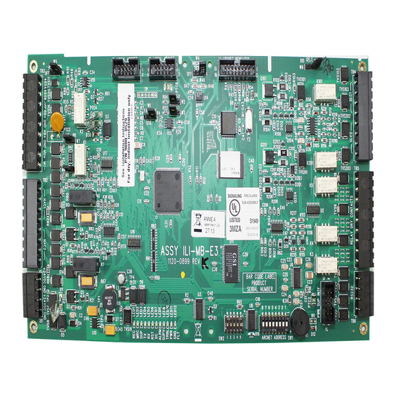
Page 99: Intelligent Loop Interface-Main Board Connections
E3 Series System Connections Intelligent Loop Interface-Main Board Connections 3.2 Intelligent Loop Interface-Main Board Connections Figure 3.2.1 and Figure 3.2.2 illustrate the Intelligent Loop Interface - Main Board (ILI-MB-E3) sub-assembly. Figure 3.2.1 Intelligent Loop Interface-Main Board (ILI-MB-E3) Sub-Assembly Figure 3.2.2 Intelligent Loop Interface-Main Board (ILI-MB-E3) Sub-Assembly E3 Series Installation/Operation Manual —... -
Page 100: 1: Intelligent Loop Interface-Main Board (Ili-Mb-E3) Wiring Connections
Intelligent Loop Interface-Main Board Connections E3 Series System Connections 3.2.1 Intelligent Loop Interface-Main Board (ILI-MB-E3) Wiring Connections Field wiring connections for the ILI-MB-E3 are shown in Table 3.2.1.1. All wiring is Power- limited except the local energy City Box which is non power-limited. Designation Description Comments... - Page 101 E3 Series System Connections Intelligent Loop Interface-Main Board Connections Designation Description Comments TB6-1 RS232 GND To red lead on download cable P/N 75267 RS-232 Download TB6-2 RS232 TxD To black lead on download cable P/N 75267 or Printer Port TB6-3 RS232 Supervision Optional Printer Supervision TB6-4...
-
Page 102: 2: Ili-Mb-E3 Wiring Diagram
Intelligent Loop Interface-Main Board Connections E3 Series System Connections 3.2.2 ILI-MB-E3 Wiring Diagram Figure 3.2.2.1 illustrates the field wiring connections for the ILI-MB-E3 sub-assembly. 4 3 2 1 9 8 7 6 5 4 3 2 1 485A 485B RB+ GND AB+ GND MU+ MU- 5 6 7 8 9 1 2 3 4 1 2 3 4... -
Page 103: Intelligent Loop Interface Xp95-Main Board Connections
E3 Series System Connections Intelligent Loop Interface XP95-Main Board Connections 3.3 Intelligent Loop Interface XP95-Main Board Connections Figure 3.3.1 and Figure 3.3.2 illustrate the Intelligent Loop Interface XP95 - Main Board (ILI95-MB-E3) sub-assembly. Figure 3.3.1 Intelligent Loop Interface XP95-Main Board (ILI95-MB-E3) Sub-Assembly Figure 3.3.2 Intelligent Loop Interface XP95-Main Board (ILI95-MB-E3) Sub-Assembly E3 Series Installation/Operation Manual —... -
Page 104: 1: Intelligent Loop Interface Xp95 - Main Board (Ili95-Mb-E3) Wiring Connections
Intelligent Loop Interface XP95-Main Board Connections E3 Series System Connections 3.3.1 Intelligent Loop Interface XP95 - Main Board (ILI95-MB-E3) Wiring Connections Field wiring connections for the ILI95-MB-E3 is shown in Table 3.3.1.1. All wiring is Power- limited except the local energy City Box that is non power-limited. Designation Description Comments... - Page 105 E3 Series System Connections Intelligent Loop Interface XP95-Main Board Connections Designation Description Comments ARCNET Term OPEN = Normal Operation. SHORT = If the ILI95-MB-E3 is located at the end of the ARCNET bus. RS-485 AUX Terminal OPEN = OFF (Normal Operations) SHORT = ON (RS-485 Termination) W7, W8 Municipal Jumpers...
-
Page 106: 2: Ili95-Mb-E3 Wiring Diagram
Intelligent Loop Interface XP95-Main Board Connections E3 Series System Connections 3.3.2 ILI95-MB-E3 Wiring Diagram Figure 3.3.2.1 illustrates the field wiring connections for the ILI95-MB-E3. 4 3 2 1 9 8 7 6 5 4 3 2 1 485A 485B RB+ GND AB+ GND MU+ MU- 5 6 7 8 9 1 2 3 4 1 2 3 4... -
Page 107: Intelligent Loop Interface - Slave Board (Ili-S-E3) Connections
E3 Series System Connections Intelligent Loop Interface - Slave Board (ILI-S-E3) Connections 3.4 Intelligent Loop Interface - Slave Board (ILI-S-E3) Connections 3.4.1 Signaling Line Circuits The ILI-S-E3 provides two (2), 24 VDC Class A, Style INPUT/CONTROL 6, 7 or Class B, Style 4 signaling line circuits. See MODULE Figure 3.4.1.1 for wiring information. -
Page 108: 2: Intelligent Loop Interface - Slave Board Sub-Assembly
Intelligent Loop Interface - Slave Board (ILI-S-E3) Connections E3 Series System Connections 3.4.2 Intelligent Loop Interface - Slave Board Sub-Assembly Figure 3.4.2.1 and illustrate the Intelligent Loop Interface - Slave board (ILI-S-E3) sub-assembly. Figure 3.4.2.1 ILI-S-E3 Signaling Line Circuit Sub-Assembly Figure 3.4.2.2 ILI-S-E3 Signaling Line Circuit Sub-Assembly E3 Series Installation/Operation Manual —... -
Page 109: 3: Intelligent Loop Interface - Slave Board (Ili-S-E3) Wiring Connections
E3 Series System Connections Intelligent Loop Interface - Slave Board (ILI-S-E3) Connections 3.4.3 Intelligent Loop Interface - Slave Board (ILI-S-E3) Wiring Connections Field wiring connections for the ILI-S-E3 is shown in Table 3.4.3.1. Designation Description Comments TB1-1, TB1-3 +24 V IN +24 VDC Input TB1-2, TB1-4 Common negative from PM-9/PM-9G TB4-2... -
Page 110: 4: Ili-S-E3 Wiring Diagram
Intelligent Loop Interface - Slave Board (ILI-S-E3) Connections E3 Series System Connections 3.4.4 ILI-S-E3 Wiring Diagram Figure 3.4.4.1 illustrates the field wiring connections for the ILI-S-E3 sub-assembly. 4 3 2 1 4 3 2 1 1 2 3 4 Figure 3.4.4.1 ILI-S-E3 Wiring Diagram E3 Series Installation/Operation Manual —... -
Page 111: Intelligent Loop Interface Xp95-Slave Board Connections
E3 Series System Connections Intelligent Loop Interface XP95-Slave Board Connections 3.5 Intelligent Loop Interface XP95-Slave Board Connections 3.5.1 Signaling Line Circuits The ILI95-S-E3 provides two (2),24 VDC Class A, Style 6, 7 or Class B, Style 4 signaling line circuits. INPUT/CO NTRO L See Figure 3.5.1.1 for wiring information. -
Page 112: 2: Intelligent Loop Interface Xp95-Slave Board Sub-Assembly
Intelligent Loop Interface XP95-Slave Board Connections E3 Series System Connections 3.5.2 Intelligent Loop Interface XP95-Slave Board Sub-Assembly Figure 3.5.2.1 and Figure 3.5.2.2 illustrate the Intelligent Loop Interface XP95 - Slave Board (ILI95-S-E3) sub-assembly. Figure 3.5.2.1 ILI95-S-E3 Signaling Line Circuit Sub-Assembly Figure 3.5.2.2 ILI95-S-E3 Signaling Line Circuit Sub-Assembly E3 Series Installation/Operation Manual —... -
Page 113: 3: Intelligent Loop Interface Xp95 - Slave Wiring Connections
E3 Series System Connections Intelligent Loop Interface XP95-Slave Board Connections 3.5.3 Intelligent Loop Interface XP95 - Slave Wiring Connections Table 3.5.3.1 lists the field wiring connections for the ILI95-S-E3. Designation Description Comments TB1-1, TB1-3 +24 V IN +24 VDC Input TB1-2, TB1-4 Common negative from PM-9/PM-9G TB4-2 TB4-1... -
Page 114: 4: Ili95-S-E3 Wiring Diagram
Intelligent Loop Interface XP95-Slave Board Connections E3 Series System Connections 3.5.4 ILI95-S-E3 Wiring Diagram Figure 3.5.4.1 illustrates the field wiring connections for the ILI95-S-E3 sub-assembly. 4 3 2 1 4 3 2 1 1 2 3 4 Figure 3.5.4.1 ILI95-S-E3 Wiring Diagram E3 Series Installation/Operation Manual —... -
Page 115: Ili-E3 And Ili95-E3 Series Programming Address Switch Settings
E3 Series System Connections ILI-E3 and ILI95-E3 Series Programming Address Switch Settings 3.6 ILI-E3 and ILI95-E3 Series Programming Address Switch Settings Figure 3.6.1 illustrates the programming address switch settings for the ILI-E3 and ILI95-E3 Series. Figure 3.6.1 ILI-E3 and ILI95-E3 Series Address Switch Settings E3 Series Installation/Operation Manual —... -
Page 116: Addressable Node Expander (Anx) Connections
Addressable Node Expander (ANX) Connections E3 Series System Connections 3.7 Addressable Node Expander (ANX) Connections The ANX (Addressable Node Expander) is a network interface sub-assembly component of the Gamewell-FCI, E3 Series fire alarm control panel. There are three types of ANX sub-assemblies: ®... -
Page 117: 3: Anx Wiring Requirements
E3 Series System Connections Addressable Node Expander (ANX) Connections 3.7.3 ANX Wiring Requirements Table 3.7.3.1 lists the wiring requirements for the ANX-SR, ANX-MR-FO and ANX-MR-UTP sub-assemblies. Circuit Type Circuit Function Wire Requirements Distance Wire Type* EIA-232 Connects to Printers, Twisted-unshielded 50/15.24 16 AWG (1.30 mm (power-limited) -
Page 118: 6: Addressable Node Expander-Single Ring (Anx-Sr)
Addressable Node Expander (ANX) Connections E3 Series System Connections 3.7.6 Addressable Node Expander-Single Ring (ANX-SR) The Addressable Node Expander Single Ring (ANX-SR) is a basic unit that offers the following features: The unit contains a single E3 Series Local Network connection and one (1) Ethernet interface. •... -
Page 119: Anx-Sr Wiring Connections
E3 Series System Connections Addressable Node Expander (ANX) Connections 3.7.6.1 ANX-SR Wiring Connections Table 3.7.6.1.1 lists the field wiring connections for the ANX-SR sub-assembly. Designation Description Comments TB1-1 +24V +24 VDC Input from the PM-9/PM-9G TB4-1 TB1-2 Common negative from the PM-9/PM-9G TB4-2 TB1-3 +24V TB1-4... -
Page 120: Anx-Sr Wiring Diagram
Addressable Node Expander (ANX) Connections E3 Series System Connections 3.7.6.2 ANX-SR Wiring Diagram Figure 3.7.6.2.1 illustrates the field wiring connections for the ANX-SR sub-assembly. A B A B 1 2 3 4 1 2 3 4 Figure 3.7.6.2.1 ANX-SR Wiring Diagram E3 Series Installation/Operation Manual —... -
Page 121: 7: Addressable Node Expander-Multi-Ring Twisted-Pair (Anx-Mr-Utp)
E3 Series System Connections Addressable Node Expander (ANX) Connections 3.7.7 Addressable Node Expander-Multi-Ring Twisted-Pair (ANX- MR-UTP) The Addressable Node Expander Multi-Ring, Twisted-Pair panel provides the following features: The unit contains a primary and secondary network interface for multi-ring communication. • Offers Ethernet connectivity for configuration or FocalPoint communication. -
Page 122: Anx-Mr-Utp Wiring Connections
Addressable Node Expander (ANX) Connections E3 Series System Connections 3.7.7.1 ANX-MR-UTP Wiring Connections Table 3.7.7.1.1 lists the wiring connections for the ANX-MR-UTP. Designation Description Comments TB1-1 +24V +24 VDC Input from the PM-9/PM-9G TB4-1 TB1-2 Common negative from the PM-9/PM-9G TB4-2 TB1-3 +24V TB1-4... - Page 123 E3 Series System Connections Addressable Node Expander (ANX) Connections 3.7.7.1 ANX-MR-UTP Wiring Connections (Continued) Table 3.7.7.1.2 lists the Primary and Secondary Ring Select Switch settings for the ANX-MR-UTP. The Primary Ring Select Switch sets the network ring number for the Primary Network (uses J2, J4, J5, and/or TB2).
-
Page 124: Anx-Mr-Utp Wiring Diagram
Addressable Node Expander (ANX) Connections E3 Series System Connections 3.7.7.2 ANX-MR-UTP Wiring Diagram Figure 3.7.7.2.1 illustrates the ANX-MR-UTP wiring diagram. 4 3 2 1 A B A B 1 2 3 4 1 2 3 4 Figure 3.7.7.2.1 ANX-MR-UTP Wiring Diagram E3 Series Installation/Operation Manual —... -
Page 125: 8: Addressable Node Expander Multi-Ring Fiber-Optic Pair (Anx-Mr-Fo)
E3 Series System Connections Addressable Node Expander (ANX) Connections 3.7.8 Addressable Node Expander Multi-Ring Fiber-Optic Pair (ANX-MR-FO) The Addressable Node Expander Multi-Ring, Fiber-Optic panel provides the same features as the ANX-MR-UTP with the following additional feature. The ANX-MR-FO network component includes fiber-optic (FO) connectivity on the secondary network connection. -
Page 126: Anx-Mr-Fo Wiring Connections
Addressable Node Expander (ANX) Connections E3 Series System Connections 3.7.8.1 ANX-MR-FO Wiring Connections Table 3.7.8.1.1 lists the wiring connections for the ANX-MR-FO. Designation Description Comments TB1-1 +24V +24 VDC Input from the PM-9/PM-9G TB4-1 TB1-2 Common negative from the PM-9/PM-9G TB4-2 TB1-3 +24V TB1-4... - Page 127 E3 Series System Connections Addressable Node Expander (ANX) Connections 3.7.8.1 ANX-MR-FO Wiring Connections (Continued) Table 3.7.8.1.2 lists the Primary and Secondary Ring Select Switch settings for the ANX-MR-FO sub-assembly. The Primary Ring Select Switch sets the network ring number for the Primary Network (uses J2, J4, J5, and/or TB2).
-
Page 128: Anx-Mr-Fo Wiring Diagram
Addressable Node Expander (ANX) Connections E3 Series System Connections 3.7.8.2 ANX-MR-FO Wiring Diagram Table 3.7.8.2.1 illustrates the ANX-MR-FO wiring diagram. 4 3 2 1 A B A B 1 2 3 4 1 2 3 4 Figure 3.7.8.2.1 ANX-MR-FO Wiring Diagram E3 Series Installation/Operation Manual —... -
Page 129: 9: Anx Programming Address Switch Settings
E3 Series System Connections Addressable Node Expander (ANX) Connections 3.7.9 ANX Programming Address Switch Settings Table 3.7.9.1 illustrates the programming address switch settings for the ANX. Figure 3.7.9.1 ANX Address Switch Settings E3 Series Installation/Operation Manual — P/N 9000-0574:I 11/04/10... -
Page 130: Pm-9/Pm-9G Power Supply Connections
PM-9/PM-9G Power Supply Connections E3 Series System Connections 3.8 PM-9/PM-9G Power Supply Connections The PM-9G electrical specifications are provided in the following sub-sections. 3.8.1 PM-9/PM-9G AC Power Connection The following power source connections must be made in compliance with the National Electrical Code, NFPA 70, Article 760, the applicable NFPA Standards, and according to the requirements of the Authority Having Jurisdiction (AHJ). -
Page 131: 2: Pm-9/Pm-9Gbattery Connections
E3 Series System Connections PM-9/PM-9G Power Supply Connections 3.8.2 PM-9/PM-9GBattery Connections Two (2), twelve volt batteries are connected in series to the PM-9/PM-9G. • • TB3-1 is positive. (For PM-9, see Table 3.8.5.1 and for PM-9G, see Table 3.8.8.1) • TB3-2 is negative. -
Page 132: 4: Pm-9 Power Supply Sub-Assembly
PM-9/PM-9G Power Supply Connections E3 Series System Connections 3.8.4 PM-9 Power Supply Sub-Assembly Figure 3.8.4.1 and Figure 3.8.4.2 illustrate the PM-9 Power Supply sub-assembly. Figure 3.8.4.1 PM-9 Power Supply Sub-Assembly GNDSIG JMP1 Figure 3.8.4.2 PM-9Power Supply E3 Series Installation/Operation Manual — P/N 9000-0574:I 11/04/10... -
Page 133: 5: Pm-9 Power Supply Wiring Connections
E3 Series System Connections PM-9/PM-9G Power Supply Connections 3.8.5 PM-9 Power Supply Wiring Connections Table 3.8.5.1 lists the field wiring connection to the PM-9 Power Supply. Designation Description Comments TB1-1 HOT/BLK Connect to hot, 120VAC, 60Hz - Non Power-limited TB1-2 GND/GRN Connect to ground and isolated earth ground - Non Power-limited TB1-3 NEUT/WHT Connect to neutral 120VAC, 60Hz... -
Page 134: 6: Pm-9 Wiring Diagram
PM-9/PM-9G Power Supply Connections E3 Series System Connections 3.8.6 PM-9 Wiring Diagram Figure 3.8.6.1 illustrates the wiring diagram for the PM-9 sub-assembly. N E U T /W H T G N D /G R N H O T /B L K T B 1 24 V O U T G N D 2 4 V O U T G N D 24 V O U TG N D T B 3... -
Page 135: 7: Pm-9G Power Supply Sub-Assembly
E3 Series System Connections PM-9/PM-9G Power Supply Connections 3.8.7 PM-9G Power Supply Sub-Assembly Figure 3.8.7.1 and Figure 3.8.7.2 illustrate the Power Supply (PM-9G) sub-assembly. Figure 3.8.7.1 Power Supply (PM-9G) Sub-Assembly Figure 3.8.7.2 Power Supply (PM-9G) Sub-Assembly E3 Series Installation/Operation Manual — P/N 9000-0574:I 11/04/10... -
Page 136: 8: Pm-9G Power Supply Wiring Connections
PM-9/PM-9G Power Supply Connections E3 Series System Connections 3.8.8 PM-9G Power Supply Wiring Connections Table 3.8.8.1 list the field wiring connections to the PM-9G Power Supply. Designation Description Comments TB1-1 HOT/BLK Connect to hot, 240 VAC, 50Hz/60Hz - Non Power-limited TB1-2 GND/GRN Connect to ground and isolated earth ground - Non Power-limited... -
Page 137: 9: Pm-9G Wiring Diagram
E3 Series System Connections PM-9/PM-9G Power Supply Connections 3.8.9 PM-9G Wiring Diagram Figure 3.8.9.1 illustrates wiring diagram for the PM-9G sub-assembly. Figure 3.8.9.1 PM-9G Wiring Diagram E3 Series Installation/Operation Manual — P/N 9000-0574:I 11/04/10... -
Page 138: Asm-16 Addressable Switch Connections
ASM-16 Addressable Switch Connections E3 Series System Connections 3.9 ASM-16 Addressable Switch Connections The remote Addressable Switch (ASM-16) is an optional sub-assembly that may be programmed to perform auxiliary switching functions. Connections are made to the following: ILI-MB-E3 or ILI95-MB-E3 TB3 to the ASM-16 TB1 •... -
Page 139: 2: Addressable Switch Sub-Assembly (Asm-16) Sub-Assembly
E3 Series System Connections ASM-16 Addressable Switch Connections 3.9.2 Addressable Switch Sub-Assembly (ASM-16) Sub-Assembly Figure 3.9.2.1 and Figure 3.9.2.2 illustrate the Addressable Switch (ASM-16) sub-assembly. Figure 3.9.2.1 ASM-16 Rear View Figure 3.9.2.2 ASM-16 Front View E3 Series Installation/Operation Manual — P/N 9000-0574:I 11/04/10... -
Page 140: 3: Asm-16 Wiring Connections
ASM-16 Addressable Switch Connections E3 Series System Connections 3.9.3 ASM-16 Wiring Connections For the ASM-16, ANU-48, INI-VG Series, ILI-MB-E3/ILI95-MB-E3, LCD-E3 or remote enclosure installations, use the wiring connections in Table 3.9.3.1, and refer to Notes A-F in Figure 3.9.4.1 for the ribbon cable and hardwire locations. ASM-16 or ANU-48 to ASM-16 or ANU-48 Wiring Designation Description... - Page 141 E3 Series System Connections ASM-16 Addressable Switch Connections Designation Description Designation TB1-2 LCD-7100 TB1-2 ASM-16 or ANU-48 to ASM-16 or ANU-48 Wiring From ASM-16 or ANU-48 RS-485 COM A from previous device/to TB1-3 +24V Single Discrete Wire Connect To: ASM-16 or ANU-48 to ASM-16 or ANU-48 Wiring TB1-3 +24V Single Discrete Wire TB1-3 +24V...
- Page 142 ASM-16 Addressable Switch Connections E3 Series System Connections 3.9.4 ASM-16 or ANU-48 Wiring Connections Figure 3.9.4.1 illustrates the ASM-16 and ANU-48 wiring connections. NOTE A: ASM-16 or ANU-48 to ASM-16 or ANU-48 wiring ASM-16/ANU-48 to ASM-16/ANU-48 RS-485 Connection NOTE C and F: From local INI-VG or LCD-E3 J1 (RS-485 Local) NOTE A:...
-
Page 143: 5: Asm-16 Wiring Diagram
E3 Series System Connections ASM-16 Addressable Switch Connections 3.9.5 ASM-16 Wiring Diagram Figure 3.9.5.1 illustrates the field wiring connections for the ASM-16. J1, J2 AND J3 ARE RS-485 RIBBON CABLE “IN” AND/OR “OUT” CONNECTIONS TO NEXT/PREVIOUS MODULE (NOTE POSITION PIN 1) J3 RS-485 PORT CONNECTIONS - ANU-48 OR J2... -
Page 144: 6: Asm-16 Programming Address Switch Settings
ASM-16 Addressable Switch Connections E3 Series System Connections 3.9.6 ASM-16 Programming Address Switch Settings Figure 3.9.6.1 illustrates the ASM-16 programming address switches. NOTE: Set the first address in the program to switch 32. Set this switch 6 UP when connected to the ILI-MB-E3, ILI95-MB-E3 or ANX. -
Page 145: Digital Alarm Communicator Transmitter (Dact-E3) Connections
E3 Series System Connections Digital Alarm Communicator Transmitter (DACT-E3) Connections 3.10 Digital Alarm Communicator Transmitter (DACT-E3) Connections The DACT-E3 digital communicator transmitter is an optional sub-assembly that features numerous formats for the communication to a central station. It provides the following functions: Line seizure - takes control of the phone lines, disconnecting any premises phones using the same lines •... -
Page 146: 2: Telephone Requirements
Digital Alarm Communicator Transmitter (DACT-E3) Connections E3 Series System Connections 3.10.2 Telephone Requirements • DC Ringer Equivalence Number (REN) = 0.5B • AC Ringer Equivalence Number = 1.3 • Complies with FCC Part 8 The REN is used to determine the quantity of devices that may be connected to the telephone line. Excessive RENs on the telephone line may result in the devices not ringing in response to an incoming call. -
Page 147: 4: Digital Alarm Communicator (Dact-E3) Sub-Assembly
E3 Series System Connections Digital Alarm Communicator Transmitter (DACT-E3) Connections 3.10.4 Digital Alarm Communicator (DACT-E3) Sub-Assembly Figure 3.10.4.1 and Figure 3.10.4.2 illustrate the Digital Alarm Communicator (DACT-E3) sub- assembly. Figure 3.10.4.1 DACT-E3 Sub-Assembly TVS2 TVS1 LED3 LED2 LED1 STAN DBY LIN E2 LIN E1 STATUS STATUS... -
Page 148: 5: Dact-E3 Event Reporting Codes
Digital Alarm Communicator Transmitter (DACT-E3) Connections E3 Series System Connections 3.10.5 DACT-E3 Event Reporting Codes The DACT-E3 can be configured to allow each SLC device to report a unique 3-digit code by selecting the Extended DACT Reporting Feature. To enable this feature, each ILI-MB-E3 and ILI- S-E3 must have V1.3 of the ILI Firmware installed. - Page 149 E3 Series System Connections Digital Alarm Communicator Transmitter (DACT-E3) Connections Event (See Note 2 Contact ID (See Note 3) 3/1 Phone Line 2 Fault Restored LR 2 3 352 [00] (NN) [000] (UUU) 72 Automatic Test (NORMAL) RP 0 1 602 [00] (NN) [000] (UUU) 90 Automatic Test (With Exception) RP 991 1 602 [00] (NN) [991] (UUU) 91...
-
Page 150: Reporting Codes For Non-Slc-Device Events
Digital Alarm Communicator Transmitter (DACT-E3) Connections E3 Series System Connections 3.10.5.1 Reporting Codes for Non-SLC-Device Events For events that do not originate on SLC devices, the DACT-E3 reports extended codes in the range 900-999. These codes are not user-configurable. Figure 3.10.5.1.1 lists the extended codes. Code Event Comment... -
Page 151: 6: Dact-E3 Wiring Connections
E3 Series System Connections Digital Alarm Communicator Transmitter (DACT-E3) Connections 3.10.6 DACT-E3 Wiring Connections Table 3.10.6.1 lists the DACT-E3 wiring connections. Designation Description Comments TB1-1 COM A IN COM A from ILI-MB-E3/ILI95-MB-E3/ANX TB1-2 COM B IN COM B from ILI-MB-E3/ILI95-MB-E3/ANX TB1-3 COM A OUT COM A OUT to other devices... - Page 152 Digital Alarm Communicator Transmitter (DACT-E3) Connections E3 Series System Connections 3.10.6 DACT-E3 Wiring Connections (Continued) Figure 3.10.6.1 illustrates the field wiring connections for the DACT-E3. LED1 LINE 1 STATUS: = LINE 1 INACTIVE = LINE 1 TRANSMITTING DATA FLASHING = LINE 1 FAULT LED2 LINE 2 STATUS: = LINE 2 INACTIVE = LINE 2 TRANSMITTING DATA...
-
Page 153: Repeater (Rpt-E3) Connections
E3 Series System Connections Repeater (RPT-E3) Connections 3.11 Repeater (RPT-E3) Connections The Repeater, RPT-E3 is an optional sub-assembly that provides the interface between the ILI-MB- E3, ILI95-MB-E3, ANX and the Broadband Network. It can also be used with the NGA. The RPT-E3 is available in two versions: •... -
Page 154: 4: Repeater Rpt-E3 Sub-Assembly
Repeater (RPT-E3) Connections E3 Series System Connections 3.11.4 Repeater RPT-E3 Sub-Assembly Figure 3.11.4.1 and Figure 3.11.4.2 illustrate the Repeater (RPT-E3) sub-assembly. Figure 3.11.4.1 Repeater RPT-E3 Sub-Assembly Figure 3.11.4.2 Repeater RPT-E3 Sub-Assembly E3 Series Installation/Operation Manual — P/N 9000-0574:I 11/04/10... -
Page 155: 5: Repeater-E3 Wiring Connections
E3 Series System Connections Repeater (RPT-E3) Connections 3.11.5 Repeater-E3 Wiring Connections Table 3.11.5.1 lists the field wiring connections for the RPT-E3. Designation Description Comments TB1-1 ARCNET PORT 1A Broadband Network (See Note 1) TB1-2 ARCNET PORT 1B Broadband Network (See Note 1) TB1-3 ARCNET PORT 2A Broadband Network (See Note 1) - Page 156 Repeater (RPT-E3) Connections E3 Series System Connections Designation Description Comments Transmitter Light Comm port 1 fiber-optic transmitter drive current Output Control Jumper contributes to drive current when SHORT. Contributes 50% of maximum drive J4, J5 & J6 OPEN - minimum drive, 12.5% of maximum. J4, J5 &...
- Page 157 E3 Series System Connections Repeater (RPT-E3) Connections 3.11.5 Repeater-E3 Wiring Connections (Continued) Table 3.11.5.2 lists the Transmitter Output Power Jumper Settings for the RPT-E3. Port 1 Port 2 Transmit Power OPEN OPEN OPEN OPEN OPEN OPEN 12.5% SHORT OPEN OPEN SHORT OPEN OPEN...
-
Page 158: 6: Rpt-E3 Wiring Diagram
Repeater (RPT-E3) Connections E3 Series System Connections 3.11.6 RPT-E3 Wiring Diagram Figure 3.11.6.1 illustrates the field wiring connections for the RPT-E3. CONNECT TO EARTH GROUND AND J10 CONNECT TO LOCAL ENABLE GROUND DETECTION WHEN ILI-MB-E3, ILI95-MB-E3 OR REMOTELY MOUNTED ANX J4 ARCNET CONNECTOR (NOTE: NOT APPLICABLE WHEN USING (NOTE PIN 1 POSITION) FIBER-OPTIC CONNECTIONS) -
Page 159: Anu-48 Remote Led Driver Connections
E3 Series System Connections ANU-48 Remote LED Driver Connections 3.12 ANU-48 Remote LED Driver Connections The ANU-48 remote LED driver is an optional sub-assembly that provides output to a remote annunciator which may be located up to 3,000 feet from the panel. Up to fifteen (15), additional annunciators can be connected. -
Page 160: 2: Anu-48 Sub-Assembly
ANU-48 Remote LED Driver Connections E3 Series System Connections 3.12.2 ANU-48 Sub-Assembly Figure 3.12.2.1 and Figure 3.12.2.2 illustrate the ANU-48 Remote LED Driver sub-assembly. Figure 3.12.2.1 ANU-48 Sub-Assembly Figure 3.12.2.2 ANU-48 Sub-Assembly E3 Series Installation/Operation Manual — P/N 9000-0574:I 11/04/10... -
Page 161: 3: Anu-48 Wiring Connections
E3 Series System Connections ANU-48 Remote LED Driver Connections 3.12.3 ANU-48 Wiring Connections Table 3.12.3.1 lists the field wiring connections for the ANU-48. NOTE: For ASM-16 or ANU-48 wiring details, Section 3.9.3 ASM-16 or ANU-48 Wiring Connections (Table 3.9.3.1 and Figure 3.9.4.1). Designation Description Comments... -
Page 162: 4: Anu-48 Wiring Diagram
ANU-48 Remote LED Driver Connections E3 Series System Connections 3.12.4 ANU-48 Wiring Diagram Figure 3.12.4.1 illustrates the field wiring connections for the ANU-48. LED1- LED2- LED3- NOTE 1: LED4- LED5- FOR OTHER LED DRIVE LED6- CURRENTS CALCULATE LED7- LED8- REQUIRED CURRENT LED9- LIMIT RESISTOR AND LED10-... -
Page 163: 5: Anu-48 Programming Address Switch Settings
E3 Series System Connections ANU-48 Remote LED Driver Connections 3.12.5 ANU-48 Programming Address Switch Settings The address of the ANU-48 in the system is set via the DIP Switch. Figure 3.12.5.1 illustrates the ANU-48 address DIP switches and the ANU-48 programming address switch settings. For addressing instructions, see the ANU-48 Installation Instructions, P/N 9000-0564. -
Page 164: Lcd-E3 Panel Display Connections
LCD-E3 Panel Display Connections E3 Series System Connections 3.13 LCD-E3 Panel Display Connections The LCD-E3 provides an 80-character display of system events including indicating LEDs and control switches. It may be remotely located via a local RS-485 serial interface. The ILI-MB-E3 or ILI95-MB-E3 will support up to six (6), LCD-E3 displays. -
Page 165: 2: Lcd-E3 Sub-Assembly
E3 Series System Connections LCD-E3 Panel Display Connections 3.13.2 LCD-E3 Sub-Assembly Figure 3.13.2.1 and Figure 3.13.2.2 illustrate the LCD-E3 sub-assembly. Figure 3.13.2.1 LCD-E3 Sub-Assembly Figure 3.13.2.2 LCD-E3 Sub-Assembly E3 Series Installation/Operation Manual — P/N 9000-0574:I 11/04/10... -
Page 166: 3: Lcd-E3 Wiring Connections
LCD-E3 Panel Display Connections E3 Series System Connections 3.13.3 LCD-E3 Wiring Connections Table 3.13.3.1 lists the field wiring connections for the LCD-E3. Designation Description Comments TB1-1 +24V in from ILI-MB-E3 or ILI95-MB-E3 TB3-6 non-resettable B+ TB1-2 ILI-MB-E3 or ILI95-MB-E3 TB3-7 TB1-3 RS-485A RS-485A output from ILI-MB-E3 or ILI95-MB-E3... -
Page 167: 4: Lcd-E3 Wiring Diagram
E3 Series System Connections LCD-E3 Panel Display Connections 3.13.4 LCD-E3 Wiring Diagram Figure 3.13.4.1 illustrates the field wiring connections for the LCD-E3. RS485 KEYPAD DISPLAY Figure 3.13.4.1 LCD-E3 Wiring Diagram E3 Series Installation/Operation Manual — P/N 9000-0574:I 11/04/10... -
Page 168: Lcd-7100 Remote Display Connections
LCD-7100 Remote Display Connections E3 Series System Connections 3.14 LCD-7100 Remote Display Connections The E3 Series System can accommodate up to five (5), Remote Display sub-assemblies via the ® RS-485 serial interface. The LCD-7100 Serial Remote Annunciator provides an 80-character display and function keys for the following: •... -
Page 169: 4: Lcd-7100 Wiring Connections
E3 Series System Connections LCD-7100 Remote Display Connections 3.14.4 LCD-7100 Wiring Connections Table 3.14.4.1 lists the field wiring connections for the LCD-7100. Designation Description Comments TB1-1 COM-A Connect to BSM TB5-2 or ILI-MB-E3 or ILI95-MB-E3 TB3-1 (18 AWG min. twisted-pair) TB1-2 COM B Connect to BSM TB5-1 or ILI-MB-E3 or ILI95-MB-E3 TB3-2... -
Page 170: Standby Battery Calculations
Standby Battery Calculations E3 Series System Connections 3.15 Standby Battery Calculations To determine the standby battery calculations, refer to Table 3.15.1. Total Total Supv. Alarm Supv. Alarm Module Description Current Current Current Current Addressable Node Expander 0.065 A 0.065 A ILI-MB-E3 Intelligent Loop Interface, Main Board 0.081 A... -
Page 171: Analog Sensors
E3 Series System Connections Analog Sensors 3.16 Analog Sensors The E3 Series , signaling line circuits accommodate only Gamewell-FCI approved, UL Listed, ® Factory Mutual Approved analog sensors and bases. Each ILI-E3 Series signaling line circuit can accommodate 159 sensor address points, using Address numbers 01 to 159. The ILI95-E3 Series accommodates 126 sensors/modules, using Address numbers 01 to 126. - Page 172 Analog Sensors E3 Series System Connections Notes E3 Series Installation/Operation Manual — P/N 9000-0574:I 11/04/10...
-
Page 173: Section 4: Programming/Operation Instructions
Section 4: Programming/Operation Instructions 4.1 LED Indicators (LCD-E3) Figure 4.1.1 illustrates the LED indicators. Table 4.1.1 lists the LCD-E3 indicators and a description. AC POWER POWER GROUND ALARM SYSTEM SUPERVISORY SYSTEM FAULT FAULT TROUBLE SILENCED ALARM TROUBLE SIGNAL SYSTEM RESET/ ACKNOWLEDGE ACKNOWLEDGE SILENCE... -
Page 174: Audible/Visual Condition Indications
Audible/Visual Condition Indications Programming/Operation Instructions 4.2 Audible/Visual Condition Indications Table 4.2.1 lists the Audible/Visual Condition Indicators. Condition Audible/Visual Status Indication Alarm Alarm situations are indicated by a one-half second on and one- half second off pattern from the system sounder and the illumination of the red alarm LED. -
Page 175: Switches (Lcd-E3)
Programming/Operation Instructions Switches (LCD-E3) 4.3 Switches (LCD-E3) Figure 4.3.1 illustrates the LCD-E3 switches. Table 4.3.1 lists the LCD-E3 switches and a description. AC POWER POWER GROUND ALARM SYSTEM SUPERVISORY SYSTEM FAULT FAULT TROUBLE SILENCED ALARM TROUBLE SIGNAL SYSTEM RESET/ ACKNOWLEDGE ACKNOWLEDGE SILENCE LAMP TEST... - Page 176 Switches (LCD-E3) Programming/Operation Instructions Notes E3 Series Installation/Operation Manual — P/N 9000-0574:I 11/04/10...
-
Page 177: Section 5: Programming
Section 5: Programming UL Standard 864 Programming Requirements NOTE: NOTICE to users, installers, Authorities Having Jurisdiction (AHJ), and other involved parties: This product incorporates field programmable software. In order for the product to comply with the requirements in the Standard for Control Units and Accessories for Fire Alarm Systems, UL 864 9th Edition, certain programming features or options must be limited to specific values or not used at all as indicated below. -
Page 178: I/O Menu Selection
I/O Menu Selection Programming 5.3 I/O Menu Selection Table 5.3.1 lists the I/O Menu selection and description. Menu Selection Description Output ON/OFF Forces the toggling on or off of a specified output. These outputs can include NAC 1, NAC 2, Municipal Circuit (if present) and any Addressable Control Point. - Page 179 Programming INFO Menu Selection Notes E3 Series Installation/Operation Manual — P/N 9000-0574:I 11/04/10...
-
Page 180: Section 6: Power Up Procedure
Section 6: Power Up Procedure 6.1 General WARNING: POWER UP REQUIREMENTS: PRIOR TO THE APPLICATION OF POWER TO THE SYSTEM, ALL CIRCUITS MUST BE CLEAR OF SHORTS, GROUNDS AND STRAY VOLTAGES. FAILURE TO DO SO COULD CAUSE IRREVERSIBLE DAMAGE TO THE EQUIPMENT. Ensure that all cables and optional modules (if any) are installed and secured per the Installation Instructions. -
Page 181: Section 7: Test And Maintenance
Section 7: Test and Maintenance 7.1 Test The system must be tested periodically in accordance with the requirements of NFPA 72, National Fire Alarm Code and/or applicable state and local codes. 7.2 Maintenance We recommend the replacement of the system standby batteries after three years of service unless otherwise indicated by the battery manufacturer. -
Page 182: Section 8: Power-Limited - Non Power-Limited Wiring
Section 8: Power-Limited – Non Power-Limited Wiring UL Standard 864, (Control Units for Fire Protective Signaling Systems), requires that a minimum of 1/4 inch separation be maintained between power-limited circuits and non power-limited circuits. The control unit is designed so the required separation between these circuits (power- limited vs. -
Page 183: E3 Series Control Panel Circuit Wiring Requirements
Power-Limited – Non Power-Limited Wiring E3 Series Control Panel Circuit Wiring Requirements 8.1 E3 Series Control Panel Circuit Wiring Requirements Table 8.1.1 provides the circuit wiring requirements for the E3 Series control panel. Distance Circuit Type Circuit Function Wire Requirements Typical Wire Type* (feet/meters) Connects to... -
Page 184: E3 Series Power-Limited And Non Power-Limited Diagram
E3 Series Power-Limited and Non Power-Limited Diagram Power-Limited – Non Power-Limited Wiring 8.2 E3 Series Power-Limited and Non Power-Limited Diagram Figure 8.2.1 illustrates the power-limited and non power-limited wiring of the E3 Series control panel. E3 Series Panels DACT-E3 RPT-E3 * Non Power-Limited circuit wiring * Non Power-Limited... - Page 185 Notes E3 Series Installation/Operation Manual — P/N 9000-0574:I 11/04/10...
-
Page 186: Index
Index Event Reporting Codes 147 Digital 144 AC Power Connections PM-9 132 Address Switch Settings ANU-48 162 FPT-GATE-3 Extender Plate 75 ANX 128 ASM-16 143 ILI95-E3 Series 114 Ground Fault Supervision ILI-E3 Series 114 PM-9 132 AM-50 Series Amplifiers 15 PM-9G 135 ANU-48 14 ANX-Addressable Node Expander 12... - Page 187 ASM-16 137 LCD-E3 166 DACT-E3 145 PM-9 133 ILI95-MB-E3 97 PM-9G 136 ILI-MB-E3 97 RPT-E3 157 LCD-7100 167 Wiring Requirements LCD-E3 163 ANX 116 PM-9 130 E3 Series Control Panel 182 PM-9G 130 RPT-E3 152 Standby Battery Calculations 169 ANU-48 169 ANX 169 ASM-16 169 DACT-E3 169...
- Page 188 Manufacturer Warranties and Limitation of Liability Manufacturer Warranties. Subject to the limitations set forth herein, Manufacturer warrants that the Products manufactured by it in its Northford, Connecticut facility and sold by it to its authorized Distributors shall be free, under normal use and service, from defects in material and workmanship for a period of thirty six months (36) months from the date of manufacture (effective Jan.
- Page 189 Gamewell-FCI 12 Clintonville Road Northford, CT 06472-1610 USA 203-484-7161 fax 203-484-7118 www.gamewell-fci.com...
- Page 190 CFI Security Inc. 1845 Northwestern Suite B El Paso, Texas 79912 Ph (915) 778-6061 Fax (915) 778-7046...