Table of Contents
Advertisement
Quick Links
inSTaLLaTion and mainTenance inSTrucTionS
d4120 duct Smoke detector
d4S Sensor component
d4P120 Power board component
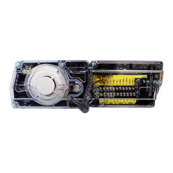
NOTE: The D4120 duct detector consists of D4P120 Power Board component and the D4S Sensor component.
SPecificaTionS
Operating Temperature:
Storage Temperature:
Humidity:
Air Velocity:
D4120 Footprint Dimensions:
D4S/D4P120 Footprint Dimensions: 7.75 in L x 5 in W x 2.5 in D (19.7cm L x 12.7cm W x 6.35cm D)
D4120 Weight:
Electrical
Power supply voltage:
Input capacitance:
Reset Voltage:
Reset Time (with RTS451):
Reset Time (by power down):
Power Up Time:
Alarm response time:
Sensitivity Test:
Current Requirements (Using No Accessories)
Max. standby current
Max. alarm current
CONTACT RATINGS
Alarm initiation contacts (SPST)
Alarm auxiliary contatcs (DPDT)
NOTE: Alarm auxiliary contacts shall not be connected to initiating circuits of control
panels. Use the alarm initiation contact for this purpose.
Supervisory Contacts (SPDT)
TabLe of conTenTS
[1] Limitations of Duct Smoke Detectors. . . . . . . . . . . . . . . . . . . . . . . . . . 1
[2] Exploded View of Duct Smoke Detector Components . . . . . . . . . . . . . 2
[3] General Description . . . . . . . . . . . . . . . . . . . . . . . . . . . . . . . . . . . . . . 2
[4] Contents of Duct Smoke Detector Kit. . . . . . . . . . . . . . . . . . . . . . . . . . 2
[5] Detector Installation . . . . . . . . . . . . . . . . . . . . . . . . . . . . . . . . . . . . . . 2
[6] Sampling Tube Installation . . . . . . . . . . . . . . . . . . . . . . . . . . . . . . . . . 3
[7] Measurement Tests . . . . . . . . . . . . . . . . . . . . . . . . . . . . . . . . . . . . . . . 3
[8] Field Wiring Installation Guidelines. . . . . . . . . . . . . . . . . . . . . . . . . . . 4
[9] Unit Configuration . . . . . . . . . . . . . . . . . . . . . . . . . . . . . . . . . . . . . . . 5
[10] Detector Status Indication . . . . . . . . . . . . . . . . . . . . . . . . . . . . . . . . . 6
[11] Interconnection (Multiple Fan Shut Down). . . . . . . . . . . . . . . . . . . . . 6
[12] Verification of Operation . . . . . . . . . . . . . . . . . . . . . . . . . . . . . . . . . . 6
[13] Detector Cleaning Procedures . . . . . . . . . . . . . . . . . . . . . . . . . . . . . . 7
[14] Sensor replacement. . . . . . . . . . . . . . . . . . . . . . . . . . . . . . . . . . . . . . 7
[15] Optional Accessories. . . . . . . . . . . . . . . . . . . . . . . . . . . . . . . . . . . . . 7
Wiring Diagrams . . . . . . . . . . . . . . . . . . . . . . . . . . . . . . . . . . . . . . . . . . 5-7
Warranty . . . . . . . . . . . . . . . . . . . . . . . . . . . . . . . . . . . . . . . . . . . . . . . . 8
before inSTaLLing
Read the System Sensor Guide for Proper Use of Smoke Detectors in Duct
Applications (A05-1004), which provides information on detector spacing,
placement, zoning, wiring, and special applications. This manual is available
online at www.systemsensor.com. NFPA Standards 72 and 90A should also be
referenced for detailed information.
NOTICE: This manual shall be left with the owner/user of this equipment.
SS-300-000
D4120 & D4S: -4° to 158° F (-20° to 70° C) D4P120: -40° to 158° F (-40° to 70° C)
D4120 & D4S: -22° to 158° F (-30° to 70° C) D4P120: -40° to 158° F (-40° to 70° C)
0% to 95% Relative Humidity Non-condensing
100 to 4000 ft./min. (0.5 to 20.3 m/sec.)
Rectangular - 14.38 in L x 5 in W x 2.5 in D (37cm L x 12.7cm W x 6.36cm D)
Square - 7.75 in L x 9 in W x 2.5 in D (19.7cm L x 22.9cm W x 6.35cm D)
2.5 pounds; 1.14 kg
20-29 VDC
270 µF max.
3.0 VDC min.
.03 to 0.3 sec.
0.6 sec. max.
35 sec. max.
15 sec.
See detector label
21 mA @ 24 VDC
65 mA @ 24 VDC
2.0A @ 30 VDC (resistive)
10A @30 VDC (resistive)
10A @250 VAC (resistive)
1
/
HP @240 VAC
2
1
/
HP @120 VAC
4
2.0A @ 30 VDC (resistive)
2.0A @ 125 VAC (resistive)
24 VAC 50-60-Hz
270 µF max.
2.0 VAC min.
.03 to 0.3 sec.
0.6 sec. max.
35 sec. max.
15 sec.
See detector label
65 mA RMS @ 24VAC 60Hz
135 mA RMS @ 24 VAC 60 Hz
ACCESSORY CURRENT LOADS AT 24 VDC
DEVICE
APA151/APA451
MHR/MHW
RA400Z
RTS451
RTS451KEY
SSK451
NOTE: Any combination of accessories may be used such that the given
accessory loads are: 110mA or less at the Aux output, and 50mA or less
at the Alarm output.
Page
IMPORTANT: This detector must be tested and maintained regularly following
NFPA 72 requirements. The detector should be cleaned at least once a year.
[1] LimiTaTionS of ducT Smoke deTecTorS
The National Fire Protection Association has established that DUCT DETEC-
TORS MUST NOT BE USED AS A SUBSTITUTE FOR OPEN AREA DETECTOR
PROTECTION as a means of providing life safety. Nor are they a substitute for
early warning in a building's regular fire detection system.
System Sensor supports this position and strongly recommends that the user
read NFPA Standards 90A, 72, and 101. The D4120 Air Duct Smoke Detectors
are listed per UL 268A.
This device will not operate without electrical power. Fire situations may
cause an interruption of power. The system safeguards should be discussed
with your local fire protection specialist.
This device will not sense smoke unless the ventilation system is operating
and the cover is installed.
For this detector to function properly, it MUST be installed according to the in-
structions in this manual. Furthermore, the detector MUST be operated within
ALL electrical and environmental specifications listed in this manual. Failure
to comply with these requirements may prevent the detector from activating
when smoke is present in the air duct.
1
3825 Ohio Avenue, St. Charles, Illinois 60174
1-800-SENSOR2, FAX: 630-377-6495
www.systemsensor.com
120 VAC 50-60 Hz
N/A
10 VAC min.
.03 to 0.3 sec.
0.6 sec. max.
35 sec. max.
15 sec.
See detector label
20 mA RMS @ 120 VAC 60 Hz
35 mA RMS @ 120 VAC 60 Hz
STANDBY
TROUBLE
12.5mA
n/a
0mA
n/a
0mA
n/a
0mA
n/a
12mA
n/a
8mA Max.
16mA Max.
WARNING
ALARM
30mA Max.
29mA Max.
12mA Max.
12mA Max.
12mA Max.
40mA Max.
I56-2967-002R
Advertisement
Table of Contents

Related Manuals for Honeywell Gamewell-FCI MS-95


Summary of Contents for Honeywell Gamewell-FCI MS-95
-
Page 1: Table Of Contents
inSTaLLaTion and mainTenance inSTrucTionS d4120 duct Smoke detector 3825 Ohio Avenue, St. Charles, Illinois 60174 d4S Sensor component 1-800-SENSOR2, FAX: 630-377-6495 www.systemsensor.com d4P120 Power board component NOTE: The D4120 duct detector consists of D4P120 Power Board component and the D4S Sensor component. SPecificaTionS Operating Temperature: D4120 &... -
Page 2: Exploded View Of Duct Smoke Detector Components
[2] figure 1. exPLoded VieW of ducT Smoke deTecTor comPonenTS: 4-WIRE EXHAUST TUBE POWER BOARD POWER BOARD MODULE COVER SENSOR MODULE COVER METAL SAMPLING TUBE (sold seperately) SENSOR HEAD MAGNET TEST LOCATION H0549-01 [3] generaL deScriPTion [5.2] deTermine mounTing LocaTion and configuraTion Smoke introduced into an air duct system will be distributed throughout the On ducts wider than 18 inches it is recommended that the detector be entire building. -
Page 3: Sampling Tube Installation
[5.3.2] for Square ToP-oVer-boTTom mounTing ported at the end opposite the duct detector. In ducts wider than 8 feet, configuraTion or d4S SenSor comPonenT mounTing: work must be performed inside the duct to couple the other section of Center punch at (4) target centers: (2) “A” for sampling tubes and (2) “C” for the sampling tube to the section already installed using the inch con- the square configuration mounting tabs as shown on mounting template. -
Page 4: Field Wiring Installation Guidelines
[7.2] LoW fLoW air fLoW TeST uSing dWYer SerieS 607 [8] fieLd Wiring inSTaLLaTion guideLineS differenTiaL PreSSure TranSmiTTer All wiring must be installed in compliance with the National Electrical Code Verify the air speed of the duct using an anemometer. Air speed must be at and the local codes having jurisdiction. -
Page 5: Unit Configuration
figure 7. SYSTem Wiring diagram for 4-Wire ducT Smoke deTecTorS: CAUTION Do not loop wire under terminals when wiring detectors. Break wire runs to provide system supervision of connections. POWER INPUTS (NOTE 1) POWER INPUTS (NOTE 1) 24VAC/DC AUXILIARY CONTACTS AUXILIARY CONTACTS FOR FAN SHUTDOWN, ETC. -
Page 6: Detector Status Indication
[10] deTecTor STaTuS indicaTion [12] VerificaTion of oPeraTion Detector Staus is indicated by the LED sensor, and the correcsponding LED [12.1] fieLd SeLecTabLe SeTTingS on the power board. The power board has two separate LED’s to indicate Verify dip switch settings as per Table 2 on Page 5. the status of each sensor connected to it. -
Page 7: Detector Cleaning Procedures
figure 11. Wiring diagramS for oPTionaL acceSSorieS: CAUTION Canned aerosol simulated smoke (canned smoke agent) formulas will vary by manufacturer. Misuse or overuse to these products may have long term adverse ALARM ALARM effects on the smoke detector. Consult the canned smoke agent manufacturer’s AUX OUT –... -
Page 8: Warranty
SS-300-000 I56-2967-002R ©2008 System Sensor... - Page 9 With the standard priority interrupt feature, the MS-95 will report its condition instantly to the Gamewell-FCI FACP. ® E3 Series is a registered trademark of Honeywell International Inc. ® is a registered trademark of Underwriter’s Laboratories, Inc S281 7300-1703:0136 GAMEWELL-FCI 12 Clintonville Road, Northford, CT 06472-1610 USA •...
- Page 10 Programming Ordering Information To program the MS-95 manual pull station to the address switch settings, set the address DIP switch on the device’s printed circuit board. All other programming is accom- Part Number Description plished at the fire alarm control panel. MS-95 Analog addressable manual pull station MS-95T...
- Page 11 Notification Appliances L-Series, Indoor Strobes and Horn Strobes Indoor Selectable-Output Strobes/Horn Strobes for Ceiling Applications General The L-Series audible visible notification products offer the most versatile and easy-to- use product line of horns, strobes, and horn strobes in the industry. This product includes lower current draws and a modern aesthetic design which reduce installation times and maximize profits.
- Page 12 Architect/Engineer Specifications Synchronization Module General The module shall be a Sync•Circuit model MDL3 listed to UL Standard 464 and shall be approved for fire protective service. The L-Series ceiling-mount strobes and horn strobes shall The module shall synchronize the L-Series strobes at 1 Hz and mount to any of the following: synchronize horns at temporal three.
- Page 13 UL Current Draw Data Table 2 lists the maximum UL Current Draw (mA RMS) allowed for 2-Wire Horn Strobes. 8-17.5 Volts 16-33 Volts DC Input 15cd 30cd 15cd 30cd 75cd 95cd 115cd 150cd 177cd Temporal High Temporal Low Non-Temporal High Non-Temporal Low 3.1K Temp Hi 3.1K Temp Low...
- Page 14 L- Series Dimensions L-Series Dimensions Figure 3 illustrates the dimensions for the ceiling backbox Figure 1 illustrates the dimensions for the ceiling-mount horn surface mount backbox. strobes. 2.47" (62.7 mm) 1.37" (34.8 mm) 6.83" diameter (173 mm) Figure 3 2-Wire Ceiling Mount Horn Strobes with Ceiling Surface Mount Backbox Figure 1 Ceiling-Mount Horn Strobes SL Series Dimensions...
- Page 15 15 – 27°C/60 – 80°F. For more information Learn more about Gamewell-FCI’s L-Series, Indoor Strobes and Horn Strobes and other products available by visiting www.Gamewell-FCI.com Honeywell Gamewell-FCI 12 Clintonville Road Northford, CT 06472-1610 203.484.7161 9021-60928 | C | 03/18 ©2018 Honeywell International Inc. www.honeywell.com...
- Page 16 Addressable Devices PID-95P, PID-95 Point Identification Device General The Gamewell-FCI PID-95P addressable Point Identification Device is the interface between the non-powered, normally-open, dry-contact devices. It is designed to operate with the Gamewell-FCI’s 600 Series and ILI95-E3 Series® of analog addressable fire alarm control panels (FACPs). Point Identification Devices monitor a single Style B circuit, and they are designed to be mounted in an electrical backbox.
- Page 17 Country of origin: U.S.A. main control panel via the analog addressable circuit. The interface device shall be Gamewell-FCI PID-95P or PID- Honeywell Gamewell-FCI 12 Clintonville Road Northford, CT 06472-1610 203.484.7161 CS-2044 | B | 04/19 www.gamewell-fci.com ©2019 Honeywell International Inc.
- Page 18 PSN Series Power Supplies Features • PSN-64 has 6 amps regulated with 4 outputs • PSN-106 has 10 amps regulated with 6 outputs • May be configured as up to three class “A” Style “Z” notification circuits • Two Trouble relays (5A at 30VDC) General System Trouble (programmable for AC delay) Low AC Trouble with optional delay settings •...
- Page 19 PSN Series Power Supplies PSN-106 Wiring Diagram GND FAULT 120/240 VAC Jumper Position DETECT ENABLE 120VAC 50Hz~60Hz 240VAC 50Hz~60Hz Black White Connect to separate Ground unswitched AC circuit Status LED's NAC1 NAC2 NAC3 NAC4 NAC5 NAC6 DC PWR COMM Fuse Factory Installed Interconnect.
- Page 20 PSN Series Power Supplies Engineering Specifications The contractor shall supply and install the Potter PSN power supply. The power supply shall operate on either 120 or 240 VAC input. The panel shall be capable of continuous load power without any degradation to the main supply or the distribution board.
- Page 21 Fire Alarm Con- trol Panel, either through a laptop computer or the control SIGNALING panel operator’s display. (600 Series only). E3 Series® is a registered trademark of Honeywell International Inc. Microsoft® Windows® is a registered trademark of Microsoft® Corporation. Approved 7300-1703:0135 S521...
- Page 22 Mounting Ordering Information The RCE-95 is designed to mount in a standard 4.688" Part Number Description (11.908 cm) electrical backbox. The RCE-95 should be RCE-95 Relay control element device. XP95 mounted in an easily visible location so that the built-in protocol compatible.
- Page 23 12 Clintonville Road, Northford, CT 06472-1610 USA • Tel: (203) 484-7161 • Fax: (203) 484-7118 Specifications are for information only, are not intended for installation purposes, and are subject to change without notice. No responsibility is assumed by Gamewell-FCI for their use. ©2013 by Honeywell International Inc. All rights reserved. www.gamewell-fci.com...
- Page 24 Description (Continued) Specifications, Duct Smoke Detector Accessories (Continued) The RTS2 and RTS2-AOS multi-signaling accessories are RTS151 Remote Test Station designed to operate with the InnovairFlex 4-wire conven- Power Requirements: Alarm LED: 2.8 to 32 VDC, tional duct smoke detectors. These accessories include a 12 mA max.
- Page 25 Accessories Gamewell-FCI provides system flexibility with a variety of accessories, including two remote test stations and several different means of visible and audible system annunciation. As with our duct smoke detectors, all duct smoke detector accessories are UL Listed. Figure 1 RTS151 UL S2522 Figure 2 RTS151KEY UL S2522 Figure 3 APA151 UL S4011 Figure 4 RTS2-AOS UL S2522...