Table of Contents

Related Manuals for GE MAC 5500


Summary of Contents for GE MAC 5500
- Page 1 GE Healthcare MAC™ 5500/MAC™ 5500 HD Resting ECG Analysis System Service Manual Software Version 10 2046275-017G MAC™ 5500/MAC™ 5500 HD Resting ECG Analysis System English © 2011- 2014, 2019 General Electric Company. All Rights Reserved.
- Page 2 Due to continuing product innovation, specifications in this manual are subject to change without notice. MAC, MULTI-LINK, MUSE, MACTRODE, Ultra-Archivist, MobileLink, and 12SL are trademarks owned by GE Medical Systems Information Technologies, Inc., a General Electric Company going to market as GE Healthcare. All other marks are the properties of their respective owners.
- Page 3 Service Manual Language Information (cont'd.) 警告 本維修手冊只提供英文版。 (ZH-TW) • 如果客戶的維修人員有英語以外的其他語言版本需求,則由該客戶負責 提供翻 譯服務。 • 除非您已詳閱本維修手冊並了解其內容,否則切勿嘗試對本設備進行維 修。 • 不重視本警告可能導致維修人員、操作人員或病患因電擊、機械因素或 其他因素 而受到傷害。 UPOZORENJE Ove upute za servisiranje dostupne su samo na engleskom jeziku. (HR) • Ukoliko korisnički servis zahtijeva neki drugi jezik, korisnikova je odgovornost osigurati odgovarajući prijevod.
- Page 4 Ez a szerviz kézikönyv kizárólag angol nyelven érhető el. FIGYELMEZTETÉS • (HU) Ha a vevő szerviz ellátója angoltól eltérő nyelvre tart igényt, akkor a vevő felelőssége a fordítás elkészíttetése. • Ne próbálja elkezdeni használni a berendezést, amíg a szerviz kézikönyvben leírtakat nem értelmezték és értették meg.
- Page 5 Service Manual Language Information (cont'd.) PERINGATAN Manual servis ini hanya tersedia dalam bahasa Inggris. (ID) • Jika penyedia jasa servis pelanggan memerlukan bahasa lain selain dari Bahasa Inggris, merupakan tanggung jawab dari penyedia jasa servis tersebut untuk menyediakan terjemahannya. • Jangan mencoba melakukan servis terhadap perlengkapan kecuali telah membaca dan memahami manual servis ini.
- Page 6 Este manual de assistência técnica só se encontra disponível em inglês. (PT-BR) • Se o serviço de assistência técnica do cliente não for GE, e precisar de outro idioma, será da responsabilidade do cliente fornecer os serviços de tradução. •...
- Page 7 Service Manual Language Information (cont'd.) UPOZORENJE Ovo servisno uputstvo je dostupno samo na engleskom jeziku. (SR) • Ako klijentov serviser zahteva neki drugi jezik, klijent je dužan da obezbedi prevodilačke usluge. • Ne pokušavajte da opravite uređaj ako niste pročitali i razumeli ovo servisno uputstvo. •...
- Page 8 Service Manual Language Information (cont'd.) ЗАСТЕРЕЖЕННЯ Дане керівництво з сервісного обслуговування постачається виключно англійською мовою. (UK) • Якщо сервісний інженер потребує керівництво іншою мовою, користувач зобов'язаний забезпечити послуги перекладача. • Не намагайтеся здійснювати технічне обслуговування даного обладнання, якщо ви не читали, або не зрозуміли інформацію, надану в керівництві з сервісного обслуговування.
-
Page 9: Table Of Contents
Attaching the MAC Device to a Type-S Trolley ..........46 MAC 5500 ST Requirements and Configuration ........47 Blood Pressure Units . - Page 10 Diagrams ....................51 PCB Diagrams..................52 LVDS/LED Display Assembly Diagram .
- Page 11 Inspecting Power Cords ................88 Cleaning and Disinfecting Exterior Surfaces .
- Page 12 Magnetic Card Reader................144 Media ...................... 145 External Modem ..................145 Power ...................... 145 MAC Series Trolley................... 146 Wireless ....................147 Writer...................... 148 Technical Specifications Display ....................149 Computerized Eletrocardiograph............149 Writer...................... 150 Keyboard ....................150 Electrical ....................150 Vectorcardiography ................151 Hi-Res and PHi-Res Signal-Averaged Electrocardiography ....
-
Page 13: Mac™ 5500/Mac™ 5500 Hd
Guidance and Manufacturer's Declaration - Electromagnetic Immunity....................160 Recommended Separation Distances ............. 162 Compliant Cables and Accessories ............163 2046275-017G MAC™ 5500/MAC™ 5500 HD... - Page 14 2046275-017G MAC™ 5500/MAC™ 5500 HD...
-
Page 15: Introduction
ECG data to and from a central ECG cardiovascular information system is optional. The MAC 5500 HD is intended to be used under the direct supervision of a licensed healthcare practitioner, by trained operators in a hospital or medical professional’s facility. -
Page 16: Equipment Symbols
Introduction Equipment Symbols The following symbols may appear on the product or its packaging. Description Symbol Type BF equipment. The acquisition module is protected from defibrillation shocks. Alternating Current Equipotential Charge the battery. The flashing amber LED next to this symbol indicates you must connect the system to AC power to recharge the battery. -
Page 17: Product And Packaging Labeling
Introduction Symbol Description PCT. GOST marking symbolizing conformity with applicable Russian Gosstandart technical and safety standards. USA Only: For use only on or by order of a physician. Product and Packaging Labeling This section identifies the product labels and their locations on the product and packaging. - Page 18 Introduction Refer to the previous illustrations for the locations of the labels identified in the following table. No. Label Description Located on the bottom of the device, this label indicates the device contains mercury and must be disposed of in accordance with state and local laws.
-
Page 19: Equipment Identification
• Regulatory compliance • Country of Origin Equipment Identification Every GE Healthcare device has a product label that identifies the product name, part number, manufacturing information, and unique serial number. This information is required when contacting GE Healthcare for support. - Page 20 Introduction Product Label The product label is laid out in the following format. Depending on the product, the label may vary slightly in format, but it contains the same information. Product Label Format Item Description Product part number Product description Date of manufacture in YYYY-MM format Manufacturer name and address Country of origin...
-
Page 21: Regulatory And Safety Information
Fiscal Week A two-digit code identifying the week the device Manufactured was manufactured. Values range from 01 to 52. GE Healthcare's fiscal weeks correspond to the calendar week. For example, 01 = the first week in January. Product Sequence A four-digit number identifying the order in which this device was manufactured. -
Page 22: Safety Messages
Introduction This manual uses the terms DANGER, WARNING, CAUTION, and NOTICE to point out hazards and to designate a degree or level of seriousness. Familiarize yourself with the following definitions and their significance. Definitions of Safety Conventions Safety Definition Convention DANGER Indicates an imminent hazard, which, if not avoided, will result in death or serious injury. - Page 23 Introduction WARNING: DEFIBRILLATOR PRECAUTIONS — Do not come into contact with patients during defibrillation. Otherwise, serious injury or death could result. Patient signal inputs labeled with the CF and BF symbols with paddles are protected against damage resulting from defibrillation voltages. To ensure proper defibrillation protection, use only the recommended cables and leadwires.
- Page 24 IEC 60601–1–1 medical electrical systems standards. To ensure patient safety, use only parts and accessories manufactured or recommended by GE Healthcare. CAUTION: ACCESSORIES (EQUIPMENT) — The use of accessory equipment that does not comply with the equivalent safety requirements of this equipment may lead to a reduced level of safety of the resulting system.
-
Page 25: Responsibility Of The Manufacturer
If you have questions concerning the disposal of the product, please contact GE Healthcare or its representative. -
Page 26: Responsibility Of The Purchaser/Customer
Additional Assistance GE Healthcare maintains a trained staff of application and technical experts to answer questions and respond to issues and problems that may arise during the installation, maintenance, and use of this system. - Page 27 Introduction Typographical Conventions Convention Description Bold Text Indicates keys on the keyboard, text to enter, or hardware items such as buttons or switches on the equipment. Italicized-Bold Indicates software terms that identify menu items, buttons or options in Text various windows. CTRL+ESC Indicates a keyboard operation.
-
Page 28: Related Documentation
This manual is intended as a supplement to, not a substitute for, thorough product training. If you have not received training on the use of the system, you should request training assistance from GE Healthcare. To see available training, go to the GE Healthcare training Web site (www.gehealthcare.com/training). Select Education>Product Education-Technical>Diagnostic Cardiology. -
Page 29: System Overview
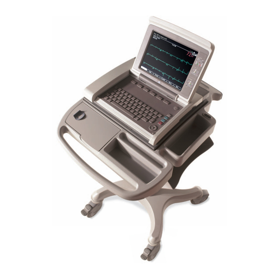
System Overview The MAC 5500/MAC 5500 HD resting ECG analysis system is a 15-lead, 12-channel system with a 10.4 inch (264 mm) diagonal display, active patient cable, battery operation, and late potential electrocardiography. There are also options for communication capabilities. -
Page 30: Back View
System Overview Name Description LAN Port Connect to a LAN cable. LEDs provide information about connection status. • The green LED indicates a good Ethernet link. • The amber LED flashes to indicate network traffic. Keyboard Controls the system and enters data. Back View Name Description... -
Page 31: Back Panel
Name Description Connects to an optional card reader, bar code reader, or PS/2 keyboard for entering patient information. Connects to a GE KISS pump. When using the exercise option, connects to a T2000 treadmill or external blood pressure device. NOTE: Ergoline bicycle ergometers must be connected to both this port and the ANA/TTL port. - Page 32 System Overview Name Description Exchanges ECG data with a MAC system or MUSE CV system via infrared transmission. NOTE: Depending on the age of your system, infrared transmission may not be supported. Card slot Houses a system card for external data storage or to update software.
-
Page 33: Installation
Installation This chapter describes how to assemble the MAC 5500 system and optional accessories on the optional MAC Series Trolley, and it identifies the requirements and configurations for using select devices with the ST option. General Assembly The following sections describe these tasks: •... - Page 34 Locking Caster Swivel Caster Trolley Serial Number NOTE: Because the optional trolley is made by another vendor for GE Healthcare, its serial number format is different from that shown in “Serial Number Format” on page 2046275-017G MAC™ 5500/MAC™ 5500 HD...
-
Page 35: Adjusting Trolley Height
Installation Adjusting Trolley Height The optional MAC Series Trolley can be assembled for one of two heights: 92.07 cm (36.25 inches) or 84.45 cm (33.25 inches). The trolley is normally shipped at the 92.07 cm (36.25 inches) height but can be changed to fit your needs. To change to the lower height, use the following steps. - Page 36 Installation 2046275-017G MAC™ 5500/MAC™ 5500 HD...
-
Page 37: Attaching The Mac Device To The Mac Series Trolley
Installation Attaching the MAC Device to the MAC Series Trolley Use the following procedure to attach the MAC resting ECG analysis system to the trolley assembly. Lock the wheels to prevent the trolley from rolling. Remove the end panel by pulling it out and up. Place the unit on the trolley surface, then slide it forward until the unit is firmly in place and under the tab at the rear of the tray. - Page 38 Installation Secure the MAC unit to the trolley by tightening the three captive screws located under the trolley tray. Replace the end panel by pushing it up and in until you hear a snap. Unlock the wheels to allow free movement of the trolley. 2046275-017G MAC™...
-
Page 39: Attaching The Optional External Modem Kit
Installation Attaching the Optional External Modem Kit An internal modem is standard on the MAC system. If you purchased the optional external modem kit, the modem and its mounting bracket come assembled and ready to attach to the trolley. Use the following instructions. Locate the modem mounting site under the acquisition module support arm at the rear of the trolley. - Page 40 Installation Plug the modem cable into connector port 2 on the MAC unit. Refer to the operator's manual for information on using the modem. 2046275-017G MAC™ 5500/MAC™ 5500 HD...
-
Page 41: Attaching The Magnetic Card Reader
Installation Attaching the Magnetic Card Reader The magnetic card reader and its mounting bracket are assembled and ready to install on the trolley (1). The kit also includes parts for two different trolley styles; disregard and do not use the additional parts (2). Use the following instructions to install the magnetic card reader and its mounting bracket on the trolley. - Page 42 Installation Route the cable around the trolley column towards the rear as shown in the following illustration. 2046275-017G MAC™ 5500/MAC™ 5500 HD...
- Page 43 Installation At the front, hold the cable to the side so it clears the front panel as you replace the panel. Plug the cable connector into port A then replace the back panel. Refer to the operator's manual for information on using the card reader. 2046275-017G MAC™...
-
Page 44: Attaching The Bar Code Reader
Installation Attaching the Bar Code Reader The bar code reader is provided with a cable clamp and mounting bracket. Use the following instructions to attach the bar code reader and its cable mounting bracket on the trolley. Fasten the cable clamp bracket to the underside of the rear handle using a Phillips screw driver and the self tapping screws provided. - Page 45 Installation Fasten the cable and clamp to the clamp bracket and close the device. Verify that there is enough slack to allow free movement of the cable when re-opening the device. 1) Sufficient slack, 2) Insufficient slack Refer to the operator's manual for information on using the bar code reader. 2046275-017G MAC™...
-
Page 46: Attaching The Mac Device To A Type-S Trolley
Installation Attaching the MAC Device to a Type-S Trolley If you have an existing Type-S trolley, use the following instructions to attach the MAC Resting ECG Analysis System. Mount the MAC device to the Type-S trolley as shown in the following illustration. Route a patient cable through the trolley and fasten it with a cable clamp as shown in the following illustration. -
Page 47: Mac 5500 St Requirements And Configuration
MAC 5500 ST Requirements and Configuration The following sections describe the connection and configuration requirements for select external devices that are compatible with the MAC 5500 ST option. The devices are grouped according to device type. • Blood pressure units •... -
Page 48: Treadmills
The MAC 5500 device is compatible with the following treadmills. GE Healthcare Treadmill Model T2000 / T2100 Connection Requirements Use cable PN 2007918-001 (T2000 / T2100) to connect from the MAC 5500 port 1 to the treadmill serial port. Device Configuration... -
Page 49: Bicycle Ergometers
Analog Treadmills Connection Requirements GE Healthcare provides no cables for connecting the MAC 5500 device with analog treadmills. The customer is responsible for making the appropriate cable. Speed and grade signals for controlling analog treadmills are available on pins 2 (Slow Analog Output) and 8 (Fast Analog Output) of the ANA/TTL port. - Page 50 Refer to the ergometer's operator's manual for instructions on configuring the device. MAC 5500 Configuration At the MAC 5500 Main Menu, complete the following: Select Edit Protocol. For each protocol that will be used with this ergometer, set the Test Type to one of the following: •...
-
Page 51: Troubleshooting
Troubleshooting This chapter provides general and specific information to help you isolate service problems. It consists of the following sections: • “Diagrams” • “General Fault Isolation” • “Diagnostic Tests” • “Equipment Problems” • “System Errors” • “Frequently Asked Questions” • “Input and Output Connectors”... -
Page 52: Pcb Diagrams
Troubleshooting PCB Diagrams The following illustrations diagram the structure of the PCB, the connections to and from the PCB, and the connections to the supported display assemblies. PCB Block Diagram 2046275-017G MAC™ 5500/MAC™ 5500 HD... - Page 53 Troubleshooting PCB Connections Diagram 2046275-017G MAC™ 5500/MAC™ 5500 HD...
- Page 54 Troubleshooting Display Connection Details Diagram 2046275-017G MAC™ 5500/MAC™ 5500 HD...
-
Page 55: Lvds/Led Display Assembly Diagram
LVDS/LED Display Assembly Diagram The following illustration diagrams the connections for the LVDS/LED display assembly (2017484–004), and the table that follows it identifies those connections. LVDS/LED Display Assembly Connections Item GE Part Number Description 2001378–006 ASSY DISPLAY CABLE MAC5500 (CMOS) 2062074–001 LVDS/LED LCD PANEL 2034923–002... -
Page 56: General Fault Isolation
Troubleshooting General Fault Isolation Use the following general methods for isolating system faults before starting any detailed troubleshooting procedures. Power-Up Self-Test Power up the device. During power-up, the system conducts a series of internal tests, as shown in the following diagram. If the start screen opens normally, all circuits passed their tests. -
Page 57: Visual Inspection
Troubleshooting Refer to Chapter 5, “Maintenance”, for instructions on checking and replacing the battery. • Is the device receiving AC power? Verify the following: • The power cord is connected to both the AC Mains on the back of the device and an AC outlet. -
Page 58: Diagnostic Tests
Troubleshooting Area Look for the following problems Circuit boards • Moisture, dust, or debris (above and below) • Missing components • Loosely seated components • Burn damage or overheated smell • Improperly seated PCB • Solder problems: cracks, splashes on board, incomplete feedthrough, prior modifications, repairs Ground wires/wiring •... -
Page 59: Loading System Diagnostic Tests
Troubleshooting Loading System Diagnostic Tests Use the following procedure to access the system diagnostic tests. From the resting ECG screen, select Main Menu > More > System Setup. You are prompted for the service password. Type the password and press Enter. The System Setup menu opens. -
Page 60: Display Tests
Type a new password in the System password field and press Enter. Note the new password for future reference. Select Save Setup > To system. Contact GE Healthcare Technical Support and provide them with the customer information, device serial number, and password. Display Tests The system provides two display tests: •... -
Page 61: Speaker Test
Troubleshooting Press any key to display the next test pattern. One of two test patterns is displayed. • If the system color option is enabled, a 32–color test palette is displayed. • If the system color option is not enabled, various grey scale test patterns are displayed. -
Page 62: Writer Tests
Troubleshooting NOTE: The stress keys (1) are available only on the MAC 5500 ST keyboard. These keys will not be available for testing on any other keyboard or system. Pressing the Leads key (2) displays the word Copy if the key is functioning properly. - Page 63 Troubleshooting Skewed or crushed paper indicates a problem with paper cueing. • The triangles and diagonal lines printed on the paper are straight and uniform. Curved or wavering lines could indicate a problem with paper speed, tracking, or cueing. • The lines printed on the paper are clean and unbroken. Gaps, smears, blotches, and other defects indicate a problem with the print head quality.
- Page 64 Troubleshooting After printing the three test patterns, verify the following: • Each test pattern is 250 mm ± 5mm long from start to finish. Use the grids located on the top and bottom of each page for reference. If the printout is out of range, the paper speed is too fast or too slow.
- Page 65 Troubleshooting After the printout completes, check the following: • The pattern begins approximately 13–14 mm from the end of the page. A larger or smaller gap between the end of the page and the pattern could indicate a problem with paper cueing. •...
-
Page 66: Battery Tests
Troubleshooting Continuously Run Out Paper The Continuously Run Out Paper test ejects paper until the paper tray is empty. Manufacturing uses this test to determine how well the unit self-corrects tracking problems. Battery Tests Use the battery tests to monitor the battery's status, discharge rate, and charge rate. Test results are stored in memory and can be printed out. - Page 67 Troubleshooting Turn the AC power to the unit OFF Unplug the unit from AC (mains) power and select OK. Select Battery Discharge Test. The battery begins to discharge. When the battery has fully discharged, the unit will shut off. Reconnect the unit to AC power and turn the unit on. Do one of the following: •...
-
Page 68: Communication Tests
Troubleshooting Monitored information is written to internal memory and includes: • Charge rate (in mAH) • Battery temperature • Battery charge status • To print the test results, proceed to “Print Charge/Discharge Test Results” on page Print Charge/Discharge Test Results The Print Charge/Discharge Test Results prints the results of the Battery Charge Test (page 67) and Battery Discharge Test... - Page 69 Troubleshooting External Modem Test The External Modem Test verifies that the COM2 port can successfully communicate with an optional external modem. NOTE: Although COM 2 is also used to connect the wireless client bridge, this test is designed to check a modem only. It cannot be used to test the wireless client bridge.
-
Page 70: Acquisition Module Test
Troubleshooting Ethernet Module Test The Ethernet Module Test verifies the system can communicate via the Ethernet connection. Select Ethernet Module Test. The Ethernet Module Interrogation window opens and displays one of the following: • If the system can communicate via the Ethernet, the test returns and displays the device IP address, subnet mask, and MAC address information. -
Page 71: Analog I/O Tests
Troubleshooting To run the test, connect all the leads to the RL lead on the patient cable, keep the leads separated and away from any external power supply, and select Acquisition Module Test. NOTE: An effective way to situate the leads correctly is to connect them to a patient simulator that is turned off. -
Page 72: Floppy Drive Tests
When the test is complete, Passed or Failed will be displayed on the screen, depending on the results. Floppy Drive Tests NOTE: The Floppy Drive Test is not applicable for MAC 5500 or MAC 3500 systems. 2046275-017G MAC™ 5500/MAC™ 5500 HD... -
Page 73: Internal Memory Tests
Troubleshooting Internal Memory Tests The Internal Memory Tests check bad blocks and the amount of free memory in the device's internal storage. Select Internal Memory Tests from the System Diagnostics Main Menu. The number of bad blocks and the amount of free memory is displayed. Press any key to continue. -
Page 74: Equipment Problems
Troubleshooting Equipment Problems This section identifies some common problems you may experience with the equipment, lists some possible causes for those problems, and suggests corrective actions. Poor Quality ECGs Poor quality ECGs can be caused by environmental factors, inadequate patient preparation, or hardware failures related to the acquisition module, leadwires, cables, or problems with the unit. -
Page 75: Treadmill/Ergometer Does Not Move
The following table lists symptoms of some common system errors you may experience, identifies possible causes for those errors, and suggests some corrective actions you can take. If the corrective actions do not resolve the errors, contact GE Healthcare Technical Support or an authorized third-party service provider. Symptom... -
Page 76: Frequently Asked Questions
Troubleshooting NOTE: For information about troubleshooting the MobileLink, see the MobileLink Installation Guide. Frequently Asked Questions This section answers frequently asked questions (FAQs) in the following categories: • Maintenance • System Setup • Clinical • Transmission Maintenance The following FAQs relate to the maintenance of the device. How do I save changes to the System Settings? To save changes to the System Settings, do the following: After making a change, return to the System Settings menu by pressing the... -
Page 77: System Setup
This capacity diminishes as the battery ages. NOTE: GE Healthcare recommends the device be plugged into an AC outlet whenever it is not in use. System Setup The following FAQs relate to the setup of the device. For more detailed information on any of these questions, refer to the operator's manual. -
Page 78: Transmission
• To include the MAC 5500 or 12SL Interpretation included on the ECG, enter the number of copies you want in the with column. • To exclude the MAC 5500 from the ECG, enter the number of copies you want in the without column. -
Page 79: Input And Output Connectors
Troubleshooting Why do I lose Referring MD and Technician names when transmitting to the MUSE system? Your MAC system may be transmitting to the SDLC modem on the MUSE system instead of the CSI modem. Check in System Setup to make sure you are transmitting to the MUSE system CSI phone number. -
Page 80: Com2 Pins (J5)
Troubleshooting COM2 Pins (J5) COM2 Pins (J5) Names Diagram Ground +12V Analog Pins (J6) Analog Pins (J6) Names Diagram +12V DC Output 1 TTL Trigger Output Ground Ground DC Output 2 DC Input 1 ECG Output DC Input 2 EXT. VID. Pins (J7) EXT. -
Page 81: Cpu Pcb Input/Output Signals
Troubleshooting EXT. VID. Pins (J7) (cont'd.) Names Diagram Ground Ground Horizontal Sync Vertical Sync CPU PCB Input/Output Signals The following sections detail the input/output signals for the CPU PCB. The pin-by-pin descriptions identify the associated signal names. Battery Pack/Monitor (J2) Battery Pack/Monitor (J2) Signal 18V Battery power... -
Page 82: Keyboard (J8)
Troubleshooting Keyboard (J8) Keyboard (J8) Signal Resistor ground Ground Ground Ground Ground Sense4 Sense2 Sense1 Sense0 Sense3 Sense5 Sense6 Sense7 Drive0 Drive1 Drive2 Drive3 Drive4 Ground Power key Drive5 Drive6 Drive7 Drive8 Drive9 Drive10 LCD (J10) LCD (J10) Signal Ground Clock Hsync Vsync... -
Page 83: Power Supply/Motor (J11)
Troubleshooting LCD (J10) (cont'd.) Signal Ground R0 (LSB) R5 (MSB) Ground G0 (LSB) G5 (MSB) Ground B0 (LSB) B5 (MSB) Ground Data enable 3V Power 3V Power Power Supply/Motor (J11) Power Supply/Motor (J11) Signal Motor Encoder B 5V Power Motor A Motor Encoder A 2046275-017G MAC™... -
Page 84: Thermal Printer (J12)
Troubleshooting Power Supply/Motor (J11) (cont'd.) Signal Ground Motor B 28V Power Ground Battery Charge LED 28V Power Ground Door open detect Ground Thermal Printer (J12) Thermal Printer (J12) Signal Thermal printer power Thermal printer power Thermal printer power Thermal printer power Thermal printer power Thermal printer power Thermal printer power... -
Page 85: Floppy Disk Drive (J13)
Troubleshooting Thermal Printer (J12) (cont'd.) Signal Data strobe Data strobe Data load Data clock Print head temperature Pixel Data Floppy Disk Drive (J13) Floppy Disk Drive (J13) Signal 5V Power Index 5V Power Drive Select 0 5V Power Disk change Motor Select 0 Direction Step... -
Page 86: Acquisition Module (J14)
Troubleshooting Floppy Disk Drive (J13) (cont'd.) Signal Ground Head select Acquisition Module (J14) Acquisition Module (J14) Signal Power Ground TX+ (RS485) TX- (RS485) RX+ (RS485) RX- (RS485) 2046275-017G MAC™ 5500/MAC™ 5500 HD... -
Page 87: Maintenance
Maintenance Regular maintenance, irrespective of usage, is essential to ensure that the equipment will always be functional when required. But even with a regular maintenance regime, the device may eventually need servicing. Therefore, this chapter describes both typical maintenance procedures and standard service procedures. WARNING: MAINTENANCE —... -
Page 88: System Cleaning And Inspection
• Missing or illegible safety-related markings and labels If the power cord shows any of these signs, remove it from service and replace it with the appropriate GE Healthcare replacement part. Repairs or modifications to the power cord are not allowed. - Page 89 Maintenance Cleaning and Disinfecting the Surfaces Proper cleaning and disinfecting prolongs the life of the product. Failure to use the proper cleaning solutions or to follow proper procedures can result in the following: • Damage or corrosion • Product discoloration •...
-
Page 90: Cleaning The Interior
Maintenance • Never use solutions or products that contain any type of Ammonium Chloride such as, but not limited to: • Dimethyl Benzyl Ammonium Chloride • Quaternary Ammonium Chloride solutions • Abrasive cleaners or solvents of any kind • Acetone •... -
Page 91: Cleaning, Disinfecting, And Storing Ecg Cables And Leadwires
Maintenance Cleaning, Disinfecting, and Storing ECG Cables and Leadwires In addition to keeping the MAC system clean and in good repair, it is important to keep the leadwires clean and disinfected. This section provides instructions for cleaning, disinfecting, and storing ECG cables and leadwires to extend their life and protect patients. - Page 92 Maintenance To disinfect, wipe with a soft, lint-free cloth moistened with an appropriate disinfectant. Use the following solutions, as recommended in the APIC Guidelines for Selection and Use of Disinfectants (1996): • Sodium hypochlorite (5.2% household bleach) minimum 1:500 dilution (minimum 100 ppm free chlorine) and maximum 1:10 dilution.
-
Page 93: Cleaning, Disinfecting, And Storing Handheld Devices
Maintenance Cleaning, Disinfecting, and Storing Handheld Devices In addition to keeping the MAC system, leadwires, and cables clean and in good repair, it is important to keep the associated acquisition modules clean and disinfected as well. This section provides instructions for cleaning, disinfecting, and storing the acquisition modules to extend their life and protect patients. - Page 94 Maintenance Cautions • Follow the cleaning instructions exactly. • Wring excess disinfectant from wipe before using. • Never immerse the device, cables, or leadwires in any liquid, as this may corrode metal contacts and affect signal quality. • Do not allow fluid to pool around connection pins. If this happens, blot dry with a soft, lint-free cloth.
-
Page 95: Paper Maintenance
Maintenance Under normal operation, the battery compartment should not require cleaning. If the battery compartment should require cleaning, use the following instructions. CAUTION: DEVICE MALFUNCTION — Cleaning the battery compartment in a manner other than that described in the following procedure may cause the unit to malfunction and void the warranty. -
Page 96: Loading The Paper
Maintenance To set the tray for standard (US Letter) paper, slide the guide toward the front of the device. You are now ready to load your paper. Loading the Paper Use the following instructions to load paper into the MAC system. Refer to the following illustration. -
Page 97: Battery Maintenance
Maintenance Open the writer drawer. Place the pad of paper with the holes on the left. Advance the first sheet of paper. Close the writer drawer securely. Battery Maintenance Proper battery maintenance prolongs the battery life and ensures that the MAC system will operate when needed. - Page 98 Maintenance • When the battery is low • When the battery is completely discharged To determine when the battery is low, use the battery gauge icon that appears in the upper right corner of the system screen. Item Description Battery gauge icon position. Battery fully charged.
-
Page 99: Conditioning The Battery
A deep discharge cycle occurs when the battery is discharged until the system shuts down and then recharged until it is full. GE Healthcare recommends one deep discharge cycle once every three months, but does not recommend over-exercising the battery with multiple deep discharge cycles. -
Page 100: Cable Replacement
Maintenance Cable Replacement During the normal life of the product, it will be necessary to periodically replace the patient cable and leadwire adapters. This section describes those procedures. Replacing Patient Cables Use the following procedure to replace the patient cable. Press the internal access button to open the unit. -
Page 101: Checking Electrical Safety
Maintenance Checking Electrical Safety The device should be checked annually for current leakage and ground continuity. For details, see “Electrical Safety Checks” on page 134. Disassembly/Reassembly Instructions After identifying a component that needs repair or replacement (refer to Chapter “Troubleshooting”), use the procedures described in the following sections to remove and replace the component. - Page 102 Maintenance Lift the device from the trolley. Type-S Trolley To remove the device from the Type-S trolley, perform the steps shown in the following illustration. Modular MAC Trolley To remove the device from the modular MAC trolley, perform the following steps. 2046275-017G MAC™...
-
Page 103: Replacing The Power Supply
Maintenance Remove the bolts connecting the mounting tray to the trolley top. Tilt the rear of the device and mounting tray to a 30° angle. Slide the device and mounting tray toward the back of the trolley to remove them. Remove the screws securing the device to the mounting tray. -
Page 104: Top Cover
Maintenance Lift the power supply to expose the ground wire (2) and wiring harness (3). Remove P2 from J2 on the power supply assembly and the ground wire connection (2) from the power supply chassis. Reverse the previous steps to attach a new power supply. NOTE: Before replacing the screws (1), ensure that the ground wire (2) is routed through the notch in the plastic and not pinched. - Page 105 Maintenance This screw is only visible and accessible with the battery removed. Turn the unit right side up and press the internal access button and raise the top of the unit. Remove the four (4) Torx screws identified in the following illustration. Lower the top of the unit and lock in place.
-
Page 106: Display/Keyboard Assembly
Maintenance Replacing the Top Cover Use the following procedure to replace the top cover. Raise the display to the vertical position. Make sure the bezel surrounding the rear panel connectors is in place. Lower the top cover down around the display and set it in position. Snap the rear of the top cover in place and then, gently pulling on the thin plastic strip at the front of the top cover, position it in place under the keyboard assembly. - Page 107 Maintenance Remove the two Torx screws (3) from the hinge bracket and remove the hinge bracket (2). Remove the screw from the display ground (4) at the left of the hinge rod (5). Slide the display hinge (metal rod) (5) to the left to release it from the right-side mounting detent.
- Page 108 Maintenance Replacing the LVDS Converter Use the following procedure to replace the LVDS PCB assembly required by the AUO-V1 LCD display. See “LVDS Converter PWA Kit (2073125–001)” on page 140 kit information. Remove the display/keyboard assembly from the device. “Removing the Display/Keyboard Assembly” on page 106 for instructions.
- Page 109 Maintenance Disconnect all the cables from the LVDS board on the display assembly. Gently lift the LVDS board from the display assembly and clean any remaining adhesive (1) from the plastic bezel. NOTE: Dispose of the old LVDS board in compliance with all applicable local and federal laws.
- Page 110 Maintenance Position the LVDS board as shown and firmly press until the adhesive pads firmly adhere to the display bezel. Reconnect all the cables to the LVDS. Reattach the display cover. Gently flip over the assembly so the LCD is facing up and reattach the ten screws that secure the assembly to the display cover.
- Page 111 Maintenance Reattach the trim bezel to the display assembly. Reattach the display assembly to the device. “Reassembling the Display/Keyboard Assembly” on page 115 instructions. Replacing the Display Cables Use the following procedure to replace the cables required by the AUO-V1 LCD display. “AUO-V1 LCD Harness Kit (2073088–001)”...
- Page 112 Maintenance Gently flip over the display assembly, so the LCD panel is face down, and remove the display cover. To replace faulty data and power cables, do the following: Disconnect and remove the faulty cable(s). Refer to the following table for a list of the cables and their connection points.
- Page 113 Maintenance To replace a faulty flex cable, do the following: Disconnect the Mainboard to LVDS Power Cable (2034900–004) from the flex cable (1), if it was not disconnected during step 5. Pull the flex cable from the display assembly. Clean the display bezel where the flex cable was affixed. The flex cable uses adhesive to adhere to the bezel.
- Page 114 Maintenance Bend the left side of the flex cable, remove sticker 1, and affix the cable over the two pins on the display bezel (3), as shown in the following photograph. To ensure the adhesive adheres firmly to the bezel, observe the following guidelines: •...
- Page 115 Maintenance Gently flip over the assembly so the LCD is facing up and reattach the ten screws that secure the assembly to the display cover. Reattach the trim bezel to the display assembly. Reattach the display assembly to the device. “Reassembling the Display/Keyboard Assembly”...
-
Page 116: Cpu Board
Maintenance Tilt the display/keyboard assembly to the left and with the roll pin (4) of the hinge (metal rod) parallel to the left hinge base (5), insert the rod into the left hinge base and lower the display/keyboard assembly in place. Slide the tabs (6) into their mounting slots (7) and set the display/keyboard assembly in place. - Page 117 Maintenance Each task is described in the following sections. NOTE: Before you begin, save the current System Setup to an SD card and print a System Setup report. This will be used to restore the system setups after replacement of the CPU board. Removing the CPU Board Use the following procedure to remove the CPU board from the unit.
-
Page 118: Installing The Software
Maintenance Insert the rear bezel into the slot on the back of the unit as shown in the following photograph. Rotate the bezel to the upright position as shown in the following photograph. With the new bezel in place, replace the top cover by reversing the steps described previously. - Page 119 Maintenance Installing the software The MAC software is provided on an SD card. NOTE: Before applying a software update, do the following: • Confirm the update is compatible with the main board in your device. • Updates with boot code version B4 or higher cannot be applied to devices with the –007 main board (P/N 801212-007).
- Page 120 Maintenance Do one of the following: • To cancel the update to the boot code, press any key other than Enter. The following messages are displayed: Boot code not updated. Can update later from service setup. • To update the boot code, press Enter. The following messages are displayed: Programming Primary Boot Programming Over...
- Page 121 Maintenance Connect the device to AC power. Keep the device connected to AC power during the software update. Insert the SD card with the required application software. Before inserting the SD card, confirm that the dummy file update.com is located in the card’s root directory.
- Page 122 Maintenance This is the number that was used when the option codes for this system were generated. The number entered here must match the serial number on the system label. • Printhead resistance This number can be found on the printhead label. •...
-
Page 123: Replacing The Printhead
Maintenance Restoring options Use the following procedure to restore the system options that had been installed on the CPU board that was removed. These options are printed on a label located on the bottom of the paper tray, as shown in the following illustration. NOTE: Use the activator codes shown on the label on your system. -
Page 124: Replacing The Comm Board
Maintenance Disconnect and remove the printhead. Record the resistance value of the new printhead. Connect the new printhead to the ribbon cable. Hold the printhead firmly in place against the two metal tabs on the printhead mounting plate and tighten the two screws. Replace the top cover using the procedure described in “Replacing the Top Cover”... - Page 125 Maintenance Grasp the side edges of the communications board and work it back and forth in the slot as you pull it out along its rails. Insert the new communications board, sliding it onto the rails until it is seated in place.
- Page 126 Maintenance Enter the IP Address, Subnet Mask, and Gateway provided by the network administrator. Enter the Port Number used by the MUSE system. Select Return and press Enter. The Network Setup window closes. On the Basic System menu, select Transmission and press Enter. The Transmission window opens.
-
Page 127: Replacing The Writer Roller/Carriage Assembly
Maintenance Replacing the Writer Roller/Carriage Assembly Use the following procedure to replace the writer roller/carriage assembly. Remove the power supply following the procedure described in “Replacing the Power Supply” on page 103. Inside the power supply compartment, disconnect the cable that connects to the writer assembly. - Page 128 Maintenance Using an Allen wrench, remove the wheel shaft and wheel from the caster. Using an Allen wrench, remove the bolt holding the caster to the trolley. Install the replacement caster on the trolley. NOTE: Ensure that the pins align with the holes on the fixed caster before fastening the caster to the trolley.
-
Page 129: Replacing The Barcode Reader Cable
Maintenance Install the wheel and attach it with the wheel bearing shaft and nut. Using a small mallet, tap the bearing dust covers back in place. Set trolley upright and check the alignment and free movement of casters. Replace the MAC unit. Replacing the Barcode Reader Cable Use the following procedure to replace the cable on a barcode reader. - Page 130 Maintenance Carefully peel back the label (2) so the pin hole is revealed. Insert a paper clip into the pin hole (3) until the cable latch is fully depressed and remove the cable (4). 2046275-017G MAC™ 5500/MAC™ 5500 HD...
-
Page 131: Functional Checkouts
Maintenance Insert the new cable into the handle of the barcode reader until it snaps into place. Fold the label into its original position. Perform all applicable functional checkouts. Refer to “Functional Checkouts” on page 131 for details. Functional Checkouts After replacing a FRU or performing certain tasks, it is necessary to also inspect the unit and perform a series of checks to ensure the unit is functioning properly. - Page 132 Maintenance FRU Repairs (cont'd.) FRU Description Tools Visual Inspection Checkout Procedure(s) 1, 2, 4, 5 3, 7, 8 1, 2, 3, 13 Display Assy 1, 2, 4, 5 3, 8 1 ,2, 3, 15 Keyboard Assy Power Supply Assy 1, 2, 3, 4, 5 8, 9 1 ,2, 3, 21 1, 3, *21...
-
Page 133: Tools
Maintenance Tools ECG Simulator Standard hand tools including a #10 and a #6 Torx Driver Current Leakage Tester Anti-static wrist strap Applicable Service and/or Operator Manual as needed for reference SD Card Visual Inspection Inspect the following for excess wear and or any visual signs of damage. Passed check for defective or broken patient cable/leadwires and out of date electrodes? Discussed electrode placement, skin prep, and patient related requirements with... - Page 134 Maintenance Trolley casters lock successfully? HD displayed on the ECG screen? Diagnostic Tests Battery Status Test meets Battery Current expectation? Display diagnostic test successful? Speaker test successful? Keyboard test successful? Writer diagnostic tests successful? Read/Write Floppy Diagnostic Test successful? (Accurate test does not have to be performed)? External/Internal Modem Test successful? SD Card Test successful?
- Page 135 Maintenance Electrical Safety Checks Step UUT — Condition Result Leakage Current Limits Earth Leakage Current _____ µA 300 µA Forward Polarity Pass/Fail _____ µA 1,000 µA Neutral open, Forward Polarity Pass/Fail _____ µA 1,000 µA Neutral open, Reverse Polarity Pass/Fail _____ µA 300 µA Reverse Polarity...
- Page 136 Maintenance 2046275-017G MAC™ 5500/MAC™ 5500 HD...
-
Page 137: Parts List
Verify part numbers before ordering service parts (field replaceable units). See the tech memo series for this product for changes or additions to this list. For Technical Support parts reference, see PN 2026609-001, MAC 5500 Assembly. 2046275-017G MAC™ 5500/MAC™ 5500 HD... -
Page 138: Barcode Reader
Parts List Barcode Reader The following FRUs relate to the barcode reader option. Barcode Reader FRUs Item Part Number 2031240-001 Kit 2D Barcode Imager MAC5000, English 2031240-002 Kit 2D Barcode Imager MAC5000, German 2031240-003 Kit 2D Barcode Imager MAC5000, French 2031240-004 Kit 2D Barcode Imager MAC5000, Spanish 2031240-005... -
Page 139: Circuit Board
PCB ASSY MAC CPU ROHS 801212-008 NOTE: This board works on MAC 3500 and MAC 5500 devices running MAC software versions 9D and 10B or later. It does not work on MAC 5000 devices. It is loaded with factory software that is not intended for patient use. -
Page 140: Display
FRU DISPLAY AUO V1 MAC5000AAY / MAC5500SCD NOTE: Compatible with the following: • MAC 5500 devices with product codes SCD and SGM • MAC software v9x and v10x • CPU boards 801212-008, 801212-007, and 801212-006 LVDS Converter PWA Kit (2073125–001) The following kit provides the LVDS converter required by the AUO-V1 LCD display (2019106-007). -
Page 141: Auo-V1 Lcd Harness Kit (2073088-001)
Parts List AUO-V1 LCD Harness Kit (2073088–001) The following kit provides the cables required to service the AUO-V1 LCD display (2019106-007). Item Description Part Number Flex Assy MAC Backlight Microsemi 2034923-002 2001378-006 Assy Display Cable MAC5500 2034900-004 MAC5500 Pwr Cable Main Board to LVDS 2059277-001 Assy MAC5500 LCD Data Cable 2059174-001... -
Page 142: Display Plastic Cover Kit (2073124-001)
The following kit provides the plastic housing required to service the AUO-V1 LCD display (2019106-007). Item Description Part Number 2008169–001 Label Kit Lead Placement MAC5500 2017316–001 Trim Display MAC5000 2017315–001 Cover Display MAC5000 2007786–016 Nameplate 30MM GE Logo Label 12SL MAC5000 2008168–001 2046275-017G MAC™ 5500/MAC™ 5500 HD... -
Page 143: Keyboard
Parts List Keyboard The following FRUs relate to the system's keyboards. Keyboard FRUs Item Part Number 421115-101 Keyboard Assembly (Resting), English 421115-201 Keyboard Assembly (Stress), English 421115-102 Keyboard Assembly (Resting), German 421115-202 Keyboard Assembly (Stress), German 421115-103 Keyboard Assembly (Resting), French 421115-203 Keyboard Assembly (Stress), French 421115-104... -
Page 144: Hardware
NOTE: Top Cover and Top Cover Label must be ordered together. 2023119-001 Panel Rear Connector NOTE: This panel supports Infrared and is used on all MAC 5500 units with the product code SCD. 2023119–002 Panel Rear Connector MAC5500 HD NOTE: This panel does not support Infrared and is used on all MAC 5500 HD units with the product code SGM. -
Page 145: Media
Parts List Media The following FRUs relate to media required by, or in support of, the system. Media FRUs Item Part Number 2026831–008 V10B Programmed SD Card 2027268-004 SD card for external storage (512 MB) 2027268-005 SD card for external storage (2GB) NOTE: Supported only by MAC5500 HD units and units upgraded to v10. -
Page 146: Mac Series Trolley
Parts List Power FRUs (cont'd.) Item Part Number 401855-003 Power Cord Italian 10A 250V 8FT 401855-004 Power Cord Israeli 10A 250V 8FT 401855-005 Wire Harness 10A 125V 6.5FT Wire Harness 10A 250V 6.5FT 401855-006 401855-007 Power Cord Swiss 10A 250V 8FT 401855-108 Power Supply Cord, Indian 10A 250V 2.5M 401855-009... -
Page 147: Wireless
Parts List Trolley FRUs (cont'd.) Item Part Number 2024418-001 Trolley Caster Kit (Anti-Static) 2026528-001 CAM 14 Acquisition Holder (for new trolley only) Wireless The following FRUs relate to the system's wireless option. Wireless FRUs Item Part Number 2034529-004 Silex Wireless Serial Server (Global) 2034530-004 Silex Wireless Serial Server Assembly (USA) 2047733-001... -
Page 148: Writer
Parts List Writer The following FRUs relate to the system's thermal writer. Writer FRUs Item Part Number 2029559-001 Printhead 421108-009 Writer Assembly 2031810-002 Universal Service Writer Kit 422396-003 Roller Assembly 2005920-001 Writer Release Button 417565-001 Leaf Spring 416015-001 Gas Cylinder 417467–002 MAC Writer Base Hinge Plastic Front Right 417467–001... -
Page 149: Technical Specifications
Technical Specifications This appendix provides the technical specifications of the MAC system. Display Display Specifications Item Description Type 264mm (10.4 in.) diagonal graphics backlit AM LCD Resolution 640 x 480 pixels, with waveform enhancement Displayed Data Heart rate, patient name, ID, clock, waveforms, lead labels, speed, gain and filter settings, warning messages, prompts and help messages Computerized Eletrocardiograph... -
Page 150: Writer
Technical Specifications Computerized Eletrocardiograph Specifications (cont'd.) Item Description Common Mode >140 dB (123 dB with AC filter disabled) Rejection Input Impedance >10 MΩ @ 10Hz, defibrillator protected Pace Detection 750 µV @ 50 µs duration, Orthogonal LA, LL and V6 Special Acquisition Disconnected lead detection, electrode impedance, AC noise, Functions... -
Page 151: Vectorcardiography
Technical Specifications Electrical Specifications (cont'd.) Item Description Current 0.5A @ 115 VAC, 0.3A @ 240 VAC, typical Frequency 50–60 Hz, ±10% Battery Type User replaceable, 18V @ 3.5 AH ±10%, rechargeable NiMH pack Battery Capacity 100 single-page reports (typical) or 6 hours continuous operation (without printing) Battery Charge Time Approximately 4.5 hrs. -
Page 152: Physical (Without Trolley)
Batteries Disposing of battery by fire or burning will cause the battery to explode. The battery is recyclable. Follow local environmental guidelines concerning disposal and recycling. Batteries may be returned to GE Healthcare for recycling. Device Recyclable Paper discoloration may occur at higher temperatures 2046275-017G MAC™... -
Page 153: Safety
Against Ingress of Liquids Handling of Disposable Use only parts and accessories manufactured or recommended Supplies and Other by GE Healthcare. Follow manufacturer’s instructions for use for Consumables disposable/consumable products. Follow local environmental guidelines concerning the disposal of hazardous materials. Continuous... - Page 154 Technical Specifications 2046275-017G MAC™ 5500/MAC™ 5500 HD...
-
Page 155: Software/Hardware Compatibility
Software/Hardware Compatibility Before ordering software upgrades or replacement CPUs, communication boards, or display assemblies, you need to know which components are compatible. Display Compatibility The following display assemblies are interchangeable and compatible with 801212–006, 801212–007, and 801212–008 circuit boards. However, the components used to construct the display assemblies are not interchangeable. -
Page 156: Circuit Board Compatibility Matrix
Software/Hardware Compatibility Circuit Board Compatibility Matrix Not all supported software versions are compatible with all CPU/Comm board combinations. You must know which software versions are compatible with which CPU and Comm boards before you replace either board or upgrade your software. The following table identifies which software versions are compatible with which CPU/Comm board combinations. -
Page 157: Supported Software Update Paths
Software/Hardware Compatibility Supported Software Update Paths The following table identifies the supported software update paths for each supported main board. Attempting any unlisted update could result in issues either with the update process itself or with the device after the update is complete. Supported Software Update Paths Update Main... - Page 158 Software/Hardware Compatibility 2046275-017G MAC™ 5500/MAC™ 5500 HD...
-
Page 159: Electromagnetic Compatibility
Electromagnetic Compatibility Changes or modification to this system not expressly approved by GE Healthcare could cause EMC issues with this or other equipment. This system is designed and tested to comply with applicable regulation regarding EMC and needs to be installed and put into service according to the following EMC information. -
Page 160: Guidance And Manufacturer's Declaration - Electromagnetic Immunity
40% Ut (60% dip in Ut) 40% Ut (60% dip in Ut) supply input lines environment. If the user of the MAC 5500 for 5 cycles for 5 cycles EN 61000-4-11 requires continued 70% Ut (30% dip in Ut) - Page 161 Electromagnetic Compatibility Immunity Test EN 60601 Test Level Compliance Level Electromagnetic Environment – Guidance Portable and mobile RF communications equipment should not be used closer to any part of the equipment, including cables, than the recommended separation distance calculated from the equation applicable to the frequency of the transmitter.
-
Page 162: Recommended Separation Distances
Electromagnetic Compatibility NOTE: These guidelines may not apply in all situations. Electromagnetic propagation is affected by reflection from structures, objects, and people. Field strengths from fixed transmitters, such as base stations for radio (cellular/cordless) telephones and land mobile radio, AM and FM radio broadcast, and TV broadcast cannot be predicted theoretically with accuracy. -
Page 163: Compliant Cables And Accessories
The following table lists cables, transducers, and other applicable accessories with which GE Healthcare claims EMC compliance. NOTE: Any supplied accessories that do not affect EMC compliance are not included. - Page 164 Electromagnetic Compatibility 2046275-017G MAC™ 5500/MAC™ 5500 HD...
- Page 166 8200 West Tower Avenue Milwaukee, WI 53223 USA Tel: +1 414 355 5000 +1 800 558 7044 (US Only) Fax: +1 414 355 3790 GE Medical Systems Information Technologies, Inc., a General Electric Company, going to market as GE Healthcare. www.gehealthcare.com...