NEC Univerge SV9100 System Hardware Manual
Hide thumbs
Also See for Univerge SV9100:
- Features and specifications (1403 pages) ,
- Programming manual (954 pages) ,
- Manual (766 pages)
Table of Contents
Advertisement
Quick Links
Advertisement
Chapters
Table of Contents

Related Manuals for NEC Univerge SV9100


Summary of Contents for NEC Univerge SV9100
- Page 1 SV 9100 ® System Hardware Manual NDA-31577 ISSUE 3.0...
- Page 3 , NEAX and UNIVERGE are registered trademarks of NEC Corporation and Electra Elite is a registered trademark of NEC America, Inc. Windows is a registered trademark of Microsoft Corporation. AT&T, the AT&T logo and all other AT&T marks are trademarks of AT&T Intellectual Property and/or AT&T affiliated companies.
-
Page 5: Regulatory
The UNIVERGE SV9100 system provides what the customer needs today, and as business expands the system can be expanded to grow as well. The UNIVERGE SV9100 system has a set of manuals that provides all the information necessary to install and support the system. This preface describes these manuals. - Page 6 Chapter 5 – Installing DT Series Digital and IP Multiline Terminals This chapter provides information about the UNIVERGE SV9100 system digital and IP terminals in addition to the single line telephones, cordless telephones and wireless telephones. Chapter 6 – Installing SV9100 Cordless Telephones This chapter provides information regarding cordless telephones that can be used in conjunction with the UNIVERGE SV9100 system.
- Page 7 UNIVERGE SV9100 Programming Manual This manual contains all programming instructions for the SV9100 system. UNIVERGE SV9100 PC Programming Manual This manual describes the operation of the PCPro program for the SV9100 system. This program is a user-friendly Windows application that allows the user to program...
-
Page 9: Table Of Contents
TABLE OF CONTENTS Regulatory Chapter 1 Introduction to SV9100 Section 1 General Information ................. 1-1 Section 2 Equipment List ..................1-5 Chapter 2 SV9100 System Specifications Section 1 General Information ................. 2-1 Section 2 System Block Diagram ................2-1 Section 3 Maximum System Capacities.............. - Page 10 Issue 3.0 Transmission, Network, and Control Specifications...... 2-34 6.6.1 Transmission ................2-34 6.6.2 Network..................2-34 6.6.3 Control ..................2-34 Dialing Specifications ..............2-35 6.7.1 Dial Pulse Address Signaling ............2-35 6.7.2 Dual-Tone Multifrequency (DTMF) Address Signaling ....2-35 6.7.3 External Equipment Connection ..........2-36 6.7.4 Music Source for Music on Hold via Chassis.......
- Page 11 Issue 3.0 2.3.2 Selecting a Permanent MDF Location ........... 3-3 2.3.3 Selecting a Site for Installing the Telephones........ 3-3 Constructing the Main Distribution Frame (MDF)......3-3 Power Failure Transfer..............3-4 Fax CO Branch Connection ............3-5 Section 3 Installing the Chassis ................3-5 Unpacking the Equipment ...............
- Page 12 Issue 3.0 3.5.2 Installing Expansion Blades in the 9.5” Base and Expansion Chassis (Optional) ............... 3-29 3.5.2.1 Connector Pin-Out on the GPZ-BS10/GPZ-BS11 ....3-30 3.5.2.2 Install the GPZ-BS10 Expansion Base Blade in the CHS2UG B-US Controlling Chassis ........3-30 3.5.2.3 Install the GPZ-BS11 Expansion Blade in the CHS2UG B-US Expansion Chassis........3-33 3.5.2.4 Connect the Controlling and Expansion Chassis....3-35...
- Page 13 Issue 3.0 Section 6 Stand Mounting the Chassis..............3-72 Stand Mounting the 19” (CHS2UG-US) Chassis......3-72 6.1.1 CHS2UG-US Chassis Installation..........3-72 6.1.2 Multiple CHS2UG-US Chassis Installation ........3-75 Stand Mounting the 9.5” CHS2UG B Chassis....... 3-78 Section 7 Rack Mounting the Chassis ..............3-82 Rack Mounting the 19”...
- Page 14 Issue 3.0 10.1.2 Install Cooling Fan ..............3-115 Chapter 4 Installing the SV9100 Blades Section 1 General Information................. 4-1 Slot Locations.................. 4-1 Section 2 Installation ....................4-4 Installation and Safety Precautions..........4-4 Installing an Extension or Trunk Blade..........4-5 2.2.1 Installing the Blades ..............
- Page 15 Issue 3.0 3.1.2 Installation..................4-19 3.1.2.1 Battery Installation and Removal ..........4-19 3.1.2.2 GPZ-IPLE Daughter Board Installation ........4-21 3.1.2.3 SD-A1 US/SD-B1 US Installation ...........4-21 3.1.2.4 Background Music (BGM) or Music on Hold (MOH) ....4-21 3.1.3 Switch Settings ................4-22 3.1.4 LED Indications................4-23 3.1.5 Connectors...................
- Page 16 Issue 3.0 4.4.2 Installation..................4-45 4.4.3 Connectors .................. 4-45 GCD-4LCF/GCD-8LCF (4-Port/8-Port Single Line Interface) ..4-47 4.5.1 Description................... 4-47 4.5.2 Installation................... 4-48 4.5.3 LED Indications................4-49 4.5.4 Connectors .................. 4-49 GPZ-4LCF/GPZ-8LCF (4-Port/8-Port SLI Daughter Board)..4-51 4.6.1 Description................... 4-51 4.6.2 Installation..................4-52 4.6.3 Connectors ..................
- Page 17 Issue 3.0 5.3.4 Connectors................... 4-68 GPZ-2BRIA (2 Basic Rate Interface Daughter Board) ....4-69 5.4.1 Description ................... 4-69 5.4.2 Installation..................4-70 5.4.3 Connectors................... 4-70 GCD-4DIOPA (DID/OPX Interface)..........4-72 5.5.1 Description ................... 4-72 5.5.2 Installation..................4-73 5.5.3 LED Indications................4-73 5.5.4 Connectors................... 4-74 GCD-PRTA (PRI/T1 Interface) ............
- Page 18 Issue 3.0 6.1.4 Connectors .................. 4-90 6.1.4.1 RS-232 Interface..............4-90 6.1.4.2 DB9 to 6-pin Modular RS-232 Adapter ........4-91 6.1.4.3 RS-232 Serial Cable (DTE) ............4-91 6.1.4.4 RS-232 Serial Cable (DCE) ............4-92 6.1.4.5 USB Interface .................4-92 6.1.4.6 VGA Display Interface ............4-92 6.1.4.7 10 Base-T/100 Base-TX Ethernet Interface......4-92 GCD-PVAA (Packet Voice Application) ........
- Page 19 Issue 3.0 6.5.2.4 Port Number Determination ..........4-107 6.5.2.5 Unmanaged Switch Functions ..........4-108 6.5.3 LED Indications................4-108 6.5.4 Connectors................. 4-108 GCD-SVR2 (Server Blade)............4-109 6.6.1 Description ................. 4-109 6.6.2 Installation.................. 4-110 6.6.3 LED Indications................4-110 6.6.3.1 Power LED................4-110 6.6.3.2 Application1 and Application 2 LEDs ........4-110 6.6.3.3 SSD Active LED..............4-110 6.6.4 Connectors.................
- Page 20 Issue 3.0 2.1.6 DTL-12D-1 (BK)/(WH) TEL............5-19 2.1.7 DTL-12PA-1 (BK) TEL ..............5-20 2.1.8 DTL-24D-1 (BK)/(WH) TEL............5-21 2.1.9 DTL-32D-1 (BK)/(WH) TEL............5-22 DT400 Series Digital Multiline Terminals ........5-23 2.2.1 DTZ-2E-3 (BK) TEL ..............5-23 2.2.2 DTZ-6DE-3 (BK) TEL..............5-24 2.2.3 DTZ-12D-3 (BK)/(WH) TEL............
- Page 21 Issue 3.0 Section 4 Install Multiline Terminals ..............5-45 Connecting the DT300/DT400 Series Multiline Terminal to the System ..................5-45 4.1.1 Connecting the Handset .............. 5-45 4.1.1.1 Handset Connection DT300 ...........5-45 4.1.1.2 Handset Connection DT400 ...........5-45 4.1.2 Connecting the Line Cord ............5-46 4.1.2.1 Line Cord Connection DT300 ..........5-46 4.1.2.2...
- Page 22 Issue 3.0 5.2.3 8LKI (LD)-L UNIT (BK/WH)............5-68 5.2.3.1 Installing the 8LKI (LD)-L UNIT..........5-68 5.2.4 Installing Line Key Kit (12LK-L KIT)..........5-71 5.2.4.1 Installing the 12LK-L KIT ............5-72 5.2.4.2 Configuring the Digital Telephone for the Correct Number of Line Keys ................5-76 5.2.4.3 Configuring the IP Telephone for the Correct Number of Line Keys ................5-76...
- Page 23 Issue 3.0 UTR-1-1 USB Handset..............5-106 6.3.1 Handset Connection ..............5-106 6.3.2 USB Connection ................ 5-106 6.3.3 Wall Mounting ................5-107 Section 7 UT880 IP Telephone ................5-108 Powering the UT880..............5-108 Updating the UT880 System Firmware ........5-108 UT880 Platform Information ............5-108 UT880 (Front View) ..............
- Page 24 Issue 3.0 3.1.3 Manual Registration..............6-18 3.1.4 Registering to a Different Base............ 6-19 Installing the Repeater ..............6-19 3.2.1 Finding the Right Location............6-19 3.2.2 Map the Base Coverage Area ............. 6-20 3.2.3 Test the Location ................. 6-20 3.2.4 Installing the Repeater..............6-21 3.2.5 Multiple Repeater Systems............
- Page 25 Cordless Phone Headset (M175)......6-45 term ® 6.2.3 NEC D NEC Polaris SupraPlus™ ........6-45 term ® 6.2.4 NEC D NEC Polaris Mirage ® ..........6-46 term ® 6.2.5 NEC D NEC Polaris TriStar ® ..........6-46 term ® 6.2.6 NEC D NEC Polaris Encore ®...
- Page 26 Powering on the Handset.............. 7-23 Chapter 8 Installing SV9100 Conference Solutions Section 1 General Description................. 8-1 Section 2 NEC SIP Conference Max................ 8-1 Installation ..................8-1 Connecting and Charging the Batteries .......... 8-3 Keypad Functions ................8-3 Programming Options ..............8-4 Compliance ..................
- Page 27 Issue 3.0 Section 2 PGD(2)-U10 ADP..................9-1 Using a PGD(2)-U10 ADP............... 9-1 LED Indications ................9-2 Setting up PGD(2)-U10 ADP Connections........9-2 Section 3 Background Music ................. 9-10 Installing Background Music............9-10 Section 4 Door Box ....................9-10 Installing a Door Box ..............9-10 Section 5 External Paging ..................
- Page 28 Issue 3.0 10.1.1 Removing the Faceplate.............. 9-25 term ® Section 11 D Voice Security Recorder (VSR)..........9-26 term 11.1 Voice Security Recorder (VSR) ........... 9-26 11.2 PC Compatibility................9-26 11.2.1 Connection Configuration ............9-26 11.2.2 Connectors .................. 9-27 11.3 Installation ..................9-27 11.3.1 VSR Application Software ............
- Page 29 11.7.3.1 Install VSR Reporter Pro ............9-59 11.7.3.2 Register VSR Reporter Pro ............9-59 Section 12 IP/Digital Call Logging ................9-60 12.1 NEC 1-Port Digital Logging Unit............ 9-60 12.1.1 PC Compatibility ................9-61 12.1.2 Connection Configuration ............9-61 12.1.3 Connectors................... 9-61 12.1.4 Installation..................9-62 12.1.5 Call Logging Application Software ..........
- Page 30 12.3.1.3 Screen Resolution ..............9-94 12.3.1.4 Is Microsoft.Net Framework 2.0 Installed? ......9-94 12.4 NEC IP/Digital Player Installation..........9-95 12.4.1 Installing the NEC IP/Digital Player ..........9-95 12.5 NEC IP/Digital Manager Installation..........9-101 12.5.1 Installing the NEC IP/Digital Manager ........9-103 12.5.2 Install Call Manager License............9-108 12.5.2.1 License Manager System .............9-108...
- Page 31 Issue 3.0 12.6 NEC IP/Digital Reporter Pro Installation........9-111 12.6.1 Installing the IP/Digital Reporter Pro.......... 9-113 12.6.2 Install Reporter Pro Licensing............ 9-118 12.6.2.1 License Manager System .............9-118 12.6.2.2 USB Dongle ................9-118 Section 13 Telephone Adapters................9-119 13.1 Using Adapters................9-119 13.2...
- Page 32 Issue 3.0 13.7.2.2 Security.................9-154 13.7.2.3 VoIP Traversal ..............9-154 13.7.3 IP6-L Adapter Installation and Configuration ......9-155 13.7.3.1 Log into IP6-L Adapter Configuration Screen .......9-155 13.7.3.2 Security.................9-156 Section 14 Power Failure Telephones ..............9-156 14.1 Power Failure ................9-156 14.2 Connector Pin-Outs on COIU Blade for Power Failure Circuits ..................
- Page 33 Issue 3.0 16.5.3 Installing the IP Video Doorphone ..........9-177 16.5.4 Installing the IP Video Doorphone Using a Wall Mount Bracket (IP3WW-CDH BRACKET SET) ........9-178 16.5.5 Installing the IP Video Doorphone Using a Wall Cover Set (IP3WW-CDH WALL COVER SET) ........9-179 System Hardware Manual...
- Page 34 Issue 3.0 xxvi Table of Contents...
- Page 35 LIST OF FIGURES Chapter 1 Introduction to SV9100 Figure 1-1 Simplified SV9100 System (9.5” Gateway and Base) Connectivity .......1-2 Figure 1-2 Simplified SV9100 System (9.5” Base and Expansion) Connectivity ......1-3 Figure 1-3 Simplified SV9100 System (19”) Connectivity ...............1-3 Chapter 2 SV9100 System Specifications Figure 2-1 SV9100 System Block Diagram ..................2-4 Figure 2-2...
- Page 36 Issue 3.0 Figure 3-19 GPZ-BS11 Installed (Cover Closed) ................3-16 Figure 3-20 19” Expansion Chassis Interface Units ............... 3-17 Figure 3-21 System Expansion Cabling ..................3-18 Figure 3-22 Chassis Grounding Lug ....................3-19 Figure 3-23 19” Chassis Grounding Lug (Multiple-Chassis) ............3-20 Figure 3-24 Install the AC Power Cord ...................
- Page 37 Issue 3.0 Figure 3-53 Wall Mount Positioning for 9.5” Base/Expansion Chassis ...........3-46 Figure 3-54 Wall Mount Spacing Guide (9.5” Chassis) ..............3-47 Figure 3-55 Anchor Bolt from Wall (9.5” Chassis) ................3-48 Figure 3-56 Align Bracket on Wall (9.5” Chassis) ................3-48 Figure 3-57 Install Upper Bracket (9.5”...
- Page 38 Issue 3.0 Figure 3-87 Install Rubber Feet for Multiple Chassis ..............3-71 Figure 3-88 Install Metal Brackets with Screws ................3-71 Figure 3-89 Assemble Stand Mount with Screws ................3-72 Figure 3-90 Secure CHS2UG-US Chassis to CHS2UG STAND KIT (K) with Screws ....3-73 Figure 3-91 Secure Stand Mount to Floor with Screws ..............
- Page 39 Issue 3.0 Figure 3-121 Removing Battery Tray Cover ..................3-95 Figure 3-122 Removing Battery Tray Bracket ...................3-96 Figure 3-123 Battery Cable Connection Guide .................3-96 Figure 3-124 Installing Battery Connection Cable ................3-97 Figure 3-125 Connecting Battery Cables ..................3-98 Figure 3-126 Installing Cover Battery ....................3-98 Figure 3-127 Removing Fan Access Panel ..................3-99 Figure 3-128...
- Page 40 Issue 3.0 Chapter 4 Installing the SV9100 Blades Figure 4-1 19” Chassis CPU and Expansion Slot Locations ............4-2 Figure 4-2 9.5” Gateway Chassis CPU Location ................4-2 Figure 4-3 9.5” Base and Expansion Chassis CPU Location ............4-3 Figure 4-4 Inserting Blades in the 19”...
- Page 41 Issue 3.0 Figure 4-34 Install the SO-DIMM Memory ..................4-89 Figure 4-35 Install the Compact Flash Drive ...................4-89 Figure 4-36 GCD-VM00 DB9 to 6-Pin Modular RS-232 Adapter ............4-91 Figure 4-37 GCD-VM00 RS-232 Serial Cable (DTE) ..............4-91 Figure 4-38 GCD-VM00 RS-232 Serial Cable (DCE) ..............4-92 Figure 4-39 GCD-PVAA Blade ......................4-94 Figure 4-40...
- Page 42 Issue 3.0 Figure 5-21 ITL-12DG-3 TEL ......................5-34 Figure 5-22 ITL-12PA-1 TEL ......................5-35 Figure 5-23 ITL-24D-1 TEL ......................5-36 Figure 5-24 ITL-32D-1 TEL ......................5-37 Figure 5-25 ITL-320C-1 TEL/ITL-320C-2 TEL ................5-38 Figure 5-26 ITZ-8LD-3 TEL ......................5-39 Figure 5-27 ITZ-12D-3 TEL ......................
- Page 43 Issue 3.0 Figure 5-55 Wall Mounting Base on Wall Plate ................5-59 Figure 5-56 Wall Mounted Multiline Terminal ..................5-59 Figure 5-57 8LK-L UNIT ........................5-62 Figure 5-58 Remove Side Panel from Multiline Terminal ..............5-62 Figure 5-59 Securing the 8LK-L UNIT with Screws .................5-63 Figure 5-60 Install the 8LK-L UNIT Cable ..................5-63 Figure 5-61...
- Page 44 Issue 3.0 Figure 5-89 Remove the Ten Key Kit ..................... 5-82 Figure 5-90 Install the Ten Key Kit ....................5-82 Figure 5-91 Secure the Ten Key Kit ....................5-83 Figure 5-92 Install Plastic Panels ....................5-83 Figure 5-93 Sticker-Braille-L KIT (Sheet 1) ..................5-86 Figure 5-94 Sticker-Braille-L KIT (Sheet 2) ..................
- Page 45 Issue 3.0 Figure 5-123 Plug Cable into Wall ....................5-104 Figure 5-124 Plugging Cable into DCL-60-1/DCZ-60-2 CONSOLE ..........5-104 Figure 5-125 ITL / DTL PTM Handset .....................5-105 Figure 5-126 ITL / DTL PTT Handset ....................5-105 Figure 5-127 Installing the UTR-1-1 USB Handset Cable ...............5-106 Figure 5-128 Installing the UTR-1-1 USB Handset to a PC ............5-106 Figure 5-129...
- Page 46 Issue 3.0 Figure 6-24 Six Repeaters Attached to Base ................. 6-16 Figure 6-25 Daisy-Chain Layout ..................... 6-16 Figure 6-26 Base Coverage Area ....................6-20 Figure 6-27 Incorrect Installation ....................6-22 Figure 6-28 Base Coverage Area ....................6-22 Figure 6-29 Daisy-Chain Layout ..................... 6-23 Figure 6-30 Bluetooth Cradle Controls and Indicators ..............
- Page 47 USB Wireless Headset (CS50-USB) ..............6-42 Figure 6-59 Cordless Headset (MX250) ..................6-44 Figure 6-60 Cordless Headset (M175) ....................6-45 Figure 6-61 NEC Polaris Supraplus ....................6-45 Figure 6-62 NEC Polaris Mirage .....................6-46 Figure 6-63 NEC Polaris TriStar ......................6-46 Figure 6-64 NEC Polaris Encore .....................6-47...
- Page 48 Issue 3.0 Chapter 8 Installing SV9100 Conference Solutions Figure 8-1 NEC SIP Conference Installation .................. 8-2 Figure 8-2 Install Additional NEC SIP Conference Units ..............8-2 Chapter 9 Installing SV9100 Optional Equipment Figure 9-1 PGD(2)-U10 ADP ......................9-2 Figure 9-2 Remove Cover from PGD(2)-U10 ADP .................
- Page 49 Options Tab .........................9-69 Figure 9-55 Manage Calls at Completion ..................9-71 Figure 9-56 File Management Tab ....................9-71 Figure 9-57 NEC Options for Additional Adjustments ..............9-72 Figure 9-58 Customizing Application to Meet Requirements ............9-73 Figure 9-59 Digital Call Logger Connection ..................9-74 Figure 9-60 Digital Logging Unit Connection Configuration ............9-75...
- Page 50 USB Key Error – Call Manager ................. 9-109 term Figure 9-91 VSR Call Manager – Select USB Dongle ............9-110 Figure 9-92 NEC IP/VSR Reporter Pro ..................9-111 Figure 9-93 VSR Reporter Pro ..................... 9-112 term Figure 9-94 VSR Reporter Pro – Welcome Screen ............. 9-113...
- Page 51 Figure 9-101 In-Line Power Adapter ....................9-120 Figure 9-102 In-Line Power Adapter Switch Settings ..............9-121 Figure 9-103 NEC Terminal Connection to an IEEE 802.3af PoE Switch ........9-122 Figure 9-104 ADA-L UNIT .......................9-123 Figure 9-105 Separate Tilt Leg from Leg Support ................9-125 Figure 9-106 Bottom Option Interface Knockout ................9-126...
- Page 52 Issue 3.0 Figure 9-132 Remove Legs From Multiline Terminal ..............9-143 Figure 9-133 Attach the LAN Cable ....................9-144 Figure 9-134 Attach the DC Power Cable ..................9-144 Figure 9-135 Align Bracket with Terminal ..................9-145 Figure 9-136 Pass Cabling Through Bracket .................. 9-145 Figure 9-137 Secure Bracket to Terminal ..................
- Page 53 Issue 3.0 Figure 9-166 Shining on Doorphone ....................9-170 Figure 9-167 Lighting Equipment ....................9-171 Figure 9-168 C and NC Terminal Connections ................9-172 Figure 9-169 C and NO Terminal Connections ................9-172 Figure 9-170 2-Wire Connections ....................9-173 Figure 9-171 Camera Angle Adjustment Lever ................9-175 Figure 9-172 Angle Adjustment Stand ....................9-176 Figure 9-173...
- Page 54 Issue 3.0 xliv List of Figures...
- Page 55 LIST OF TABLES Regulatory Table R-1 Battery Types and Quantities for Chassis and Blades ..........R-7 Chapter 1 Introduction to SV9100 Table 1-1 Chassis Equipment List ....................1-5 Table 1-2 Chassis Installation Equipment List ................1-5 Table 1-4 Blade Equipment List ....................1-6 Table 1-3 Battery Mount Equipment List ..................
- Page 56 Issue 3.0 Table 2-7 SV9100 Maximum 9.5” Base and Expansion System Capacities – Blades ..... 2-14 Table 2-8 Daughter Board Combinations ................. 2-17 Table 2-9 License Information ....................2-18 Table 2-10 Board Power Factor Chart ..................2-22 Table 2-11 Maximum Number of Packages Installed ..............2-22 Table 2-12 Terminal Power Factor .....................
- Page 57 Issue 3.0 Table 4-2 Adding Daughter Board to Chassis Example ............. 4-7 Table 4-3 Trunk Blade Installation Order Example ..............4-8 Table 4-4 Default Port Settings ....................4-11 Table 4-5 SRAM Data Types ....................4-20 Table 4-6 GCD-CP10 Switch Settings ..................4-22 Table 4-7 GCD-CP10 Switch 4/6 Settings ................
- Page 58 Issue 3.0 Table 4-31 GCD-4DIOPA RJ-61 Cable Connector Pin-Outs ............. 4-74 Table 4-32 GCD-PRTA LED Indications ..................4-78 Table 4-33 T1 LED Indications ....................4-79 Table 4-34 GCD-PRTA RJ-45 Cable Connector Pin-Outs ............4-80 Table 4-35 GCD-PRTA RJ48C Connector Pin-outs ..............4-80 Table 4-36 GCD-4ODTA LED Indications ..................
- Page 59 Issue 3.0 Table 5-11 Terminal and Optional Equipment Compatibility (DT400/DT800) ......5-13 Table 5-12 Connectivity of Options (DT300/DT700) ..............5-60 Table 5-13 Connectivity of Options (DT400/DT800) ..............5-61 Table 5-14 Line Key Type ......................5-76 Table 5-15 Ten Key Kit Type ...................... 5-76 Table 5-16 Line Key Kit Type .....................
- Page 60 Issue 3.0 Chapter 9 Installing SV9100 Optional Equipment Table 9-1 PGD(2)-U10 ADP LED Indications ................9-2 Table 9-2 PGD(2)-U10 ADP S3 – S6 Jumper Settings .............. 9-4 Table 9-3 ADA-L UNIT Switch Settings .................. 9-124 Table 9-4 DT330 Compatibility Settings ................. 9-124 Table 9-5 RJ-61 Cable Connector ..................
-
Page 61: General Information
The telephone company may make changes in its technical operations and procedures. When such changes affect the compatibility or use of the UNIVERGE SV9100 system, the telephone company is required to give adequate notice of the changes in order for you to maintain uninterrupted service. - Page 62 If equipment malfunctions, all repairs must be performed by an authorized agent of NEC Corporation of America. The user requiring service is responsible for reporting the need for service to an NEC...
- Page 63 The consumer/purchaser/supplier instructions accompanying this equipment and/or software features must contain the following notice: The software contained in the UNIVERGE SV9100 to allow user access to the network must be upgraded to recognize newly established network area codes and exchange codes as they are placed into service.
- Page 64 Issue 3.0 Routed to a recorded announcement that can be administered by the Customer Premise Equipment (CPE) user. Routed to a dial prompt. This equipment returns answer supervision on all DID calls forwarded to the Public Switched Telephone Network (PSTN).
- Page 65 Issue 3.0 HEARING AID COMPATIBILITY NEC Multiline Terminals and NEC Single Line Telephones that are provided for this system are hearing aid compatible. The manufacturer of other Single Line Telephones for use with the system must provide notice of hearing aid compatibility to comply with FCC rules that now prohibit the use of non-hearing aid compatible telephones.
- Page 66 Issue 3.0 SAFETY INFORMATION This equipment has been certified by Canadian Standards Association and found to comply with all applicable requirements: CAN/CSA C22.2 No. 0-M – General Requirements – Canadian Electrical Code, Part II CAN/CSA C22.2 No. 60950-1-07 – Safety of Information Technology Equipment – Part l: General ...
-
Page 67: Table R-1 Battery Types And Quantities For Chassis And Blades
Industrie Canada. BATTERY DISPOSAL The UNIVERGE SV9100 system includes the batteries listed below. When disposing of these batteries, Chassis, and/or Blades, you must comply with applicable federal and state regulations regarding proper disposal procedures. - Page 68 For Ni-Cd batteries, you can also call 1-800-8-BATTERY when further information is required. The packaging for the UNIVERGE SV9100 system contains the following labels regarding proper disposal. PRODUCT PACKAGE LABELING CONTAINS NICKEL-CADMIUM BATTERY.
- Page 69 To take advantage of all features of this system and the connected equipment, the country or network specific features should match the supported features of the system. For an overview of the supported features, refer to the documentation that comes with this system, or contact your local NEC representative.
- Page 70 This product uses Lithium batteries. Do not use any other type. For an overview of the location of batteries used in these systems, the battery replacement or removal instructions, please refer to the UNIVERGE SV9100 System Hardware Manual. R-10...
- Page 71 UNIVERGE ® SV9100 Chapter 1 Introduction to SV9100 ECTION ENERAL NFORMATION The SV9100 is a full-featured IP based communications system providing a rich set of existing system features, with pure Voice over IP (VoIP) communications, across corporate Local and Wide Area Networks (LAN and WAN). The DT700/DT800 series telephones provide a converged infrastructure at the desktop, with a 10Base-T/100Base-TX connection to the LAN and built-in hub for a PC connection to the telephone itself.
-
Page 72: Chapter 1 Introduction To Sv9100
Issue 3.0 Communications between legacy stations/trunks and IP stations/IP networks are made using a VoIP daughter board, which converts packet-based voice data to TDM-based voice data, and vice versa. Both peer-to-peer connections and TDM-based connections are controlled by the CPU blade. The CPU incorporates a built-in Device Registration Server (DRS) and a single interface point of IP connection to IP telephone, PCPro and OAI / ACD servers. -
Page 73: Figure 1-2 Simplified Sv9100 System (9.5" Base And Expansion) Connectivity
Issue 3.0 Figure 1-2 Simplified SV9100 System (9.5” Base and Expansion) Connectivity SV9100 9.5” Base Expansion Chassis Figure 1-3 Simplified SV9100 System (19”) Connectivity SV9100 19” Expanded System SV9100 System Hardware Manual... -
Page 74: Chapter 1 Introduction To Sv9100
Issue 3.0 Highlights of the UNIVERGE SV9100 are as follows: Pure IP System Capable TDM Configuration The SV9100 supports both pure IP switching (peer-to-peer connections) and Time Division Switching. The pure IP switching is provided for communications between DT700/DT800 series telephones and for CCIS/Remote Unit connections with other SV8100/SV8300/SV7000/SV9100. -
Page 75: Equipment List
Issue 3.0 Universal Blade Slot (9.5” Gateway and Base Chassis) A 9.5” Gateway (CHS2UG GW-US) or Base (CHS2UG B-US) chassis is used for legacy line/trunk blades. The 9.5” chassis provides three universal slots. Also, the universal slots can be used for special application blades without complicated limitation. -
Page 76: Table 1-4 Blade Equipment List
Issue 3.0 Table 1-2 Chassis Installation Equipment List (Continued) Equipment Name Equipment Description CHS2UG BLANK SLOT COVER KIT Blank Slot Cover Set CHS2UG JOINT BRACKET KIT Upper Joint Bracket for 6-slot Chassis CHS2UG RACK MOUNT KIT Rack Mount for CHS2UG-US Chassis CHS1UG/2UG WALL MOUNT KIT Wall Mount Set for CHS2UG-US Chassis CHS2UG Stand Kit (K) - Page 77 Issue 3.0 Table 1-4 Blade Equipment List (Continued) Equipment Name Abbreviations Equipment Description GCD-4COTB 4-port Loop/ground Start Trunks GPZ-4COTF COTDB 4-port Loop/ground Start Trunks on GCD-4COTB, GCD-LTA GCD-4LCA 4-port Single Line Telephone Interface GPZ-4LCA LCDB 4-port Single Line Telephone Interface on GCD-4LCA and GCD-8LCA GCD-8LCA 8-port Single Line Telephone Interface...
-
Page 78: Table 1-5 Cable Equipment List
Issue 3.0 Table 1-5 Cable Equipment List Equipment Name Equipment Description RS CONSOLE CA-A MAT (PCPro) Cable 6.6 ft. (2.0m) RS NORM-4S CA-F RS-232C Cable (normal) 13.1 ft (4m) RS RVS-15S CA-F RS-232C Cable (reverse) 49.2 ft (15.0m) RS RVS-4S CA-F RS 232C Cable (reverse) 13.1 ft (4.0m) RS RVS-4S CA-G RS 232C Cable (reverse) 13.1 ft (4.0m) -
Page 79: Table 1-7 Digital Multiline Terminal (Dt400 Series) Equipment List
Issue 3.0 Table 1-6 Digital Multiline Terminal (DT300 Series) Equipment List (Continued) Equipment Name Equipment Description 8LKD (LD)-L (BK) UNIT DESI-less 8-button Line Key Unit/LCD Unit for Digital 8LKD (LD)-L (WH) UNIT Telephone LCD (BL)-L (BK) UNIT LCD Unit (Backlight LCD) for Digital Telephone LCD (BL)-L (WH) UNIT Table 1-7 Digital Multiline Terminal (DT400 Series) Equipment List Equipment Name... -
Page 80: Table 1-9 Ip Multiline Terminal (Dt800 Series) Equipment List
Issue 3.0 Table 1-8 IP Multiline Terminal (DT700 Series) Equipment List (Continued) Equipment Name Equipment Description ITL-32D-1 (BK) TEL Value IP 32-button Display Telephone ITL-32D-1 (WH) TEL ITL-12PA-1 (BK) TEL Value IP 12-button Telephone with Power Failure Adapter ITL-8LD-1 (BK) TEL Value IP 8 Line Key Display Telephone ITL-8LD-1 (WH) TEL Value IP Telephone: DESI-less... - Page 81 Issue 3.0 Table 1-10 DT300/DT700 Series Optional Equipment List (Continued) Equipment Name Equipment Description IP3WW-CDH WALL COVER SET Wall Cover set for IP Video Doorphone APR-L UNIT Analog Port Ringer (DT 300 only) ADA-L UNIT Ancillary Device Adapter BHA-L UNIT ®...
- Page 82 Issue 3.0 Table 1-10 DT300/DT700 Series Optional Equipment List (Continued) Equipment Name Equipment Description Panel (Silver-SLCD)-L UNIT Color Side Panel for Sophisticated Telephone LCD (Silver) Panel (Wood-Base)-L UNIT Color Side Panel for Base (Wood) Panel (Wood-VLCD)-L UNIT Color Side Panel for Value Telephone LCD (Wood) Panel (Wood-SLCD)-L UNIT Color Side Panel for Sophisticated Telephone LCD (Wood) Panel( Logo-Base)-L UNIT...
- Page 83 Issue 3.0 Table 1-10 DT300/DT700 Series Optional Equipment List (Continued) Equipment Name Equipment Description KeyKitPanel (Value) (BK) Unit Spare Plastic Cover Key Kit for Value Telephone KeyKitPanel (Value) (WH) Unit KeyKitPanel (Retro) (BK) Unit Spare Plastic Cover Key Kit for Retro Telephone KeyKitPanel (Retro) (WH) Unit KeyKitPanel (Sophi) (BK) Unit Spare Plastic Cover Key Kit for Sophisticated Telephone...
- Page 84 Issue 3.0 Table 1-10 DT300/DT700 Series Optional Equipment List (Continued) Equipment Name Equipment Description PANEL(Pink-VLCD)-L UNIT Color side panel for Value LCD (Pink) 1 set consist of 10 pair of panels. A pair includes (1) left and (1) right panel PANEL(Pink-SLCD)-L UNIT Color side panel for Sophi LCD (Pink) 1 set consist of 10 pair of panels.
-
Page 85: Table 1-11 Dt400/Dt800 Series Optional Equipment List
Issue 3.0 Table 1-10 DT300/DT700 Series Optional Equipment List (Continued) Equipment Name Equipment Description HANDSET(WIDE)-L (BK) UNIT Spare Wideband Handset HANDSET(WIDE)-L (WH) UNIT HandsetCord(12FT)-L (BK) SET Spare Handset Cord 12 Feet HandsetCord(12FT)-L (WH) SET HandsetCord(25FT)-L (BK) SET Spare Handset Cord 25 Feet HandsetCord(25FT)-L (WH) SET HandsetHanger-L (BK) SET Spare Handset Hanger... -
Page 86: Table 1-12 Ut880 (Ip Terminal) Equipment List
Issue 3.0 Table 1-11 DT400/DT800 Series Optional Equipment List (Continued) Equipment Name Equipment Description BCA-Z UNIT Bluetooth Connection Adapter DCZ-60-2 (BK) CONSOLE 60-button Direct Station Selection (DSS) Console DCZ-60-2 (WH) CONSOLE 8LK-Z (BK) UNIT 8-button Line Key Unit 8LK-Z (WH) UNIT 16LK-Z (BK) UNIT 16-button Line Key Unit 16LK-Z (WH) UNIT... -
Page 87: Chapter 2 Sv9100 System Specifications
UNIVERGE ® SV9100 Chapter 2 SV9100 System Specifications ECTION ENERAL NFORMATION This chapter provides detailed specifications for the SV9100 system technician. The technician should review this information carefully before installing the system. ECTION YSTEM LOCK IAGRAM Figure 2-1 SV9100 System Block Diagram shows the Blades that can be installed in the chassis and the number of channels supported when the Blade is installed. - Page 88 Issue 3.0 Table 2-1 List of Abbreviations Abbreviation Description Direct Inward Dialing DIOP DID/OPX Blade Digital Multiline Terminal Interface Blade DLCB Expansion Digital Multiline Terminal Interface Blade on DLC Device Registration Server (on CPU) Direct Station Selection Console Digital Trunk Interface Digital Tone Generator (on CPU) ETHERNET Ethernet Port (on CPU)
- Page 89 Issue 3.0 Table 2-1 List of Abbreviations Abbreviation Description Primary Rate Interface Blade Personal Station PSTN Adapter (analog) Packet Voice Application Router Blade SERIAL Serial Port (on CPU) Single Line Telephone SMDR Station Message Detail Recording TDSW Time Division Switch (on CPU) Universal Serial Bus (on CPU) GCD-VM00 UMS Blade Server Blade (SV9100 only)
- Page 90 Issue 3.0 Figure 2-1 SV9100 System Block Diagram SV9100 System Specifications...
-
Page 91: Maximum System Capacities
Issue 3.0 ECTION AXIMUM YSTEM APACITIES Trunk/Port/Channel Capacities The CHS2UG-US is a compact 19” chassis that has six universal slots, one expansion slot and one MPS7101 (power supply unit). When the GCD-CP10 is installed in the first CHS2UG-US, it is called the Controlling Chassis. Additional chassis, called Expansion Chassis, can be installed to increase the capacity of the system to meet the customer’s business needs. - Page 92 Issue 3.0 Table 2-2 SV9100 9.5” Gateway and 19” Maximum System Capacities – Trunks/Ports/Channels (Continued) 9.5” 19” Chassis Chassis System Number of: Maximum (CPU + 2 (6 Slots) (12 Slots) (18 Slots) (24 Slots) Slots) Analog Trunks (COT) Total 400 PRI (1.5M) IP Trunk (SIP) 144 *2...
- Page 93 Issue 3.0 Figure 2-2 19” Controlling and Expansion Chassis 19” - 6 Slots 9.5” - 3 Slots 19” x 3 - 18 Slots 19” x 4 - 24 Slots IP Connection SV9100 System Hardware Manual...
- Page 94 Issue 3.0 There are two 9.5” chassis, the Base and Expansion . The base unit has three universal slots, one expansion slot and one MPS7101 (power supply unit). The expansion unit has three universal slots, no expansion slot, and no power supply unit.
-
Page 95: Table 2-3 Sv9100 9.5" (Base And Expansion) Maximum System Capacities - Trunks/Ports/Channels
Issue 3.0 The maximum slot and channel capacities are listed in Table 2-3 SV9100 9.5” (Base and Expansion) Maximum System Capacities – Trunks/Ports/Channels. Table 2-3 SV9100 9.5” (Base and Expansion) Maximum System Capacities – Trunks/Ports/Channels 9.5” 9.5” Base + Expansion Base System Number of:... -
Page 96: System Chassis Capacities
Issue 3.0 System Chassis Capacities Table 2-4 9.5” Gateway and 19” Maximum System Capacities – Chassis shows the maximum number of chassis and related equipment that can be installed in a system. Table 2-4 9.5” Gateway and 19” Maximum System Capacities – Chassis 19”... -
Page 97: Table 2-5 9.5" Base And Expansion Maximum System Capacities - Chassis
Issue 3.0 Table 2-5 9.5” Base and Expansion Maximum System Capacities – Chassis shows the maximum number of chassis and related equipment that can be installed in a 9.5” Base and Expansion system. Table 2-5 9.5” Base and Expansion Maximum System Capacities – Chassis 9.5”... -
Page 98: Blade Capacities
Issue 3.0 Blade Capacities This is determined by the maximum blade configuration allowed. When installing single line sets, DISA, or tie lines, CPU circuits must be allocated for DTMF receivers. To install single line sets with CO/PBX line access, or when installing immediate-start tie lines, CPU circuits must be allocated for dial tone detection. - Page 99 Issue 3.0 Table 2-6 SV9100 Maximum 9.5” Gateway and 19” System Capacities – Blades (Continued) 19” 19” 19” 9.5” Chassis Hardware Chassis Chassis Networked Chassis without with CPU Chassis Comments (NetLink) Number of Slot(s) for Interface 3 Slots 5 Slots 6 Slots 23 Slots Package...
-
Page 100: Table 2-7 Sv9100 Maximum 9.5" Base And Expansion System Capacities - Blades
Issue 3.0 Table 2-6 SV9100 Maximum 9.5” Gateway and 19” System Capacities – Blades (Continued) 19” 19” 19” 9.5” Chassis Hardware Chassis Chassis Chassis without Networked with CPU Chassis Comments (NetLink) Number of Slot(s) for Interface 3 Slots 5 Slots 6 Slots 23 Slots Package... - Page 101 Issue 3.0 Table 2-7 SV9100 Maximum 9.5” Base and Expansion System Capacities – Blades (Continued) 9.5” Base 9.5” Base 9.5” Base 9.5” Hardware Expansion Expansion Networked Base Expansion without with CPU Chassis Comments with CPU (NetLink) Number of Slot(s) for 3 Slots 5 Slots 6 Slots...
- Page 102 Issue 3.0 Table 2-7 SV9100 Maximum 9.5” Base and Expansion System Capacities – Blades (Continued) 9.5” Base 9.5” Base 9.5” Base 9.5” Hardware Expansion Expansion Networked Base Expansion without with CPU Chassis Comments with CPU (NetLink) Number of Slot(s) for 3 Slots 5 Slots 6 Slots...
-
Page 103: Table 2-8 Daughter Board Combinations
Issue 3.0 Table 2-7 SV9100 Maximum 9.5” Base and Expansion System Capacities – Blades (Continued) 9.5” Base 9.5” Base 9.5” Base 9.5” Hardware Expansion Expansion Networked Base Expansion without with CPU Chassis Comments with CPU (NetLink) Number of Slot(s) for 3 Slots 5 Slots 6 Slots... -
Page 104: Licensing
Issue 3.0 ECTION ICENSING Table 2-9 License Information provides a list of the licensing available with the system. Table 2-9 License Information (Continued) Feature Feature Name Item Name Min Max Note Code (WebPro/PCPro) This license number is determined according to number of secondary site. So if 1 Primary and 3 Secondary site network, 3 licenses are needed. - Page 105 Issue 3.0 Table 2-9 License Information (Continued) Feature Feature Name Item Name Min Max Note Code (WebPro/PCPro) UM8000 MAIL View App Session. Supports client View Mail, View Call Plus, VMM (Outlook), VML (Lotus Notes), SV91/93 UM8000 UMS CLIENT- 1404 UMS Client VMG (GroupWise) and Web Mailbox LIC 01 Manager.
- Page 106 Issue 3.0 Table 2-9 License Information (Continued) Feature Feature Name Item Name Min Max Note Code (WebPro/PCPro) SV91/93/95 CA WEB 3008 CA-Web Reporting On/Off – REPORTING-LIC 05 SV91/93/95 CA ADDITIONAL 3013 CA-Add Stations – STATION LIC-256 SV9100 CA E911-REPORTING- 3014 CA-E911 Reporting –...
- Page 107 Issue 3.0 Table 2-9 License Information (Continued) Feature Feature Name Item Name Min Max Note Code (WebPro/PCPro) 5111 SV9100 IP PHONE-LIC 01 IP Terminal – 5201 SV9100 MOBILE EXT-LIC 01 Mobile Extension – SV9100 UCS SOFTPHONE 5301 UCS SoftPhone Client –...
-
Page 108: Table 2-10 Board Power Factor Chart
ECTION OWER ASED ALCULATOR HART The Univerge SV9100 system uses two types of power factors. For a single chassis chart refer to Table 2-10 Board Power Factor Chart. For the maximum number of specific blades per package, see Table 2-11 Maximum Number of Packages Installed. -
Page 109: Table 2-12 Terminal Power Factor
Issue 3.0 Table 2-12 Terminal Power Factor Terminal Power Factor 19 inch Metal Chassis with Fan = <80 9.5 inch Plastic Chassis without Fan =<64 Item Power Factor Standard (-28V) Long Line (-48V) Economy (2-, 6- or 12-Button) Value (12-, 24 or 32-Button) DT300/DT400 Series Value (DESI-Less) Value (12-Button) w/BCH... -
Page 110: Table 2-13 Ip Terminal Power Factor Chart - Dt700
Issue 3.0 Table 2-13 IP Terminal Power Factor Chart – DT700 Label Indication IEEE802.3 Maximum Current Without Options (Maximum Current with All Options) Terminal Class 48VDC 24VDC 48VDC 24VDC ITL-12CG-3 TEL Class 3 230mA 11.04W 450mA 10.8W 102mA 4.9W 192mA 4.62W ITL-12DG-3 TEL Class 3... -
Page 111: Table 2-15 Ieee802.Af Class Specifications
Issue 3.0 Table 2-14 IP Terminal Power Factor Chart – DT800 (Continued) Label Indication IEEE802.3 Maximum Current Without Options (Maximum Current with All Options) Terminal Class 48VDC 24VDC 48VDC 24VDC ITZ-12DG-3 TEL Class 3 230mA 11.04W 450mA 10.8W 102mA 4.9W 192mA 4.62W ITZ-24DG-3 TEL... -
Page 112: Cabling
Issue 3.0 ECTION YSTEM EQUIREMENTS AND PECIFICATIONS Cabling This section provides cabling requirements and specifications for various equipment used in the SV9100 system. Figure 2-3 Connecting the DLC Using Twisted 2-Pair Cable is a diagram of the chassis connected with each of the multiline terminals and single line telephones by a separate twisted 1-pair cable or 2-pair cable (only for multiline terminals). - Page 113 Issue 3.0 Table 2-16 DT300/DT400 Series Loop Resistance and Cable Length (Continued) By Twisted 1-Pair Cable Terminal or Adapter (without AC Adapter) 24 AWG DTL-24D-1(BK) TEL 1,969 ft (600m) DTL-24D-1(WH) TEL DTL-32D-1 (BK) TEL 1,969 ft (600m) DTL-32D-1 (WH) TEL 1,969 ft (600m) DTZ-2E-3 (BK) TEL DTZ-6DE-3 (BK) TEL...
- Page 114 Issue 3.0 Table 2-17 DT700/DT800 Series Loop Resistance and Cable Length (Continued) Terminal or Adapter Ethernet Cable Cat 5/Cat 6 Ethernet ITL-32D-1 (BK) TEL ITL-32D-1 (WH) TEL 328.1 ft (100m) Cat 5/Cat 6 Ethernet ITL-320C-1 (BK) TEL/ 328.1 ft (100m) ITL-320C-2 (BK) TEL Cat 5/Cat 6 Ethernet ITZ-8LD-3 (BK) TEL...
-
Page 115: Power Requirements
Issue 3.0 Table 2-19 Cabling Requirements Connected Equipment Cable Music on Hold and Background Music Sources Hi-Fi Shielded Audio Cable External Amplifier Hi-Fi Shielded Audio Cable ITL Cabling Cat 5 Straight Data Network Cable – 328.1 ft (100m) maximum distance IP Video Doorphone Maximum 100m (by LAN cable) Power Requirements... -
Page 116: Power Supply Consumption
Issue 3.0 VA @ 120V: Base chassis = 263VA, Expansion chassis=263VA, total 1052VA KWh @ AC Input I x 120V/1000: Base chassis = 0.263 KWh, Expansion chassis = 0.263 KWh, total 1.052 KWh BTU (KWh) x 3413): Base Chassis = 898BTU, ... -
Page 117: Environmental Conditions
Issue 3.0 Environmental Conditions The equipment operating temperature and humidity conditions are provided in this section. Recommended long term environmental conditions are also provided. 6.3.1 Temperature and Humidity Chassis, Telephones, BCH, BHA, 16LK, Console, ADA, APR Operating Temperature: +32°F ~ +104°F (0°C ~ 40°C) ... -
Page 118: Outside Line Types
Storage Humidity: 90% or less (non-condensing) Outside Line Types The following outside lines can be used with the UNIVERGE SV9100 system. 2-wire, Loop Start or Ground Start Trunks 2-wire, 2-way DID Lines (Dial Pulse or DTMF) ... -
Page 119: Product Reliability
Issue 3.0 Product Reliability Refer to Table 2-21 Mean Time Between Failure for product MTBF information. Table 2-21 Mean Time Between Failure MTBF MTBF Category Description Category Description (Years) (Years) CHS2UG 6.49 DTZ-2E-3 29.5 Chassis CHS2UG B DTZ-6DE-3 29.2 CHS2UG E DTZ-12D-3 22.5 Digital... -
Page 120: Transmission, Network, And Control Specifications
Network Time Division Multiplexing (TDM) allows transmission of data and voice simultaneously over one communications medium. The specifications that the UNIVERGE SV9100 system uses for switching, clock, data bus, and timeframe are shown below. TDM Switching: PCM (µ Law) ... -
Page 121: Dialing Specifications
Dual-Tone Multifrequency (DTMF) Address Signaling DTMF signaling includes push button or Touchtone dialing. When a key on a telephone is pushed, two tones (one high frequency and one low frequency) are provided. In the UNIVERGE SV9100 system, the following DTMF specifications are used. Frequencies ... -
Page 122: External Equipment Connection
Issue 3.0 Nominal High Group Frequencies (Hz) 1209 1336 1477 Nominal Low Group Frequencies (Hz) 6.7.3 External Equipment Connection Door Phone or TV Door Phone External Speaker via amplifier External music source for MOH and BGM Tape recorder for voice recording via PGD(2)-U10 ADP ... -
Page 123: Smdr Output
6.7.10 Relay Contact All Relay Contact Ratings: 500 mA, 24Vdc Battery Backup The UNIVERGE SV9100 system has battery backup functions for system backup and for memory backup. 6.8.1 System Backup (Optional) During a power failure, the CHS2UG-US can be backed up using the CHS2UG BATT MTG KIT for a backup time of 10 minutes or one of the CHSG LARGE BATT SETs for a backup time ranging from 45~180 minutes. -
Page 124: Weights And Dimensions
Issue 3.0 Weights and Dimensions Table 2-22 SV9100 Weights and Dimensions shows the shipping weight, height, width and depth of each SV9100 digital multiline terminal, IP multiline terminal, term , chassis , assorted blades and adapters. Table 2-22 SV9100 Weights and Dimensions Shipping Unit Height... - Page 125 Issue 3.0 Table 2-22 SV9100 Weights and Dimensions (Continued) Shipping Unit Height Width Depth Weight GPZ-8DLCB 4.41 oz 0.60 in 4.72 in 5.12 in (0.125 kg) (15 mm) (120 mm) (130 mm) GCD-16DLCA 7.831 oz 1.89 in 9.45 in 7.68 in (0.222 kg) (48 mm) (240 mm)
- Page 126 Issue 3.0 Table 2-22 SV9100 Weights and Dimensions (Continued) Shipping Unit Height Width Depth Weight GCD-ETIA 12.17 oz 0.98 in 5.71 in 7.68 in (0.345 kg) (25 mm) (145 mm) (195 mm) GCD-4DIOPA 7.73 oz 0.98 in 9.45 in 7.68 in (0.219 kg) (25 mm) (240 mm)
- Page 127 Issue 3.0 Table 2-22 SV9100 Weights and Dimensions (Continued) Shipping Unit Height Width Depth Weight DTL-12D-1 (BK) TEL 42.33 oz 4.39 in 7.05 in 10.16 in DTL-12D-1 (WH) TEL (1.2 kg) (111.7 mm) (179 mm) (258 mm) DTL-24D-1 (BK) TEL 42.33 oz 4.39 in 7.05 in...
- Page 128 Issue 3.0 Table 2-22 SV9100 Weights and Dimensions (Continued) Shipping Unit Height Width Depth Weight ITZ-8LD-3 (BK) TEL 45.6 oz 4.41 in 7.05 in 10.39 in (1.3 kg) (112 mm) (179 mm) (264 mm) ITZ-12D-3 (BK) TEL 42.33 oz 4.41 in 7.05 in 10.16 in ITZ-12D-3 (WH) TEL...
- Page 129 Issue 3.0 Table 2-22 SV9100 Weights and Dimensions (Continued) Shipping Unit Height Width Depth Weight PSA-L (BK) UNIT 10.58 oz 3.15 in 2.91 in 8.8 in PSA-L (WH) UNIT (0.3 kg) (80 mm) (74 mm) (223 mm) GBA-L UNIT 23.99 oz 5.9 in 7.05 in 6.34 in...
-
Page 130: Tone Patterns
Tone Patterns Table 2-23 Tone Patterns lists the frequency and the pattern for the tones. Tones are used to inform UNIVERGE SV9100 station users of system functions such as dial tone, busy tone, or ringback tone. 6.9.2 Multiline Terminal LED Flash Patterns The UNIVERGE SV9100 system has several colored LEDs installed. - Page 131 Issue 3.0 Table 2-23 Tone Patterns System Tone Frequency (Hz) Intermit Cycle (Fixed) (Fixed) (Default) 0.5 sec Busy Tone 480/620 60 IPM 0.5 sec 0.5 sec Call Waiting Tone 60 IPM 0.5 sec 0.25 sec Second Dial Tone 350/440 120 IPM 0.25 sec 2400 Modulation Howler Tone...
-
Page 132: Table 2-24 Multiline Terminal Led Flash Pattern
Issue 3.0 Table 2-24 Multiline Terminal LED Flash Pattern Condition Color Flash Patterns I-Use Green Busy Incoming Call I-Hold Green Call Hold Line Key Hold Recall Green Transfer Recall Green Live Monitoring Mode Green Message Waiting on Line Key Microphone ON (Series i) Incoming Internal Call Incoming Outside Call... -
Page 133: Traffic Capacity
Issue 3.0 ECTION RAFFIC APACITY Table 2-25 Traffic Capacity Chart provides information about the traffic capacity for the basic system package and expanded system package. Table 2-25 Traffic Capacity Chart Expanded System Traffic Capacity Basic System Package Package Traffic Capacity (GCD-CP10) 4800 BHCA 4800 BHCA 4800 Busy-Hour Call Attempts (BHCA) is based on a 176Trunk/240 station... - Page 134 Issue 3.0 2-48 SV9100 System Specifications...
-
Page 135: Chapter 3 Installing The Sv9100 Chassis
UNIVERGE ® SV9100 Chapter 3 Installing the SV9100 Chassis ECTION ENERAL NFORMATION This chapter contains information to help the technician install the chassis for the SV9100 system. The technician should be familiar with this section before installing any equipment. MDF/IDF C ECTION REPARATION AND ONSTRUCTION... -
Page 136: Surveying The Customer Site
flooding. The chassis should not be located directly beneath pipes. Leaks or condensation could damage the UNIVERGE SV9100 system equipment. The area where the chassis is located must be free of corrosive and inflammable gases, excessive chemical or industrial dusts, and other materials that could cause a hazard to personnel or to the proper functioning of the equipment. -
Page 137: Selecting A Permanent Mdf Location
Issue 3.0 2.3.2 Selecting a Permanent MDF Location When selecting a permanent site for the MDF, the technician may encounter some of the following conditions: Limited space is available but must be used. The available space may pose one or more environmental hazards. ... -
Page 138: Power Failure Transfer
Issue 3.0 The system requires a 3-prong dedicated 110 VAC 60 Hz circuit (NEMA 5-15 receptacle) located within seven feet of the AC receptacle. Telco should install the RJ21X to the right of the Controlling Chassis. Extension blocks should be installed to the left of the Controlling Chassis. -
Page 139: Fax Co Branch Connection
Inspect the equipment for any physical damage. If you are not sure about the function of a component, review the associated information within this manual. Contact your authorized NEC Sales Representative if you have additional questions. Note that the chassis does not initially contain any blades. -
Page 140: Installing The 19" (Chs2Ug-Us) Chassis
Issue 3.0 Follow safety precautions indicated in section 2.1 Precautionary Information: on page 3-1. Determine the type of mounting (wall, floor, stand or rack) to be used. Installing the 19” (CHS2UG-US) Chassis The CHS2UG-US chassis has six universal blade slots for legacy line/trunk blade (Single Line Telephone Interface, Digital multiline terminal Interface, Central Office Trunk, ISDN PRI Interface, etc.). -
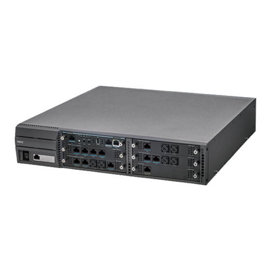
Page 141: Figure 3-1 Chs2Ug-Us Chassis (Front View)
Issue 3.0 Figure 3-1 CHS2UG-US Chassis (Front View) Universal Slot for Legacy Line/Trunk blades and Application blades (six slots). When used as controlling chassis, the GCD-CP10 is mounted in Slot 1 (shown). Slot for GPZ-BS10/GPZ-BS11 blade – Connection with CHS2UG-US chassis Power Switch Figure 3-2 CHS2UG-US Chassis (Rear View) AC Connector... -
Page 142: Installing The 19" Controlling Chassis
Issue 3.0 3.3.1 Installing the 19” Controlling Chassis Ensure the chassis is powered down. Do not remove or install blades with the power on. WARNING Align the GCD-CP10 blade with the Slot 1 guides of the Controlling Chassis. Figure 3-3 19” Controlling Chassis – Guides Slot 1 Slide the GCD-CP10 blade into the chassis until resistance (back plane) is felt. -
Page 143: Installing Expansion Blades In The 19" Chassis (Optional)
The Expansion cable connects the Controlling Chassis and its GPZ-BS10 interface to the second, third, and fourth GPZ-BS11 interface. Use only the CAT 5 cables provided by NEC to make the connections between the Controlling and Expansion Chassis. The GPZ-BS10 provides: Communication Processor Interface for data handling through ... -
Page 144: Connector Pin-Out On The Gpz-Bs10/Gpz-Bs11
Issue 3.0 3.3.2.1 Connector Pin-Out on the GPZ-BS10/GPZ-BS11 Table 3-3 GPZ-BS10/GPZ-BS11 Connector Pin-Out RJ-61 Cable Connector GPZ-BS10 – CN2, CN3, CN 4 GPZ-BS11 – CN3 Pin No. Connection HW_UP (+) HW_UP (-) HW_DWN (+) FS (+) FS (-) HW_DWN (-) CK8M (+) CK8M (-) 3.3.2.2... -
Page 145: Figure 3-7 Gpz-Bs10 Expansion Bay In Controlling Chassis
Issue 3.0 Figure 3-7 GPZ-BS10 Expansion Bay in Controlling Chassis Expansion Bay From the left side of the chassis, pull cover outward to expose the expansion bay. Figure 3-8 Open Base Chassis Cover Pull the cover toward you to remove. Cover must be removed prior to installation of GPZ-BS10 ... -
Page 146: Figure 3-9 Gpz-Bs10 Blade Guides
Issue 3.0 Align the GPZ-BS10 blade with the guides located in the expansion bay. Figure 3-9 GPZ-BS10 Blade Guides Slide the GPZ-BS10 blade into the chassis until resistance (back plane) is felt. Figure 3-10 Installing GPZ-BS10 Blade in Expansion Bay Gently push until the blade seats and install the supplied retaining screw. -
Page 147: Install The Gpz-Bs11 Expansion Blade In The Chs2Ug-Us Expansion Chassis
Issue 3.0 Figure 3-11 GPZ-BS10 Blade Installed Close the GPZ-BS10 cover. Figure 3-12 GPZ-BS10 Installed (Cover Closed) 3.3.2.3 Install the GPZ-BS11 Expansion Blade in the CHS2UG-US Expansion Chassis Figure 3-13 GPZ-BS11 Components For the Expansion Chassis to function, the GPZ-BS10 blade must be installed in Controlling Chassis. -
Page 148: Figure 3-14 Gpz-Bs11 Expansion Bay In Expansion Chassis
Issue 3.0 Do not remove or install this blade with the power WARNING Ensure the chassis is powered down. Locate the door positioned on the left end (expansion bay) of the Expansion Chassis. Figure 3-14 GPZ-BS11 Expansion Bay in Expansion Chassis Expansion Bay From the left side of the chassis, pull cover outward to expose the expansion bay (refer to... -
Page 149: Figure 3-16 Gpz-Bs11 Blade Guides
Issue 3.0 Align the GPZ-BS11 blade with the guides located within the expansion bay. Figure 3-16 GPZ-BS11 Blade Guides Slide the GPZ-BS11 blade into the chassis until resistance (back plane) is felt. Figure 3-17 Installing GPZ-BS11 Blade in Expansion Chassis Gently push until the blade seats and install the supplied retaining screw. -
Page 150: Figure 3-18 Gpz-Bs11 Blade Installed
Issue 3.0 Align the door tabs with hinges and reattach the cover. Figure 3-18 GPZ-BS11 Blade Installed Close the GPZ-BS11 blade cover. Figure 3-19 GPZ-BS11 Installed (Cover Closed) 3-16 Installing the SV9100 Chassis... -
Page 151: Connect The Controlling And Expansion Chassis
Controlling Chassis GPZ-BS10 Ensure Controlling and Expansion chassis are powered down. Using the NEC provided CAT5 straight-through cable(s), attach one end to each Expansion Chassis CN2 connector on the GPZ-BS11 blade (see Figure 3-21 System Expansion Cabling on page 3-18). -
Page 152: Figure 3-21 System Expansion Cabling
Issue 3.0 Figure 3-21 System Expansion Cabling Install in Expansion Chassis Install in Expansion Chassis Install in Expansion Chassis Install in Controlling Chassis Repeat for additional Expansion Chassis. 3-18 Installing the SV9100 Chassis... -
Page 153: Install Grounding On 19" Chassis
Issue 3.0 3.3.3 Install Grounding on 19” Chassis From the factory, the SG, ETH and PBXG grounds are located inside the chassis and are connected to the FG ground (frame ground) on the back of the chassis. Each chassis (CHS2UG-US) in the system must be grounded separately using the procedure listed below. -
Page 154: Install Ac Power Cords On 19" Chassis
Issue 3.0 Figure 3-23 19” Chassis Grounding Lug (Multiple-Chassis) FG Lugs Electrical Service Ground 3.3.5 Install AC Power Cords on 19” Chassis Locate the supplied AC power cord and attach to the AC Inlet located on the back of the Controlling Chassis. Figure 3-24 Install the AC Power Cord CHS2UG-US AC Inlet... -
Page 155: Install Ac Power Cords On Multiple 19" Chassis (Optional)
Issue 3.0 3.3.6 Install AC Power Cords on Multiple 19” Chassis (Optional) To install the AC power cords, locate the supplied AC power cords and attach to the AC Inlets located on the back of the Controlling and Expansion Chassis. Figure 3-25 Install 19”... -
Page 156: Installing The 9.5" Gateway (Chs2Ug Gw-Us) And Base
Issue 3.0 Installing the 9.5” Gateway (CHS2UG GW-US) and Base (CHS2UG B-US) Chassis The CHS2UG GW-US and the CHS2UG B-US chassis have three universal blade slots for station, trunk and optional blades. Before proceeding with installation of chassis, ensure site preparation is completed. -
Page 157: (Chs2Ug B-Us) Chassis
Issue 3.0 Figure 3-27 9.5” Chassis (Rear View) CHS2UG B Chassis For External Battery AC Inlet Ground (12V Connection) 3.4.1 Install Grounding on 9.5” Gateway or Base Chassis Ensure the 9.5” chassis (CHS2UG GW-US or CHS2UG B-US) is powered off and the AC power cord is unplugged. Ground the chassis by connecting a 14 AWG wire from the FG lug on the back side of the chassis to an electrical service ground (such as a cold water pipe). -
Page 158: Installing The 9.5" Base (Chs2Ug B-Us) And Expansion (Chs2Ug E) Chassis
Issue 3.0 Installing the 9.5” Base (CHS2UG B-US) and Expansion (CHS2UG E) Chassis The CHS2UG B-US and CHS2UG E chassis combined have six universal blade slots for legacy line/trunk blade (Single Line Telephone Interface, Digital multiline terminal Interface, Central Office Trunk, ISDN PRI Interface, etc.), In-skin Application Blades (In-skin UMS, In-Skin Router, etc.). -
Page 159: Connecting The 9.5" Base And Expansion Chassis
Issue 3.0 The 9.5" Base chassis provides up to 16 trunk ports or 32 extension ports. An Expansion Chassis can be installed to the right of the Controlling or Base Chassis providing an additional 48 ports (40 trunk/ 80 stations maximum) and can include any combination of stations and trunks below this number. -
Page 160: Figure 3-30 Installing The Expansion Bracket
Issue 3.0 Match the Joint Bracket with screw holes A, B, C and D on the side of the Base Chassis (refer to Figure 3-30 Installing the Expansion Bracket), and install with four M4 x 14 screws. Figure 3-30 Installing the Expansion Bracket From the Expansion Chassis, loosen and remove screws d and e from the top cover (refer to Figure 3-31 Remove Expansion Chassis... -
Page 161: Figure 3-32 Connecting The Base And Expansion Chassis
Issue 3.0 Align the Backboard Connector on the Expansion and Base chassis (refer to Figure 3-32 Connecting the Base and Expansion Chassis), and push the two chassis together. Figure 3-32 Connecting the Base and Expansion Chassis Secure the Base and Expansion chassis using four screws in holes D and E on the top (refer to Figure 3-33 Securing the Expansion Chassis to the Expansion... -
Page 162: Figure 3-35 Installing Reinforcement Bracket
Issue 3.0 Figure 3-34 Install Expansion Chassis Cover Using two screws, secure the Base and Expansion chassis together with the metal reinforcement bracket provided. Be sure to mount the Reinforcement Bracket with the 9.5 inch Base and Expansion Chassis in the vertical position. IMPORTANT The Reinforcement Bracket and two screws are provided with the 9.5 inch Chassis. -
Page 163: Installing Expansion Blades In The 9.5" Base And Expansion
The Expansion cable connects the Controlling Chassis and its GPZ-BS10 interface to the second, third, and fourth GPZ-BS11 interface. Use only the CAT 5 cables provided by NEC to make the connections between the Controlling and Expansion Chassis. The GPZ-BS10 provides: Communication Processor Interface for data handling through ... -
Page 164: Connector Pin-Out On The Gpz-Bs10/Gpz-Bs11
Issue 3.0 3.5.2.1 Connector Pin-Out on the GPZ-BS10/GPZ-BS11 Table 3-4 GPZ-BS10/GPZ-BS11 Connector Pin-Out RJ-61 Cable Connector GPZ-BS10 – CN2, CN3, CN 4 GPZ-BS11 – CN3 Pin No. Connection HW_UP (+) HW_UP (-) HW_DWN (+) FS (+) FS (-) HW_DWN (-) CK8M (+) CK8M (-) 3.5.2.2... -
Page 165: Figure 3-37 Chs2Ug B-Us Expansion Bay
Issue 3.0 Figure 3-37 CHS2UG B-US Expansion Bay Pull the cover toward you to remove. Cover must be removed prior to installation of GPZ-BS10 blade. IMPORTANT Remove knockout in center of cover. Align the GPZ-BS10 blade with the guides located in the expansion bay. -
Page 166: Figure 3-38 Installing The Gpz-Bs10
Issue 3.0 Figure 3-38 Installing the GPZ-BS10 Install the supplied retaining screw (refer to Figure 3-38 Installing the GPZ-BS10). Insert tabs a, b and c into holes A, B and C (refer to Figure 3-39 Completing the Installation) and close the cover. Figure 3-39 Completing the Installation 3-32 Installing the SV9100 Chassis... -
Page 167: Install The Gpz-Bs11 Expansion Blade In The Chs2Ug B-Us Expansion Chassis
Issue 3.0 3.5.2.3 Install the GPZ-BS11 Expansion Blade in the CHS2UG B-US Expansion Chassis Figure 3-40 GPZ-BS11 Components For the Expansion Chassis to function, the GPZ-BS10 blade must be installed in Controlling Chassis. CAUTION Do not remove or install this blade with the power WARNING Ensure the chassis is powered down. -
Page 168: Figure 3-42 Installing The Gpz-Bs11
Issue 3.0 Align the GPZ-BS11 blade with the guides located in the expansion bay. Slide the GPZ-BS11 blade into the chassis until resistance (back plane) is felt. Figure 3-42 Installing the GPZ-BS11 Install the supplied retaining screw. Insert tabs a, b and c into holes A, B and C (refer to Figure 3-43 Completing the Installation) and close the cover. -
Page 169: Connect The Controlling And Expansion Chassis
CAUTION cabling Ensure Controlling and Expansion chassis are powered down. Using the NEC provided CAT5 straight-through cable(s), attach one end to each Expansion Chassis CN2 connector on the GPZ-BS11 blade (see Figure 3-44 System Expansion Cabling). Attach the opposite end to the CN2, CN3 or CN4 connector on the GPZ-BS10 of the Controlling Chassis. -
Page 170: Installing Grounding On 9.5" Base And Expansion Chassis
Issue 3.0 EXAMPLE: 0 CHS2UG-US (19” Chassis) & 4 CHS2UG B-US/CHS2UG E (9.5” Base Chassis/9.5” Expansion Chassis) 1 CHS2UG-US (19” Chassis) & 3 CHS2UG B-US/CHS2UG E (9.5” Base Chassis/9.5” Expansion Chassis) 2 CHS2UG-US (19” Chassis) & 2 CHS2UG B-US/CHS2UG E (9.5”... -
Page 171: Install Grounding On Multiple 9.5" Base And Expansion Chassis
Issue 3.0 3.5.4 Install Grounding on Multiple 9.5” Base and Expansion Chassis From the factory, the SG, ETH and PBXG grounds are located inside the chassis and are connected to the FG ground (frame ground) on the back of the chassis. Each chassis (CHS2UG B-US) in the system must be grounded separately using the procedure listed below. -
Page 172: Wall Mounting The Chassis
❍ chassis will be positioned. This allows secure anchoring of the screws which support the weight of the chassis. Due to chassis weight, NEC recommends only a single ❍ CHS2UG-US chassis per wall mount. Use the template shown in Figure 3-46 Wall Mount Spacing Guide (19”... - Page 173 Issue 3.0 Figure 3-46 Wall Mount Spacing Guide (19” Chassis) Mark and drill the six holes required for a wall installation. Align screw holes in wall mount brackets with drilled holes. Using six screws, secure the two wall mount brackets to the wall. SV9100 System Hardware Manual 3-39...
-
Page 174: Chapter 3 Installing The Sv9100 Chassis
Issue 3.0 Figure 3-47 Install Wall Mount Brackets with Screws 3-40 Installing the SV9100 Chassis... -
Page 175: Figure 3-48 Securing Metal Fittings To Chassis With Screws
Issue 3.0 Using four screws, secure the metal fittings on the Left and Right sides of the 19” chassis. Figure 3-48 Securing Metal Fittings to Chassis with Screws SV9100 System Hardware Manual 3-41... -
Page 176: Figure 3-49 Secure Metal Fitting To Upper Wall Mount Bracket With A Screw
Issue 3.0 Align the metal fitting with the upper wall mount bracket. The lower metal fitting rests against the lower wall mount bracket. Secure the metal fitting and upper wall mount bracket with a single screw. Figure 3-49 Secure Metal Fitting to Upper Wall Mount Bracket with a Screw 3-42 Installing the SV9100 Chassis... -
Page 177: Figure 3-50 Secure Metal Fitting To Lower Wall Mount Bracket With Screws
Issue 3.0 Using two screws, secure the metal fitting to the lower wall mount bracket. Refer to Figure 3-50 Secure Metal Fitting to Lower Wall Mount Bracket with Screws for screw location. Figure 3-50 Secure Metal Fitting to Lower Wall Mount Bracket with Screws Attach the supplied cable support bracket to either end of the lower wall mount bracket with a single screw (refer to Figure 3-51 Attach... -
Page 178: Figure 3-51 Attach Cable Support Bracket To Lower Wall Mount Bracket
Issue 3.0 Figure 3-51 Attach Cable Support Bracket to Lower Wall Mount Bracket 3-44 Installing the SV9100 Chassis... -
Page 179: Figure 3-52 Attachment Locations Of Cable Support Bracket
Issue 3.0 The cable support bracket can be installed any of the four corners of the 19” chassis (refer to Figure 3-52 Attachment Locations of Cable Support Bracket on page 3-45). Figure 3-52 Attachment Locations of Cable Support Bracket Connect the ground wire to all chassis. Refer to 3.3.3 Install Grounding on 19”... -
Page 180: Figure 3-53 Wall Mount Positioning For 9.5" Base/Expansion Chassis
Issue 3.0 Wall Mounting the 9.5” Gateway (CHS2UG GW-US) and Base (CHS2UG B-US) Chassis When wall mounting the chassis, ensure the wall can support the weight of the chassis and (25 lbs per system chassis ---- including blades, cords, power supply, etc.). -
Page 181: Figure 3-54 Wall Mount Spacing Guide (9.5" Chassis)
Issue 3.0 When mounting the Expansion chassis, leave a space of approximately 0.4 in (10mm) between the two for the EXIFU cable. Figure 3-54 Wall Mount Spacing Guide (9.5” Chassis) Use the template shown in Figure 3-54 Wall Mount Spacing Guide (9.5”... -
Page 182: Figure 3-55 Anchor Bolt From Wall (9.5" Chassis)
Issue 3.0 Figure 3-55 Anchor Bolt from Wall (9.5” Chassis) Align the upper bracket holes a and b with the heads of anchor bolts A and B mounted on the wall and slide downward (refer to Figure 3-56 Align Bracket on Wall (9.5” Chassis)). -
Page 183: Figure 3-57 Install Upper Bracket (9.5" Chassis)
Issue 3.0 Align holes E and F on the MV bracket (upper) with holes on the 9.5 inch Basic Chassis (CHS2UG B-US). Install 2 M4 x 14 screws. 2 M4 x 14 screws are provided with the CHS2UG - MOVABLE WALL MOUNT KIT. -
Page 184: Figure 3-58 Optional Small Battery Box (9.5" Chassis)
Issue 3.0 Figure 3-58 Optional Small Battery Box (9.5” Chassis) Align holes G and H on the MV bracket (lower) with holes on the 9.5 inch Basic Chassis (CHS2UG B-US). Install 2 M4 x 14 screws. 2 M4 x 14 screws are provided with the CHS2UG - MOVABLE WALL MOUNT KIT. -
Page 185: Figure 3-60 Install Lower Bracket (9.5" Chassis)
Issue 3.0 Remove the tape preventing the pin washers from falling off the bottom of the wall mounting bracket. Align the pins shown in step 4 above, with the hinges on the upper and lower brackets mounted on the 9.5 inch Base (CHS2UG B-US) chassis. Figure 3-60 Install Lower Bracket (9.5”... -
Page 186: Figure 3-62 Install The Shaft (9.5" Chassis)
Issue 3.0 Attach the shaft from the mounted wall bracket to the lower bracket and secure using the supplied retaining washer. Figure 3-62 Install the Shaft (9.5” Chassis) Using the 2 M3 x 6 spring washer screws supplied, install the stopper between the chassis and the wall mounted bracket. -
Page 187: Figure 3-64 Chassis Installed (9.5" Chassis)
Issue 3.0 Lift the shaft and close the 9.5 inch chassis. To secure the chassis to the wall, tighten the knurled screws located on the upper and lower brackets. Figure 3-64 Chassis Installed (9.5” Chassis) Connect grounding wire to chassis. Refer to Chapter 4 paragraph Installing the 9.5”... -
Page 188: Figure 3-65 Wall Mount Spacing Guide (Base And Expansion Chassis)
Issue 3.0 4.2.1.1 Wall Mounting the 9.5” Base (CHS2UG B-US) and Expansion (CHS2UG E) Chassis Figure 3-65 Wall Mount Spacing Guide (Base and Expansion Chassis) Use the template shown in Figure 3-65 Wall Mount Spacing Guide (Base and Expansion Chassis) for required spacing before drilling. -
Page 189: Figure 3-66 Anchor Bolt From Wall (9.5" Chassis)
Issue 3.0 Figure 3-66 Anchor Bolt from Wall (9.5” Chassis) Remove the M4 x 8 screws from the wall mount bracket. Use the screw holes marked with the number 2 on the upper and lower brackets. Figure 3-67 Remove Support Bracket (Base and Expansion Chassis) SV9100 System Hardware Manual 3-55... -
Page 190: Figure 3-68 Install Support Bracket (Base And Expansion Chassis)
Issue 3.0 Turn the support 90° and install the M4 x 8 screws previously removed. Figure 3-68 Install Support Bracket (Base and Expansion Chassis) Attach the MV bracket (upper and lower) to the 9.5 inch Base and Expansion chassis. Refer to section 4.2.1 Option 1 –... -
Page 191: Figure 3-69 Chassis Installed (Base And Expansion Chassis)
Issue 3.0 Figure 3-69 Chassis Installed (Base and Expansion Chassis) Connect grounding wire to chassis. Refer to Chapter 4 paragraph 3.5 Installing the 9.5” Base (CHS2UG B-US) and Expansion (CHS2UG E) Chassis on page 3-24 for complete details on grounding the system. Refer to 3.5.5 Install AC Power Cord on 9.5”... -
Page 192: Figure 3-70 Wall Mount Spacing Guide (9.5" Chassis)
Issue 3.0 4.2.2 Option 2 – Wall Mounting the 9.5 inch Base CHS2UG B-US Chassis Figure 3-70 Wall Mount Spacing Guide (9.5” Chassis) Use the template shown in Figure 3-54 Wall Mount Spacing Guide (9.5” Chassis) for required spacing before drilling. Plywood should first be installed on the wall where the chassis will be positioned. -
Page 193: Figure 3-71 Anchor Bolt From Wall (9.5" Chassis)
Issue 3.0 Figure 3-71 Anchor Bolt from Wall (9.5” Chassis) 4.2.2.1 Wall Mounting the CHS2UG B-US without the CHS2UG B Small Batt Box Align the bracket halves (refer to Figure 3-72 Wall Mounting Brackets (Option 2)). Figure 3-72 Wall Mounting Brackets (Option 2) SV9100 System Hardware Manual 3-59... -
Page 194: Figure 3-73 Install Upper Bracket (Option 2)
Issue 3.0 Align holes E and F on the MV bracket (upper) with holes on the 9.5 inch Basic Chassis (CHS2UG B-US). Install 2 M4 x 14 screws. M4 x 14 screws are provided with the WALL MOUNT BRACKET. Figure 3-73 Install Upper Bracket (Option 2) Align holes G and H on the MV bracket (lower) with holes on the 9.5 inch Basic Chassis (CHS2UG B-US). -
Page 195: Figure 3-75 Install Screws (Option 2)
Issue 3.0 Align the upper and lower bracket holes with the heads of anchor bolts mounted on the wall and slide downward (refer to Figure 3-75 Install Screws (Option 2)). Figure 3-75 Install Screws (Option 2) Attach the MV bracket (upper and lower) to the 9.5 inch Base and Expansion chassis. -
Page 196: Figure 3-76 Wall Mount Spacing Guide - 9.5" Base And Expansion Chassis
Issue 3.0 Figure 3-76 Wall Mount Spacing Guide – 9.5” Base and Expansion Chassis Connect grounding wire to chassis. Refer to Chapter 4 paragraph Installing the 9.5” Base (CHS2UG B-US) and Expansion (CHS2UG E) Chassis on page 3-24 for complete details on grounding the system. -
Page 197: Figure 3-77 Wall Mounting (Small Batt Box)
Issue 3.0 4.2.2.2 Wall Mounting the CHS2UG B-US with the CHS2UG B Small Batt Box To install the CHS2UG B SMALL BATT BOX refer to section Installing the CHS2UG B SMALL BATT BOX on the 9.5” CHS2UG B Chassis on page 3-104 Align the bracket halves (refer to Figure 3-72 Wall Mounting Brackets (Option... -
Page 198: Figure 3-78 Brackets (Small Batt Box)
Issue 3.0 Figure 3-78 Brackets (Small Batt Box) 3-64 Installing the SV9100 Chassis... -
Page 199: Figure 3-79 Reposition Brackets (Small Batt Box)
Issue 3.0 Align the holes marked as R and F. Figure 3-79 Reposition Brackets (Small Batt Box) SV9100 System Hardware Manual 3-65... -
Page 200: Figure 3-80 Install Screws (Small Batt Box)
Issue 3.0 Install the four screws previously removed. Figure 3-80 Install Screws (Small Batt Box) Align the brackets with the holes on the sides of the 9.5 inch Basic Chassis (CHS2UG B-US). Install 2 M4 x 14 screws. Figure 3-81 Wall Mount – Upper Side (Small Batt Box) 3-66 Installing the SV9100 Chassis... -
Page 201: Figure 3-82 Wall Mount - Lower Side (Small Batt Box)
Issue 3.0 Figure 3-82 Wall Mount – Lower Side (Small Batt Box) Align the upper and lower bracket holes with the heads of anchor bolts mounted on the wall and slide downward. Connect grounding wire to chassis. Refer to Chapter 4 paragraph 3.5 Installing the 9.5”... -
Page 202: Figure 3-83 Floor Mount Spacing Guide
Issue 3.0 ECTION LOOR OUNTING THE HASSIS Floor Mounting the 19” (CHS2UG-US) Chassis The CHS2UG-US controlling and expansion chassis can be mounted on the floor using the CHS BASE UNIT and the CHS2UG JOINT BRACKET KIT. 5.1.1 CHS2UG-US Chassis Installation Use the template shown in Figure 3-83 Floor Mount Spacing Guide for required spacing before drilling holes for 0.39”... -
Page 203: Figure 3-85 Install Rubber Feet (19" Chassis)
Issue 3.0 location. Figure 3-84 Secure CHS BASE UNIT with Anchor Bolts Install the five rubber feet to the bottom of the chassis. Figure 3-85 Install Rubber Feet (19” Chassis) Position the chassis on top of the CHS BASE UNIT. SV9100 System Hardware Manual 3-69... -
Page 204: Figure 3-86 Install Chs2Ug Joint Bracket Kit
Issue 3.0 Secure the chassis to the CHS BASE UNIT using eight screws supplied with the CHS2UG JOINT BRACKET KIT. Figure 3-86 Install CHS2UG JOINT BRACKET KIT Connect the ground wire to all chassis. Refer to 3.3.3 Install Grounding on 19” Chassis on page 3-19 for complete details on grounding the system. -
Page 205: Figure 3-87 Install Rubber Feet For Multiple Chassis
Issue 3.0 5.1.2 Multiple CHS2UG-US Chassis Installation Expansion chassis can be secured to the CHS BASE UNIT and require an additional CHS2UG JOINT BRACKET KIT per chassis. Install the five rubber feet to the bottom of each chassis. Figure 3-87 Install Rubber Feet for Multiple Chassis Using supplied screws in the CHS2UG JOINT BRACKET KIT, attach metal brackets to both ends of the 19”... -
Page 206: Figure 3-89 Assemble Stand Mount With Screws
Issue 3.0 Connect the ground wire to all chassis. Refer to 3.3.3 Install Grounding on 19” Chassis on page 3-19 for complete details on grounding the system. Refer to 3.3.5 Install AC Power Cords on 19” Chassis on page 3-20 continue installation of the chassis or, Chapter 6 paragraph Installation and Safety Precautions on page 4-4 for installation of... -
Page 207: Figure 3-90 Secure Chs2Ug-Us Chassis To Chs2Ug Stand Kit (K) With Screws
Figure 3-91 Secure Stand Mount to Floor with Screws on page 3-74) To prevent possible damage to the 19” chassis due to falling, NEC recommends screws be installed in the stand mount brackets as soon as possible. WARNING SV9100 System Hardware Manual... - Page 208 Issue 3.0 Figure 3-91 Secure Stand Mount to Floor with Screws Connect the ground wire to all chassis. Refer to 3.3.3 Install Grounding on 19” Chassis on page 3-19 for complete details on grounding the system. Refer to 3.3.5 Install AC Power Cords on 19” Chassis on page 3-20 continue installation of the chassis or, Chapter 6 paragraph Installation and Safety Precautions on page 4-4 for installation of...
-
Page 209: Figure 3-92 Attach Rubber Feet To Chs2Ug-Us Chassis
Issue 3.0 6.1.2 Multiple CHS2UG-US Chassis Installation Expansion chassis (maximum of three) can be added to the CHS2UG STAND KIT (K) and require an additional CHS2UG STAND KIT (EXT) per chassis. Install the five rubber feet to the bottom of each chassis. Figure 3-92 Attach Rubber Feet to CHS2UG-US Chassis Each additional chassis requires a CHS2UG STAND KIT (EXT) to be installed (refer to... -
Page 210: Figure 3-93 Install Additional Chs2Ug Stand Kit (Ext)
Issue 3.0 Figure 3-93 Install Additional CHS2UG STAND KIT (EXT) Expansion Plates Metal brackets from the CHS2UG JOINT BRACKET KITs are required to secure the top end of the chassis with screws. See Figure 3-94 Install Additional Brackets from CHS2UG JOINT BRACKET KIT on page 3-77. -
Page 211: Figure 3-94 Install Additional Brackets From Chs2Ug Joint Bracket Kit
Figure 3-94 Install Additional Brackets from CHS2UG JOINT BRACKET KIT). To prevent possible damage to the 19” chassis due to falling, NEC recommends screws be installed in the stand mount brackets as soon as possible. WARNING Connect the ground wire to all chassis. Refer to 3.3.3 Install... -
Page 212: Figure 3-95 Attaching The Base Stand
Issue 3.0 Stand Mounting the 9.5” CHS2UG B Chassis The 9.5” chassis can be stand mounted using the brackets supplied. The following section describes this procedure. This bracket is not for use with a combined Base (CHS2UG B-US) and Expansion (CHS2UG E) chassis. A combined Base and Expansion chassis should only be rack or wall mounted. -
Page 213: Figure 3-96 9.5" Chassis With Base Stand Attached
Issue 3.0 When attaching the stand unit to the 9.5” Base chassis, ensure the shape of the stand unit aligns with the shape of the 9.5” chassis NOTE Figure 3-96 9.5” Chassis with Base Stand Attached Install tab slots D, E, F, G, H and I of either bracket (stand unit brackets can be mounted on the left or right side), on tabs d, e, f, g, h and i of the stand unit. -
Page 214: Figure 3-98 Attaching The Second Stand Unit Bracket
Issue 3.0 Install tab slots J, K, L, M, N and O of the remaining bracket on tabs j, k, l, m, n and o on the opposite side of the stand unit. Figure 3-98 Attaching the Second Stand Unit Bracket Align the support bracket with holes P and Q on the stand unit brackets and secure using the two M3 x 8 screws provided. -
Page 215: Figure 3-100 Stand Mount 9.5" Chassis
Figure 3-100 Stand Mount 9.5” Chassis Secure the 9.5” assembly to a flat surface with the four screws supplied. To prevent possible damage to the 19” chassis due to falling, NEC recommends screws be installed in the stand mount brackets as soon as possible. -
Page 216: Figure 3-101 Chs2Ug-Us Rack Mount Brackets
Issue 3.0 ECTION OUNTING THE HASSIS Rack Mounting the 19” (CHS2UG-US) Chassis A single or multiple chassis can be rack mounted. Controlling and Expansion chassis can be racked mounted by stacking them horizontally. The 19” chassis requires two rack mount brackets per chassis for mounting. Each 19"... -
Page 217: Figure 3-103 Rack Mount 19" Chs2Ug-Us
Issue 3.0 Repeat for additional chassis mounting. Figure 3-102 Rack Mount Bracket Installed 19” CHS2UG-US Carefully slide the chassis into desired location in the rack. Make sure the hooks on the mounting bracket are inserted into the back of the chassis, securing it in place. -
Page 218: Figure 3-104 Attach Rack Mount Brackets To 9.5" Chassis
Issue 3.0 Refer to 3.3.5 Install AC Power Cords on 19” Chassis on page 3-20 continue installation of the chassis or, Chapter 6 paragraph 2.1 Installation and Safety Precautions on page 4-4 for installation of blades. Rack Mounting the 9.5” Base (CHS2UG B-US) and Expansion (CHS2UG E) Chassis To rack mount the combined Base (CHS2UG B-US) and Expansion (CHS2UG E) chassis, the IP5D-RACK MOUNT BAR SET is required. -
Page 219: Figure 3-105 Attach Horizontal Rack Bars
Issue 3.0 Attach the two horizontal rack bars at the correct positions on the rack with the screws provided. The bars are used to secure the chassis vertically in the rack. Figure 3-105 Attach Horizontal Rack Bars Secure the (CHS2UG B-US) and (CHS2UG E) chassis to the horizontal bars using two screws at each point (refer to Figure 3-106 Attach (CHS2UG B-US) and (CHS2UG E) Chassis to Rack on page... -
Page 220: Figure 3-106 Attach (Chs2Ug B-Us) And (Chs2Ug E) Chassis To Rack
Issue 3.0 Figure 3-106 Attach (CHS2UG B-US) and (CHS2UG E) Chassis to Rack Connect grounding wire to chassis. Refer to paragraph 3.5.4 Install Grounding on Multiple 9.5” Base and Expansion Chassis on page 3-37 complete details on grounding the system. Refer to 3.5.5 Install AC Power Cord on 9.5”... -
Page 221: Figure 3-107 Removing Battery Access Panel
Issue 3.0 ECTION ATTERY ONNECTION Two types of battery connection provide battery life during a power failure, the internal battery and an external battery with CHSG LARGE BATT BOX. Installing the Internal Batteries 19” (CHS2UG-US) Chassis An internal battery source using two batteries can be installed using the CHS2UG BATT MTG KIT (mounting kit) and CHS2U BATT CABLE INT (internal cabling). -
Page 222: Figure 3-108 Removing Access Panel
Issue 3.0 Remove access panel containing the fan. Refer to Figure 3-108 Removing Access Panel Figure 3-109 Access Panel Removed. Figure 3-108 Removing Access Panel Figure 3-109 Access Panel Removed 3-88 Installing the SV9100 Chassis... -
Page 223: Figure 3-110 Secure Cable In Support Bracket
Issue 3.0 Using tie wraps, secure CHS2U BATT CABLE INT in cable guide bracket. Figure 3-110 Secure Cable in Support Bracket With supplied screw, install cable guide in chassis. Figure 3-111 Installing Cable Support Guide Install two 2.3 AH-12V batteries (locally procured) into the CHS2UG BATT MTG KIT (refer to Figure 3-112 Installing Two Batteries on page 3-90). -
Page 224: Figure 3-112 Installing Two Batteries
Issue 3.0 Figure 3-112 Installing Two Batteries Using the supplied screws, secure the brackets to the CHS2UG BATT MTG KIT (refer to Figure 3-112 Installing Two Batteries). Connect the provided battery cables to the batteries. Figure 3-113 Installing Battery Cable 3-90 Installing the SV9100 Chassis... -
Page 225: Figure 3-114 Connecting Chs2U Batt Cable Int
Issue 3.0 Connect CHS2U BATT CABLE INT to battery connector. Figure 3-114 Connecting CHS2U BATT CABLE INT Install CHS2UG BATT MTG KIT into CHS2UG-US chassis and tighten the retaining screws. Figure 3-115 Installing Battery Tray into CHS2UG-US Chassis SV9100 System Hardware Manual 3-91... -
Page 226: Figure 3-116 Installing The Access Panel
Issue 3.0 Reinstall access panel containing the fan and secure with supplied screw. Figure 3-116 Installing the Access Panel Connect grounding and AC power cable. Installing the External Batteries 19” (CHS2UG-US) Chassis An optional (locally procured), external battery source can be used to provide power during a power failure. -
Page 227: Figure 3-117 Floor Mount Spacing Guide
Issue 3.0 8.2.1 Floor Mounting the CHSG LARGE BATT BOX Because of injury from falling equipment, wall mounting ❍ the CHSG LARGE BATT BOX is not recommended. WARNING Mounting the CHSG LARGE BATT BOX directly on the ❍ floor is not recommended. The CHS BASE UNIT raises the height of the CHSG ❍... -
Page 228: Figure 3-118 Installing The Chsg Large Batt Box Using The Chs2Ug Joint
Issue 3.0 Align bolt holes in CHS BASE UNIT (see Figure 3-117 Floor Mount Spacing Guide on page 3-93) with holes drilled in floor and secure using four anchor bolts. Align and install the CHSG LARGE BATT BOX on top of the CHS BASE UNIT. -
Page 229: Figure 3-120 Removing Battery Tray Suppressor
Issue 3.0 Remove two screws from front of Battery Tray Suppressor. Figure 3-120 Removing Battery Tray Suppressor Slide Battery Tray Suppressor outward to remove. Slide Battery Tray(s) out of CHSG LARGE BATT BOX. Loosen two screws and remove the Battery Tray Cover. Figure 3-121 Removing Battery Tray Cover SV9100 System Hardware Manual 3-95... -
Page 230: Figure 3-123 Battery Cable Connection Guide
Issue 3.0 Remove two screws and remove the Battery Tray Bracket. Figure 3-122 Removing Battery Tray Bracket Refer to Figure 3-123 Battery Cable Connection Guide for connection of battery cable to battery terminals. Repeat for additional battery connection. Incorrect Installation Of Batteries May Damage The Fuse Unit Or Cause Possible Fire. -
Page 231: Figure 3-122 Removing Battery Tray Bracket
Issue 3.0 Using two screws, install the Battery Tray Bracket. Refer to Figure 3-122 Removing Battery Tray Bracket on page 3-96. Figure 3-124 Installing Battery Connection Cable Insert Battery Connection Cable into cable guides. Refer to Figure 3-124 Installing Battery Connection Cable. -
Page 232: Figure 3-126 Installing Cover Battery
Issue 3.0 Figure 3-125 Connecting Battery Cables Insert tabs on cover into holes on CHSG LARGE BATT BOX. Slide the cover left until seated and tighten the screw. Figure 3-126 Installing Cover Battery 8.2.3 CHSG LARGE BATT BOX to CHS2UG-US Connection Power down the CHS2UG-US chassis. -
Page 233: Figure 3-127 Removing Fan Access Panel
Issue 3.0 Remove fan access panel from rear of CHS2UG-US chassis. Figure 3-127 Removing Fan Access Panel Connect one end of Battery Connection Cable to Battery Connector on rear of Basic and Expansion chassis. Figure 3-128 Connecting External Battery to CHS2UG-US Connect other end of cable to Battery Connector on rear of CHSG LARGE BATT BOX chassis. -
Page 234: Figure 3-129 Single Chsg Large Batt Box Connection
Issue 3.0 Figure 3-129 Single CHSG LARGE BATT BOX Connection Basic Expansion Figure 3-130 Dual CHSG LARGE BATT BOX Connection Basic Expansion 3-100 Installing the SV9100 Chassis... -
Page 235: Figure 3-131 Install The Fan Access Panel
Issue 3.0 Insert the access panel tab into the rear of the CHS2UG-US chassis running the Battery Connection Cable through the cutout. Secure panel with the retaining screw. Figure 3-131 Install the Fan Access Panel Connect grounding and AC power cables. Apply power to chassis (refer to Chapter 4, 2.6 Powering Up the SV9100 System on page... -
Page 236: Figure 3-133 Removing Battery Tray Suppressor
Issue 3.0 Remove two screws from front of Battery Tray Suppressor (Refer to Figure 3-133 Removing Battery Tray Suppressor). Figure 3-133 Removing Battery Tray Suppressor Slide Battery Tray Suppressor outward to remove. Disconnect the Battery Connection Cables from the Fuse Unit. Figure 3-134 Disconnecting Battery Cables Loosen two screws and pull Fuse Unit out of the CHSG LARGE BATT BOX. -
Page 237: Figure 3-136 Connecting Battery Cables
Issue 3.0 Figure 3-135 CHSG LARGE BATT BOX Fuse Unit Slide the Fuse Unit into the and tighten the two screws (refer to Figure 3-134 Disconnecting Battery Cables on page 3-102). Plug the Battery Connection Cables into the Fuse Unit. Figure 3-136 Connecting Battery Cables SV9100 System Hardware Manual 3-103... -
Page 238: Figure 3-137 Installing Cover Battery
Issue 3.0 Insert tabs on cover into holes on CHSG LARGE BATT BOX. Slide the cover left until seated and tighten the screw. Figure 3-137 Installing Cover Battery Installing the CHS2UG B SMALL BATT BOX on the 9.5” CHS2UG B Chassis An optional, CHS2UG B SMALL BATT BOX can be installed to provide external battery power to the CHS2UG GW-US and CHS2UG B-US chassis during a... -
Page 239: Figure 3-138 Installing Battery Cable Assembly
Issue 3.0 Figure 3-138 Installing Battery Cable Assembly Remove the battery connector cap on the Base chassis and connect the battery connection cable. Figure 3-139 Installing Battery Connection Cable SV9100 System Hardware Manual 3-105... -
Page 240: Figure 3-140 Removing Battery Cover
Issue 3.0 Remove the two M3 x 8 screws from the Small Battery Box, then remove the battery cover (refer to Figure 3-140 Removing Battery Cover). Figure 3-140 Removing Battery Cover Place the two batteries into the Small Battery Box (refer to Figure 3-141 Installing Batteries on page 3-107). -
Page 241: Figure 3-141 Installing Batteries
Issue 3.0 Figure 3-141 Installing Batteries Route battery cables a and b under the Small Battery Box tabs and connect to connectors A and B. Figure 3-142 Connecting Battery Cables Insert tabs c and d of the battery cover into slots C and D of the Small Battery Box. -
Page 242: Figure 3-144 Unlocking The Small Battery Box
Issue 3.0 Figure 3-143 Installing Battery Cover Pull the battery lock of the Small Battery Box forward to unlock it. Figure 3-144 Unlocking the Small Battery Box 3-108 Installing the SV9100 Chassis... -
Page 243: Figure 3-145 Installing Small Battery Box
Issue 3.0 Align the Small Battery Box with the grooves at the top and bottom of the Base chassis and slide into position. Figure 3-145 Installing Small Battery Box Push the battery lock in, then connect the battery cable. Figure 3-146 Locking the Small Battery Box SV9100 System Hardware Manual 3-109... -
Page 244: Figure 3-147 Disconnecting The Battery Cables
Issue 3.0 Connect grounding wire to chassis. Refer to Chapter 4 paragraph Installing the 9.5” Base (CHS2UG B-US) and Expansion (CHS2UG E) Chassis on page 3-24 for complete details on grounding the system Refer to 3.5.5 Install AC Power Cord on 9.5” Base and Expansion Chassis on page 3-37 for installation of the power cord or, Chapter 6 paragraph... -
Page 245: Figure 3-148 Removing The Fuse
WARNING ❍ not recommended. Due to possible water damage, floor mounting the 9.5” chassis is ❍ not recommended by NEC. The CHS BASE UNIT raises the height of the CHSG LARGE BATT BOX 120mm (4.72”). NOTE 8.4.1 CHSG LARGE BATT BOX Installation... -
Page 246: Figure 3-149 9.5" Chassis (Rear View)
Issue 3.0 8.4.2 CHSG LARGE BATT BOX to 9.5” Gateway (CHS2UG GW-US) or Base (CHS2UG B-US) Chassis Connection Power down the CHS2UG GW-US or CHS2UG B-US chassis. Ensure the CHS2UG GW-US or CHS2UG B-US chassis is powered OFF. WARNING Disconnect AC power cable from rear of chassis. From the back of the 9.5”... -
Page 247: Figure 3-150 Chsg Large Batt Box To Chs2Ug Gw-Us Or
3-101. ECTION OWER UPPLY Do not attempt to replace the power supply on the CHS2UG-US or CHS2UG GW-US chassis. The MPS7101 is not a field replaceable part. If the power supply fails, contact NEC. WARNING SV9100 System Hardware Manual 3-113... - Page 248 Follow the procedure below for the CHS2UG-US chassis. 10.1 CHS2UG-US Chassis 10.1.1 Remove Cooling Fan To reduce the possibility of electrical shock or damage to equipment, NEC recommends powering off the chassis and WARNING disconnecting the AC cable from the power source before removing the chassis cover.
-
Page 249: Figure 3-151 19" Chassis Access Panel
Issue 3.0 Remove chassis access panel from rear of chassis. Remove cabling from retention clips. Figure 3-153 Chassis Access Panel Removed (19” Chassis) Remove two screws securing fan to access cover. Keep screws for use when installing replacement fan [refer to Figure 3-153 Chassis Access Panel Removed (19”... - Page 250 Issue 3.0 3-116 Installing the SV9100 Chassis...
- Page 251 ENERAL NFORMATION This chapter contains information to help the technician install the blades for the UNIVERGE SV9100 system. The technician should be familiar with this section before installing any equipment. Slot Locations Each CHS2UG-US has six slots. In the Controlling Chassis, the GCD-CP10 (for Key Systems) must be installed in the first slot (slot 1).
-
Page 252: Figure 4-1 19" Chassis Cpu And Expansion Slot Locations
Issue 3.0 Figure 4-1 19” Chassis CPU and Expansion Slot Locations Controlling Chassis CPU Slot Expansion Chassis GPZ-BS11 Slot Figure 4-2 9.5” Gateway Chassis CPU Location Installing the SV9100 Blades... -
Page 253: Figure 4-3 9.5" Base And Expansion Chassis Cpu Location
Issue 3.0 Figure 4-3 9.5” Base and Expansion Chassis CPU Location Base Chassis CHS2UG B-US Base Chassis CHS2UG B-US GPZ-BS10 or GPZ-BS11 Slot Expansion Chassis CHS2UG E SV9100 System Hardware Manual... - Page 254 Issue 3.0 ECTION NSTALLATION Pre-installation planning is essential. Advanced planning minimizes installation time, cost, and disruption of the customer business activities. Installation and Safety Precautions Observe the following precautions when installing the blades to avoid static electricity damage to hardware or exposure to hazardous voltages.
-
Page 255: Figure 4-4 Inserting Blades In The 19" Chassis
Issue 3.0 Installing an Extension or Trunk Blade 2.2.1 Installing the Blades To install an extension/trunk blade with the system running: Insert the blade in the guide rail and push it securely into position. Tighten the thumb screw on either side of the blade. The Status LED starts flashing when the blade starts processing (15 seconds). -
Page 256: Table 4-1 Extension Blade Installation Order Example
Issue 3.0 2.2.2 Order of Installing Extension Blades The order in which the station blades (GCD-8DLCA with GPZ-8DLCB, GCD-16DLCA, GCD-4LCA, and GCD-8LCA with GPZ-8LCE) are physically inserted determines the numbering plan. To avoid unexpected extension/trunk numbering if the VoIP or Voice Mail daughter board registers with the system first, install these boards after the other extension and trunk blades are CAUTION... -
Page 257: Table 4-2 Adding Daughter Board To Chassis Example
Issue 3.0 Table 4-2 Adding Daughter Board to Chassis Example Blade Extension Blade Extension Blade Blade Slot # Numbers Slot # Numbers GCD-16DLCA 101~116 GCD-16DLCA 101~116 GCD-8DLCA 117~124 (no daughter — — board) GCD-16DLCA 125~140 GCD-16DLCA 125~140 GCD-8DLCA 141~156 (with daughter —... -
Page 258: Table 4-3 Trunk Blade Installation Order Example
Issue 3.0 For example, if four blades are installed in the following order, the numbering plan below applies. Table 4-3 Trunk Blade Installation Order Example Order of Blade Slot Blade Line Circuits Installation Number GCD-4COTB with GPZ-4COTF GCD-4COTB 9~12 13~16 GCD-4ODTA 17~20 GCD-4ODTA... - Page 259 Controlling and Expansion Chassis in programming for port renumbering or to replace it with a different blade. Deleting a blade may affect blade slot programming ability. Refer to Program 90-05 in the UNIVERGE SV9100 Programming Manual for detailed information.
- Page 260 Issue 3.0 2.6.2 Performing a Hot Start The section describes how to load system software from flash memory and customer data from RAM memory. IMPORTANT CONSIDERATIONS System software is loaded from flash memory, and customer CAUTION data is from RAM memory. Turn the system power off.
-
Page 261: Table 4-4 Default Port Settings
Issue 3.0 2.6.3.2 Port Defaults With the default settings, the ports are assigned as follows: Table 4-4 Default Port Settings Port 1~99 : 101~199 Station Ports: Port 100~199 : 3101~3200 Port 200~960 : 3201~3961 Port 1~99 : 201~299 Virtual Station Port 100~512 : No Setting Ports: 1~400... - Page 262 Issue 3.0 2.6.3.5 Backing Up/Restoring a Database As a precaution, it is recommended that the customer database be saved prior to updating the system software. There are two methods to save the database – either use the PCPro application or save directly to USB Memory on GCD-CP10. Using PCPro, download the database and save the file on the PC hard drive.
- Page 263 Issue 3.0 2.6.4 Performing a Software Upgrade This section describes the procedure to perform a software upgrade on the GCD-CP10. IMPORTANT CONSIDERATIONS To save customer data prior to updating, a blank USB Memory is ❍ CAUTION required. Insert the USB Memory into the USB Port on the GCD-CP10 blade.
- Page 264 Issue 3.0 Turn the system power back on. When the system has completed reloading the software, the Status LED begins flashing on the GCD-CP10. The remaining four LEDs are off. To confirm the new software version is installed, press the ...
-
Page 265: Figure 4-6 Gcd-Cp10 Blade Layout
Issue 3.0 ECTION OMMON ONTROL LADES The blades described in this section control the common functions of the chassis. GCD-CP10 (SV9100 Central Processing Unit) Figure 4-6 GCD-CP10 Blade Layout SV9100 System Hardware Manual 4-15... -
Page 266: Figure 4-7 Gcd-Cp10 Blade With Daughter Boards Installed
Issue 3.0 Figure 4-7 GCD-CP10 Blade with Daughter Boards Installed 3.1.1 Description The GCD-CP10 controls all the functions and operations of the SV9100 system using the system software loaded into the GCD-CP10 memory. The system software can be upgraded as new software becomes available. One GCD-CP10 blade must be installed in the Controlling Chassis. - Page 267 Issue 3.0 GPZ-BS10/GPZ-BS11 Interface Circuit Main Processing 32-Bit CPU Circuit (P1015 @ 533 MHz) Time Switch, Optional Blade Control Circuit Backboard Interface Circuit The GCD-CP10 provides: 400 trunk ports maximum 896 extension ports maximum 896 ports digital/IP extensions maximum ...
- Page 268 A load switch which is used for initial system startup, resetting the system, or when upgrading system software One Serial Port (NEC production use only) One SD/SDHC Card (VM) connector One USB Port – USB 1.1/USB 2.0 ...
-
Page 269: Figure 4-8 Gcd-Cp10 Battery Installation
Issue 3.0 3.1.2 Installation Each SV9100 system must have the GCD-CP10 installed in Slot 1 of the Controlling Chassis. IMPORTANT CONSIDERATIONS The chassis power must be off when installing or removing ❍ CAUTION the GCD-CP10. After removing a previously installed GCD-CP10, handle ❍... -
Page 270: Table 4-5 Sram Data Types
Issue 3.0 Push down on the battery, opposite from the plus (+) symbol (refer to Figure 4-8 GCD-CP10 Battery Installation). Battery Removal Before removing the GCD-CP10 from the ❍ chassis to install or replace a battery, ensure the system is powered Off. CAUTION When removing the backup battery, SRAM ❍... - Page 271 Issue 3.0 Load the SRAM data saved in step 1, above. From the PCPro “System Data Save/Load/Verify” menu load the data from the specified file. - OAI FLF Memory Battery replacement is complete. 3.1.2.2 GPZ-IPLE Daughter Board Installation Refer to Figure 4-10 Installing the GPZ-IPLE Daughter Board on page 4-28 to install the GPZ-IPLE daughter board,...
-
Page 272: Table 4-6 Gcd-Cp10 Switch Settings
Issue 3.0 3.1.3 Switch Settings Refer to Table 4-6 GCD-CP10 Switch Settings for system restart/system reset and with system power on. Figure 4-6 GCD-CP10 Blade Layout on page 4-15 shows the location of the LOAD (S5) switch on the GCD-CP10 blade. -
Page 273: Table 4-8 Gcd-Cp10 Led Indications
Issue 3.0 3.1.4 LED Indications The LEDs on the GCD-CP10 indicate the following: RUN (D23) = The CPU is operating (green) D20, and D21 = Alarms (red) D22 = SD Memory Card access/Alarm indication (red) D25 = The USB memory connection status (red) ... -
Page 274: Table 4-9 Gcd-Cp10 Connections
Issue 3.0 Table 4-8 GCD-CP10 LED Indications (Continued) LED Indication Status RUN (D23) Blinking On Steady When SRAM error USB Memory is Installing Blinking On Steady When SD memory booting error USB Memory is Installing Blinking On Steady When SD memory data error USB Memory is Installing Blinking... - Page 275 Issue 3.0 Table 4-9 GCD-CP10 Connections (Continued) Connector Connector Description SD Memory Card Connection Backboard Connection GPZ-IPLE Connection Lithium Battery Socket - for backup of SRAM data and RTC (Real Time Clock) data LOAD (S5) Load Switch SENSE Switch Table 4-10 GCD-CP10 RJ45 Cable Connector Pin-Outs USB Cable Connector –...
- Page 276 Issue 3.0 Table 4-10 GCD-CP10 RJ45 Cable Connector Pin-Outs (Continued) Pin Jack – J11/J12 (Polarity) Pin No. Signal EXT1 EXT2 RJ-45 Cable Connector – J10 (External Source Control) (No Polarity) Pin No. Connection EXCNT2 EXCNT1 EXCNT1 EXCNT2 4-26 Installing the SV9100 Blades...
-
Page 277: Figure 4-9 Iple Daughter Board
Issue 3.0 GPZ-IPLE (Voice over IP Daughter Board) Figure 4-9 IPLE Daughter Board 3.2.1 Description The current GPZ-IPLE daughter board requires a single DSP IP address. With SV9100 software and GPZ-IPLE daughter board ❍ installed, half-duplex connections are not supported. CAUTION For troubleshooting purposes, a managed switch capable of ❍... -
Page 278: Figure 4-10 Installing The Gpz-Iple Daughter Board
3-8 for more details. Connect the IPLE daughter board to the CD-RTB or to an external switching hub using an Ethernet cable. Refer to the UNIVERGE SV9100 Programming Manual for detailed programming instructions. 3.2.3 Switch Settings This daughter board does not have any switch that needs to be set and does not require any hardware setting. -
Page 279: Table 4-11 Iple Daughter Board Led Indications
Issue 3.0 3.2.4 LED Indications LED indications for the GPZ-IPLE Daughter Board are indicated in Table 4-11 IPLE Daughter Board LED Indications on page 4-29. Each LED is listed with its associated function and LED and Operational status. Refer to Figure 4-7 GCD-CP10 Blade with Daughter Boards Installed on page 4-16 for the location of the LEDs on the blades. -
Page 280: Figure 4-11 Iple Led Interface
Issue 3.0 Refer to Figure 4-11 IPLE LED Interface for a functional display of the LED interface when installed on a GCD-CP10. Figure 4-11 IPLE LED Interface 3.2.5 Connectors Figure 4-12 VoIP Connections on page 4-31 shows a typical connection layout. - Page 281 Issue 3.0 Figure 4-12 VoIP Connections SV9100 System Hardware Manual 4-31...
- Page 282 Issue 3.0 Figure 4-13 Connecting an IPLE Daughter Board to a Network/PC 4-32 Installing the SV9100 Blades...
-
Page 283: Figure 4-14 Gcd-8Dlca/Gcd-16Dlca Blade
Issue 3.0 ECTION TATION LADES GCD-8DLCA/GCD-16DLCA (Digital Station Interface) Figure 4-14 GCD-8DLCA/GCD-16DLCA Blade SV9100 System Hardware Manual 4-33... - Page 284 Issue 3.0 4.1.1 Description The GCD-8DLCA and the GCD-16DLCA are both discussed in this section. Any differences between the two are noted. These blades provide: 8 (GCD-8DLCA) OR 16 (GCD-16DLCA) digital extension circuits (used for digital telephones, DSS consoles, SLT(1)-U( ) ADP, PGD(2)-U10 ADP adapters) These ports provide -48V feeding.
-
Page 285: Table 4-13 Gcd-8Dlca/Gcd-16Dlca Led Indications
Issue 3.0 Table 4-13 GCD-8DLCA/GCD-16DLCA LED Indications LED Indication Operation Status Remarks Live LED Busy LED (Green) (Red) System Initializing – When you exceed the system capacity. Flash (1s) The assignment of the unit is refused. When the main software version is not matched. - Page 286 Issue 3.0 Table 4-14 GCD-8DLCA/GCD-16DLCA/ RJ-61 Cable Connector Pin-Outs RJ-61 Cable Connector GCD-8DLCA – CN101 (ports 1~4), CN201 (ports 5~8) GCD-16DLCA – CN101 (ports 1~4), CN201 (ports 5~8), CN301 (ports 9~12), CN401 (ports 13~16) Pin No. Connection T4 (Tip for port 4) T3 (Tip for port 3) T2 (Tip for port 2) R1 (Ring for port 1)
- Page 287 Issue 3.0 GPZ-8DLCB (Digital Station Daughter Board) Figure 4-15 GPZ-8DLCB Daughter Board 4.2.1 Description The GPZ-8DLCB daughter board provides eight digital extensions. This daughter board is installed on the GCD-8DLCA and expands the port capacity for the combined blades to 16. SV9100 System Hardware Manual 4-37...
-
Page 288: Figure 4-15 Gpz-8Dlcb Daughter Board
Issue 3.0 Refer to the following tables for maximum upgrade capacities of the GPZ-8DLCB daughter board: Table 2-6 SV9100 Maximum 9.5” Gateway and 19” System Capacities – Blades on page 2-12 Table 2-7 SV9100 Maximum 9.5” Base and Expansion System ... - Page 289 Issue 3.0 Table 4-15 GPZ-8DLCB RJ-61 Cable Connector Pin-Outs (Continued) RJ-61 Cable Connector CN401 (ports 13~16) Pin No. Connection (T4) Tip for port 16 (T3) Tip for port 15 (T2) Tip for port 14 (R1) Ring for port 13 (T1) Tip for port 13 (R2) Ring for port 14 (R3) Ring for port 15 (R4) Ring for port 16...
-
Page 290: Figure 4-16 Gcd-4Lca/Gcd-8Lca Blade
Issue 3.0 GCD-4LCA/GCD-8LCA (4-Port/8-Port Single Line Interface) Figure 4-16 GCD-4LCA/GCD-8LCA Blade 4.3.1 Description The GCD-4LCA/GCD-8LCA blade provides four analog (SLIU) extension ports or eight analog (SLIU) extension ports (used for on-premise analog telephones, fax machines, and analog modems). 4-40 Installing the SV9100 Blades... - Page 291 Issue 3.0 The GCD-4LCA and GCD-8LCA are not rated for OPX use. A GCD-4DIOPA blade should be used instead (it supports the analog DID and single line telephone interface functions, such as Off-Premise Extensions). One extension status LED One blade status LEDs ...
-
Page 292: Table 4-16 Gcd-4Lca/Gcd-8Lca Led Indications
Issue 3.0 4.3.3 LED Indications LED indications for the GCD-4LCA GCD-8LCA are listed in Table 4-16 GCD-4LCA/GCD-8LCA LED Indications. Each LED is listed with its associated function and LED and Operational status. Refer to Figure 4-16 GCD-4LCA/GCD-8LCA Blade on page 4-40 for the location of the LEDs on the blades. - Page 293 Issue 3.0 Table 4-17 GCD-4LCA/GCD-8LCA RJ-61 Cable Connector Pin-Outs RJ-61 Cable Connector GCD-4LCA – CN2 (ports 1~4) GCD-8LCA – CN2 (ports 1~4) CN3 (ports 5~8) Pin No. Connection T4 (Tip for port 4) T3 (Tip for port 3) T2 (Tip for port 2) R1 (Ring for port 1) T1 (Tip for port 1) R2 (Ring for port 2...
-
Page 294: Figure 4-17 Installing The Gpz-4Lca/Gpz-8Lce Daughter Board
Issue 3.0 GPZ-4LCA/GPZ-8LCE (4-Port/8-Port SLI Daughter Board) Figure 4-17 Installing the GPZ-4LCA/GPZ-8LCE Daughter Board 4.4.1 Description The GPZ-4LCA and GPZ-8LCE daughter boards are mounted on the GCD-4LCA/GCD-8LCA. These boards provide: 4-Port Single Line and 8-Port Single Line analog extension ports ... -
Page 295: Table 4-18 Gpz-4Lca/Gpz-8Lce/ Rj-61 Cable Connector Pin-Outs
Issue 3.0 Each CN2 (GPZ-4LCA GPZ-8LCE) or CN3 (GPZ-8LCE only) connector provides connection to four analog station ports and is not polarity sensitive. The GPZ-8LCE consumes eight ports ranging between ports 001~256 (remember that the GCD-8LCA consumes eight ports). Refer to the following tables for maximum upgrade capacity of the GPZ-4LCA/GPZ-8LCE SLI daughter board: Table 2-6 SV9100 Maximum 9.5”... - Page 296 Issue 3.0 Table 4-18 GPZ-4LCA/GPZ-8LCE/ RJ-61 Cable Connector Pin-Outs RJ-61 Cable Connector – GPZ-4LCA – CN2 (ports 9~12) GPZ-8LCE – CN2 (ports 9~12) CN3 (ports 13~16) Pin No. Connection T4 (Tip for port 4) T3 (Tip for port 3) T2 (Tip for port 2) R1 (Ring for port 1) T1 (Tip for port 1) R2 (Ring for port 2)
-
Page 297: Figure 4-18 Gcd-4Lcf/Gcd-8Lcf Blade
Issue 3.0 GCD-4LCF/GCD-8LCF (4-Port/8-Port Single Line Interface) Figure 4-18 GCD-4LCF/GCD-8LCF Blade 4.5.1 Description The GCD-4LCF/GCD-8LCF blade provides four analog (SLIU) extension ports or eight analog (SLIU) extension ports (used for on-premise analog telephones, fax machines, and analog modems). SV9100 System Hardware Manual 4-47... - Page 298 Issue 3.0 The GCD-4LCF and GCD-8LCF are not rated for OPX use. A GCD-4DIOPA blade should be used instead (it supports the analog DID and single line telephone interface functions, such as Off-Premise Extensions). One extension status LED One blade status LEDs ...
-
Page 299: Table 4-19 Gcd-4Lcf/Gcd-8Lcf Led Indications
Issue 3.0 4.5.3 LED Indications LED indications for the GCD-4LCF GCD-8LCF are listed in Table 4-19 GCD-4LCF/GCD-8LCF LED Indications. Each LED is listed with its associated function and LED and Operational status. Refer to Figure 4-18 GCD-4LCF/GCD-8LCF Blade on page 4-47 for the location of the LEDs on the blades. - Page 300 Issue 3.0 Table 4-20 GCD-4LCF/GCD-8LCF RJ-61 Cable Connector Pin-Outs RJ-61 Cable Connector GCD-4LCF – J3 (ports 1~4) GCD-8LCF – J3 (ports 1~4), J4 (ports 5~8) Pin No. Connection T4 (Tip for port 4) T3 (Tip for port 3) T2 (Tip for port 2) R1 (Ring for port 1) T1 (Tip for port 1) R2 (Ring for port 2...
-
Page 301: Figure 4-19 Installing The Gpz-4Lcf/Gpz-8Lcf Daughter Board
Issue 3.0 GPZ-4LCF/GPZ-8LCF (4-Port/8-Port SLI Daughter Board) Figure 4-19 Installing the GPZ-4LCF/GPZ-8LCF Daughter Board 4.6.1 Description The GPZ-4LCF and GPZ-8LCF daughter boards are mounted on the GCD-4LCF/GCD-8LCF. These boards provide: 4-Port Single Line and 8-Port Single Line analog extension ports ... -
Page 302: Table 4-21 Gpz-4Lcf/Gpz-8Lcf/ Rj-61 Cable Connector Pin-Outs
Issue 3.0 Each J3 (GPZ-4LCF GPZ-8LCF) or J4 (GPZ-8LCF only) connector provides connection to four analog station ports and is not polarity sensitive. The GPZ-8LCF consumes eight ports ranging between ports 1~1536 (remember that the GCD-8LCF consumes eight ports). Refer to the following tables for maximum upgrade capacity of the GPZ-4LCF/GPZ-8LCF SLI daughter board: Table 2-6 SV9100 Maximum 9.5”... - Page 303 Issue 3.0 Table 4-21 GPZ-4LCF/GPZ-8LCF/ RJ-61 Cable Connector Pin-Outs RJ-61 Cable Connector – GPZ-4LCF – J3 (ports 9~12) GPZ-8LCF – J3 (ports 9~12), J4 (ports 13~16) Pin No. Connection T4 (Tip for port 4) T3 (Tip for port 3) T2 (Tip for port 2) R1 (Ring for port 1) T1 (Tip for port 1) R2 (Ring for port 2)
-
Page 304: Figure 4-20 Gcd-Lta Blade
Issue 3.0 term GCD-LTA (D /SLT Combination) Figure 4-20 GCD-LTA Blade 4.7.1 Description The Digital Station/SLT Combination blade provides eight Digital Station ports and two analog ports. This blade allows either a GPZ-4COTF analog trunk daughter board or GPZ-2BRIA daughter board to be installed. 4-54 Installing the SV9100 Blades... - Page 305 Issue 3.0 The blade provides: Eight Digital Station ports Two analog extension ports support Caller ID Circuit, Message Waiting Lamp Control (Controlling Voltage:-110Vdc) for all ports Two status LEDs Refer to the following tables for maximum upgrade capacities of the GCD-LTA blade: Table 2-6 SV9100 Maximum 9.5”...
-
Page 306: Table 4-22 Gcd-Lta Led Indications
Issue 3.0 4.7.3 LED Indications LED indications for the GCD-LTA are indicated in Table 4-22 GCD-LTA LED Indications. Each LED is listed with its associated function and LED and Operational status. Refer to Figure 4-20 GCD-LTA Blade on page 4-54 the location of the LEDs on the blade. -
Page 307: Table 4-23 Gcd-Lta Rj11 Cable Connector Pin-Outs
Issue 3.0 4.7.4 Connectors Table 4-23 GCD-LTA RJ11 Cable Connector Pin-Outs shows the pin-outs for the RJ-61 connector. Refer to Figure 4-20 GCD-LTA Blade on page 4-54 for an illustration showing the location of the connectors on the GCD-LTA blade. Table 4-23 GCD-LTA RJ11 Cable Connector Pin-Outs RJ11 Cable Connector DLCA: CN101 (ports 1~4) -
Page 308: Figure 4-21 Gcd-4Cotb Blade
Issue 3.0 ECTION RUNK LADES GCD-4COTB (4 Loop and Ground Start Interface) Figure 4-21 GCD-4COTB Blade 4-58 Installing the SV9100 Blades... - Page 309 Issue 3.0 5.1.1 Description The GCD-4COTB blade provides: GCD-4COTB: Four analog loop start/ground start trunk circuits One trunk status LED One Blade status LED Four Caller ID Circuits Two Power Failure Transfer Circuits Connection for GPZ-4COTF Daughter Board ...
-
Page 310: Table 4-24 Gcd-4Cotb Led Indications
Issue 3.0 5.1.3 LED Indications LED indications for the GCD-4COTB are listed in Table 4-24 GCD-4COTB Indications. Each LED is listed with its associated function and LED and Operational status. Refer to Figure 4-21 GCD-4COTB Blade on page 4-58 for the location of the LEDs on the blades. - Page 311 Issue 3.0 Table 4-25 GCD-4COTB RJ-61 Cable Connector Pin-Outs RJ-61 Cable Connector – CN2, Trunks The CN2 connector is polarity sensitive (tip-to-tip, ring-to-ring) Pin No. Connection Circuit 4 – Tip Circuit 3 – Tip Circuit 2 – Tip Circuit 1 – Ring Circuit 1 –...
-
Page 312: Figure 4-22 Installing The Gpz-4Cotf Daughter Board
Issue 3.0 GPZ-4COTF (4 Loop and Ground Start Interface Daughter Board) Figure 4-22 Installing the GPZ-4COTF Daughter Board 5.2.1 Description The GPZ-4COTF daughter board provides: Four analog loop start/ground start trunk circuits Four Caller ID Circuits Connector for GCD-4COTB Blade ... -
Page 313: Table 4-26 Gpz-4Cotf Rj-61 Cable Connector Pin-Outs
Issue 3.0 When using the GPZ-4COTF daughter board for ground start ❍ trunks, the PBX ground must be connected as described in Chapter 3, section 3.3.3 Install Grounding on 19” Chassis on CAUTION page 3-19 for the trunks to function correctly. The trunk ports are polarity sensitive. - Page 314 Issue 3.0 Table 4-26 GPZ-4COTF RJ-61 Cable Connector Pin-Outs RJ-61 Cable Connector CN2, Trunks – Connecting to GCD-4COTB Blade The CN2 connector is polarity sensitive (tip-to-tip, ring-to-ring) Pin No. Connection Circuit 8 – Tip Circuit 7 – Tip Circuit 6 – Tip Circuit 5 –...
-
Page 315: Figure 4-23 Gcd-2Bria Blade
Issue 3.0 GCD-2BRIA (2 Basic Rate Interface) Figure 4-23 GCD-2BRIA Blade 5.3.1 Description This unit is an interface unit that accommodates an ISDN (Basic Rate) circuit. SV9100 System Hardware Manual 4-65... - Page 316 Issue 3.0 The BRI blade provides: Two (GCD-2BRIA) 2-Channel Circuits (2B + D) configured as T-Bus 64Kb/s Clear B-Channel and 16Kb/s D-Channel Two Status LEDs Connector for GPZ-2BRIA These trunk circuits can be connected to either ISDN trunks or ISDN telephones, depending on the switch setting in system programming.
-
Page 317: Table 4-27 Gcd-2Bria Led Indications
Issue 3.0 Connect the cable from the NT1 Network Termination cable to the CN7 or CN8 connector on the GCD-2BRIA blade and/or GPZ-2BRIA daughter board. (Refer to Figure 4-23 GCD-2BRIA Blade on page 4-65 for the location of the connectors on the blade.) 5.3.3 LED Indications LED indications for the GCD-2BRIA are listed in... -
Page 318: Table 4-28 Gcd-2Bria Rj-61 Cable Connector Pin-Outs
Issue 3.0 5.3.4 Connectors Table 4-28 GCD-2BRIA RJ-61 Cable Connector Pin-Outs show the pin-outs for the RJ-61 cable connector for T-Bus connections. Figure 4-23 GCD-2BRIA Blade on page 4-65 shows the location of the connectors on the GCD-2BRIA blade. Table 4-28 GCD-2BRIA RJ-61 Cable Connector Pin-Outs RJ-61 Cable Connector –... - Page 319 All ISDN telephone circuits [#1-2 (BRI blade) and #3-4 (with the BRI daughter board)] are supplied DC power from the UNIVERGE SV9100 system. System programming must be used to block new calls on the blade. This program prevents new calls from being established on the blade, but does not terminate any existing call.
-
Page 320: Figure 4-24 Installing The Gpz-2Bria Daughter Board
Issue 3.0 Refer to the following tables for maximum upgrade capacities of the GPZ-2BRIA daughter board: Table 2-6 SV9100 Maximum 9.5” Gateway and 19” System Capacities – Blades on page 2-12 Table 2-7 SV9100 Maximum 9.5” Base and Expansion System ... - Page 321 Issue 3.0 Table 4-29 GPZ-2BRIA RJ-61 Cable Connector Pin-Outs RJ-61 Cable Connector – CN7, CN8 T-Bus Connection Pin No. Connection — — — — SV9100 System Hardware Manual 4-71...
-
Page 322: Figure 4-25 Gcd-4Diopa Blade
Issue 3.0 GCD-4DIOPA (DID/OPX Interface) Figure 4-25 GCD-4DIOPA Blade 5.5.1 Description The GCD-4DIOPA supports the analog DID and single line telephone interface functions (such as Off-Premise Extension). The function type is assigned in programming for each port. The circuit types, however, should be grouped together. -
Page 323: Table 4-30 Gcd-4Diopa Led Indications
Issue 3.0 The GCD-4DIOPA provides: Four (DIOPA) DID trunk circuits or four OPX circuits Two Blade status LEDs -48VDC Refer to the following tables for maximum upgrade capacities of the GCD-4DIOPA blade: Table 2-6 SV9100 Maximum 9.5” Gateway and 19” System ... -
Page 324: Table 4-31 Gcd-4Diopa Rj-61 Cable Connector Pin-Outs
Issue 3.0 Table 4-30 GCD-4DIOPA LED Indications (Continued) LED Indication Operation Status Remarks Live LED Busy LED (Red) (Green) A Channel is busy (use – Unit Busy another from CH1 ~ CHx). All channels are idle. – Flash 80ms (On/ Downloading firmware. -
Page 325: Figure 4-26 Gcd-Prta Blade
Issue 3.0 GCD-PRTA (PRI/T1 Interface) Figure 4-26 GCD-PRTA Blade 5.6.1 Description The GCD-PRTA T1/PRI blade provides an interface for T1 and ISDN Primary Rate Interface (PRI) applications. This blade has a single 24-channel 64Kb per second digital signal circuit that can be configured for either T1 trunks or PRI. - Page 326 Issue 3.0 If set for T1, the T1/PRI blade provides 24 trunks in a single universal slot. These trunks can be one of the following: Loop Start Ground Start E&M Trunks ANI/DNIS E&M Trunks T1 provides advanced digital trunking and conserves universal slots. For example, a system with 12 loop start trunks, two tie lines and six DID trunks uses up to five universal slots.
-
Page 327: Figure 4-27 Pri Layout For Nt-1 Network
Issue 3.0 5.6.2 Installation To install the GCD-PRTA: Plug the GCD-PRTA into any universal slot in the chassis. Use Program 10-51-01 (PRI/T-1) to set the GCD-PRTA blade to either PRI or T-1. With normal operation, LED 1 flashes green. NOTE Connect the cable from the NT1 Network Termination cable to the CN2 connector on the GCD-PRTA. -
Page 328: Table 4-32 Gcd-Prta Led Indications
Issue 3.0 5.6.3 LED Indications LED indications for the GCD-PRTA are listed in Table 4-32 GCD-PRTA LED Indications. Each LED is listed with its associated function and LED and Operational status. Refer to Figure 4-26 GCD-PRTA Blade on page 4-75 for the location of the LEDs on the blade. -
Page 329: Figure 4-28 Gcd-Prta Led Indication Pattern Of Layer 1 On T1 Unit
Issue 3.0 Refer to Figure 4-28 GCD-PRTA LED Indication Pattern of Layer 1 on T1 Unit for LED pattern information. LED indications for the T1 are listed in Table 4-33 T1 LED Indications. Figure 4-28 GCD-PRTA LED Indication Pattern of Layer 1 on T1 Unit Table 4-33 T1 LED Indications Alarm Details of the Alarm... -
Page 330: Table 4-34 Gcd-Prta Rj-45 Cable Connector Pin-Outs
Issue 3.0 5.6.4 Connectors Table 4-34 GCD-PRTA RJ-45 Cable Connector Pin-Outs shows the pin-outs for the T-Bus RJ-45 connections. Figure 4-26 GCD-PRTA Blade on page 4-75 shows the location of the connectors on the PRT blade. Table 4-34 GCD-PRTA RJ-45 Cable Connector Pin-Outs RJ-45 Cable Connector –... -
Page 331: Figure 4-29 Gcd-4Odta Blade
Issue 3.0 GCD-4ODTA (4-Port Tie Line Interface Blade) Figure 4-29 GCD-4ODTA Blade SV9100 System Hardware Manual 4-81... - Page 332 SG terminal of the router or multiplexer must be connected to the FG grounding terminal on the CAUTION UNIVERGE SV9100 chassis. When a tie line trunk is connected, the FG terminal must be connected to the ground. If the FG terminal is not connected correctly, the signal may fail.
-
Page 333: Table 4-36 Gcd-4Odta Led Indications
Issue 3.0 5.7.3 LED Indications LED indications for the GCD-4ODTA are listed in Table 4-36 GCD-4ODTA Indications. Each LED is listed with its associated function and LED and Operational status. Refer to Figure 4-29 GCD-4ODTA Blade on page 4-81 for the location of the LEDs on the blade. - Page 334 Issue 3.0 Table 4-37 GCD-4ODTA RJ-61 Cable Connector Pin-Outs RJ-61 Cable Connector – 2-Wire E&M, CN1A~CN1D Pin No. Connection Description — Not Used Control signal to trunk — Not Used Voice signal both ways Voice signal both ways — Not Used Control signal from trunk —...
-
Page 335: Figure 4-30 Voice Signal Connection For Type I And V
Issue 3.0 5.7.5 Connections Figure 4-30 Voice Signal Connection for Type I And V Figure 4-31 Control Signal Connection on page 4-86 show the signaling methods for circuit types. Figure 4-30 Voice Signal Connection for Type I And V SV9100 System Hardware Manual 4-85... -
Page 336: Figure 4-31 Control Signal Connection
Issue 3.0 Figure 4-31 Control Signal Connection 4-86 Installing the SV9100 Blades... -
Page 337: Figure 4-32 Gcd-Vm00 Blade
Battery Socket 6.1.1 Description This blade is a PC platform installed in the UNIVERGE SV9100 that contains data storage for voice recording and application software supporting a maximum of 16 ports. A digital signal processor/voice processing section handles the following... -
Page 338: Figure 4-33 Install The Cr-2032 Battery
Issue 3.0 Two USB 1.0 ports for USB keyboard support, database backup and software upgrades One 15-pin VGA connector for VHA monitor support 6.1.2 Installation Only one GCD-VM00 can be installed per system. Handle the CF drive carefully. To prevent damage, do not ❍... -
Page 339: Figure 4-34 Install The So-Dimm Memory
Issue 3.0 Figure 4-34 Install the SO-DIMM Memory Install the Compact Flash drive into slot CN7, make sure the drive is fully seated in the slot (refer to Figure 4-35 Install the Compact Flash Drive). Figure 4-35 Install the Compact Flash Drive 6.1.3 LED Indications 6.1.3.1... - Page 340 Issue 3.0 6.1.3.2 Busy LED – Red The Busy LED is controlled by the DSP and indicates the port status. Off: Power off or idle. On: Reset. 6.1.3.3 Application LED – Red/Green (Dual Color) The Application LED is controlled by the DSP indicates the APSU state of the software running on the Off: Power off.
-
Page 341: Figure 4-36 Gcd-Vm00 Db9 To 6-Pin Modular Rs-232 Adapter
Issue 3.0 6.1.4.2 DB9 to 6-pin Modular RS-232 Adapter Figure 4-36 GCD-VM00 DB9 to 6-Pin Modular RS-232 Adapter 6.1.4.3 RS-232 Serial Cable (DTE) Figure 4-37 GCD-VM00 RS-232 Serial Cable (DTE) SV9100 System Hardware Manual 4-91... -
Page 342: Figure 4-38 Gcd-Vm00 Rs-232 Serial Cable (Dce)
Issue 3.0 6.1.4.4 RS-232 Serial Cable (DCE) Figure 4-38 GCD-VM00 RS-232 Serial Cable (DCE) 6.1.4.5 USB Interface APSU provides two USB interfaces that can be used for the following devices: USB Keyboard USB Memory Device 6.1.4.6 VGA Display Interface APSU card provides a VGA display interface through a standard DB-15 connector. -
Page 343: Table 4-38 Ethernet Connector Pin-Out
Issue 3.0 The RJ-45 connector pin-out is shown in Table 4-38 Ethernet Connector Pin-Out. Table 4-38 Ethernet Connector Pin-Out View Pin No. Signal Note PIN1 ---- PIN8 10 Base-T/100 Base-TX port (RJ-45 connector) SV9100 System Hardware Manual 4-93... -
Page 344: Figure 4-39 Gcd-Pvaa Blade
Issue 3.0 GCD-PVAA (Packet Voice Application) Figure 4-39 GCD-PVAA Blade 6.2.1 Description The Packet Voice Application, GCD-PVAA blade is an optional interface that supports Application Packages (Interactive Voice Response Application, PVA PMS and CCISoIP Point-to-Multipoint). This blade can be assigned as an IVR package to support the Interactive Voice Response Application supporting a maximum of 16 ports or as a PMS application to support Hotel/Motel PMS integration. - Page 345 Issue 3.0 Basic Support Package Each blade installed with the PVA PMS or IVR package accounts for up to 16 Extension Ports of the Total Port capacity (One PVA PMS or One IVR blade maximum). Each CCISoIP package can be licensed for up to 24 ports and counts towards total trunk port capacity.
- Page 346 Issue 3.0 6.2.4 LED Indications Active LED – Green The Active LED is controlled by the DSP and indicates the board operational status. Off: Power off On: Reset Slow Flash: Board is running but not in sync with the chassis ...
-
Page 347: Figure 4-40 Gcd-Ccta Blade
Issue 3.0 GCD-CCTA (CCIS Trunk Interface) Figure 4-40 GCD-CCTA Blade 6.3.1 Description The Common Channel Handler Interface blade is a digital trunk ETU that terminates FT1 trunks (up to 24 DS-0 channels) providing a common channel signal interface. The GCD-CCTA (Common Channel Handler) is an optional blade that provides a common channel signal through the GCD-CCTA to a K-CCIS network and controls the signaling between the KTS and the CP00. -
Page 348: Table 4-39 Gcd-Ccta Led Indications
Issue 3.0 The T1 interface has a single 24 channel 64kb/s digital signal circuit which can be configured either for T1 trunking. Refer to the following tables for maximum upgrade capacities of the GCD-CCTA blade: Table 2-6 SV9100 Maximum 9.5” Gateway and 19” System ... -
Page 349: Figure 4-41 Gcd-Ccta Led Indication Pattern Of Layer 1 On T1 Unit
Issue 3.0 Figure 4-41 GCD-CCTA LED Indication Pattern of Layer 1 on T1 Unit 6.3.4 Connectors Table 4-40 GCD-CCTA RJ-45 Cable Connector Pin-Outs shows the pin-outs for the RJ-45 connector. Figure 4-40 GCD-CCTA Blade on page 4-97 shows the location of the connectors on the GCD-CCTA blade. Table 4-40 GCD-CCTA RJ-45 Cable Connector Pin-Outs RJ-45 Cable Connector –... -
Page 350: Figure 4-42 Gcd-Rga Blade
Issue 3.0 GCD-RGA (Application Gateway) Figure 4-42 GCD-RGA Blade Reset Busy LED Active LED 6.4.1 Description The GCD-RGA blade is a 4-port switch and router which complies with the Ethernet specification for 10 Base-T, 100 Base-TX and 1000 Base-TX. This blade is compatible in LAN applications using 10Mbps, 100Mbps and 1000Mbs. - Page 351 Issue 3.0 Quality of Service (QOS): DiffServ 802.1p 802.1Q Traffic Shaping for Upstream and Downstream traffic Firewall: Denial of Service (DoS) Protection Black WAN Ping Requests Multicast Pass Through VPN Pass Through ...
- Page 352 The VoIPDB is required for IP telephones to communicate with non-VoIP UNIVERGE SV9100 telephones, and to place or receive outside calls, must be connected to either an external switching hub or to the Router blade. ugs into a universal slot and does not consume GCD-RGA blade pl any port unless the conference application is licensed.
-
Page 353: Table 4-41 Gcd-Rga Status Leds
Issue 3.0 6.4.4 Status LEDs The table below shows the user-level description of the front panel LEDs in RGA mode. Table 4-41 GCD-RGA Status LEDs Running with Licensed Licensed Licensed Reset Just Booting Reset 0 License APP on APP is App has Released Running... -
Page 354: Table 4-42 Gcd-Rga Ethernet Connector Pin-Outs
Issue 3.0 6.4.6 Connectors 10/100/1000 BASE-TX Ethernet Interface The PVA2 card provides five 10/100/1000 Ethernet interfaces. The LAN ports are used for the local area network connections. The WAN port is used for connecting to other networks or ISP (refer to Table 4-42 GCD-RGA Ethernet Connector Pin-Outs). -
Page 355: Figure 4-43 Gcd-Etia Blade
Issue 3.0 GCD-ETIA (Gigabit PoE Switch) Figure 4-43 GCD-ETIA Blade 6.5.1 Description The GCD-ETIA blade is a managed 8-port gigabit Ethernet PoE switch. Ports 1 and 8 are the default uplink ports. All the user management and stacking are based on this setup. This blade provides: Base-TX Base-T 8 Gigabit Ethernet (10 Base-T/100... - Page 356 Issue 3.0 Port Mirroring 802.3x Flow Control Independent VLAN Learning Support TCP/IP Networking Stack Multi-Unit Stacking (multiple blades in a system are managed from the same user interface) Dynamic PoE Control (allows setting the proper PoE classifications ...
- Page 357 Issue 3.0 6.5.2.2 GCD-CP10 IP Address Assignment The GSWU Main board is provided with an IP address from the back plane CPU during the initialization sequence. The provision of an IP address from the back plane identifies the Main board. If the IP address is set to 0 by the CPU during initialization, the blade is determined to be an Add-on.
-
Page 358: Table 4-43 Gcd-Etia Led Indications
The grouping of the three GSWU units to form a 20 port switch is restricted to reside in a single system location. The grouping is not allowed where the GSWU units are placed as part of the NetLink feature in the Univerge SV9100 system. 6.5.2.5 Unmanaged Switch Functions... -
Page 359: Figure 4-44 Gcd-Svr2 Blade
Issue 3.0 GCD-SVR2 (Server Blade) Figure 4-44 GCD-SVR2 Blade SODIMM VGA Monitor SSD Active LED 10/100/1000 LAN LEDs LAN LEDs App1 LED App2 LED Power LED 10/100/1000 Battery Shutdown/Startup 6.6.1 Description The Server is a customized single board computer, with a solid state hard drive (SSD) and memory module. - Page 360 Issue 3.0 Video: VGA - Maximum of 2048x1536 resolution LAN: Two 10Base-T/100Base-TX/1000Base-T Ethernet RJ45 ports USB: Four USB 2.0 ports Shutdown Button: This is a momentary push button switch for a graceful shutdown of the GCD-SVR2. (It is also used for restarting the GCD-SVR2).
-
Page 361: Table 4-44 Gcd-Svr2 Lan Connector Pin-Outs
Issue 3.0 6.6.4.1 USB Interface The GCD-SVR2 provides four USB interfaces that can be used for the following type of devices: USB Keyboard and mouse USB Memory Device 6.6.4.2 VGA Display Interface The GCD-SVR2 blade provides a VGA display interface through a standard DB-15 connector. - Page 362 Issue 3.0 Table 4-44 GCD-SVR2 LAN Connector Pin-Outs (Continued) LAN Connector – (RJ45) (1000Base-T) Pin No. Connection BI_DA+ BI_DA- BI_DB+ BI_DC+ BI_DC- BI_DB- BI_DD+ BI_DD- 4-112 Installing the SV9100 Blades...
-
Page 363: Figure 4-45 Mdf Pin-Out (Connectors 1~6)
Wiring Between the Chassis and the MDF 7.3.1 Chassis Cables The chassis is equipped with two MDF Cable Assemblies. NEC recommends that the MDF Cable Assembly be used to connect the multiline terminals, single line telephones (except PFT), PVAA and DID/ OPX lines. -
Page 364: Table 4-45 Mdf Cable Colors
Issue 3.0 Table 4-45 MDF Cable Colors Cable Colors Outs BR–WH GN–RD BR–BK BL–YL SL–YL BR–VI GN–WH OR–RD BL–BK SL–BK BR–YL GN–VI OR–WH BL–RD SL–RD BR–GN GN–YL OR–VI WH–BL WH–SL RD–BR BK–GN YL–OR VI–BL BL–WH SL–WH BR–RD GN–BK OR–YL BL–VI WH–OR RD–BL RD–SL... - Page 365 Issue 3.0 Table 4-46 MDF Cable Connections (Station) (Continued) Station DLCA Running Connector Cable Pin No. Cable DLCA COTB RD–BR TA–1 BR–RD TB–1 RD–SL RA–1 SL–RD RB–1 BK–BL TA–2 BL–BK TB–2 BK–OR RA–2 OR–BK RB–2 BK–GN TA–1 GN–BK TB–1 BK–BR RA–1 BR–BK RB–1...
-
Page 366: Table 4-47 Mdf Cable Connections (Trunk)
Issue 3.0 Table 4-47 MDF Cable Connections (Trunk) COTB DIOPA PRTA Station Running Connector Cable BRIA CCTA Cable WH–BL TA–1 BL–WH TB–1 WH–OR – – RA–1 – OR–WH RB–1 WH–GN TA–2 GN–WH – – TB–2 – WH–BR – – RA–2 –... - Page 367 Issue 3.0 Table 4-47 MDF Cable Connections (Trunk) (Continued) COTB DIOPA PRTA Station Running Connector Cable BRIA CCTA Cable VI–BL TA–1 BL–VI TB–1 VI–OR – – RA–1 – OR–VI RB–1 VI–GN TA–2 GN–VI – – TB–2 – VI–BR – – RA–2 –...
- Page 368 Issue 3.0 4-118 Installing the SV9100 Blades...
-
Page 369: Table 5-1 Terminal Category Reference Chart
UNIVERGE ® SV9100 Installing DT Series Digital and IP Chapter 5 Multiline Terminals ECTION ENERAL ESCRIPTION This chapter provides information about the DT series Digital and IP terminals in addition to the single line telephones, cordless telephones and wireless telephones. Only the DT series, single line telephones, cordless telephones and wireless telephones discussed in the document can be installed on the SV9100 system. - Page 370 Issue 3.0 Table 5-1 Terminal Category Reference Chart Equipment Series Name Comments DT400 Series DT410 DTZ-2E-( ) Economical terminal providing access to basic telephony and messaging service Digital (Economy) DTZ-6DE-( ) Fully functional keypad providing standard business functions such as hold, ...
- Page 371 IP terminal provides a 5” color touch panel (Sophisticat Features of the telephone provide easy use of NEC Unified communications and third-party telephony XML applications Access to 32 telephony feature lines across an IP backbone, built-in full duplex ...
-
Page 372: Table 5-2 Terminal And Adapter Compatibility (Dt300/Dt700)
Issue 3.0 Table 5-1 Terminal Category Reference Chart Equipment Series Name Comments DT800 Series DT830 ITZ-8LD-( ) 8-button DESI-Less LCD telephone Also available are 12-, 24-, 32-button LCD telephones IP Terminals (Value) ITZ-8LDG-( ) Provides access to more sophisticated system features allowing room for ITZ-12D-( ) ... - Page 373 Issue 3.0 Table 5-2 Terminal and Adapter Compatibility (DT300/DT700) Adapter Unit Terminal ADA-L APR-L ILPA PSA-L BCH-L BHA-L GBA-L IPv6-L — — — DTL-8LD(BK)/(WH) TEL — — — — — — — — DTL-12BT-1 (BK) TEL ...
-
Page 374: Table 5-4 Firmware Compatibility Matrix
Issue 3.0 Table 5-3 Terminal and Adapter Compatibility (DT400/DT800) Adapter Unit Terminal ADA-L APR-L BHA-Z BCA-Z ILPA Digital Terminals: DT400 — — — — — DTZ-2E-3 (BK) TEL — — — — — DTZ-6DE-3 (BK) TEL — DTZ-12D-3 (BK)/(WH) TEL ... -
Page 375: Table 5-5 Dt330 Compatibility Settings
Issue 3.0 Table 5-5 DT330 Compatibility Settings Terminal Lot Number DT-330 ADA-L Unit Switch xxx I Lx or lower xxx I Mx xxxJSx or higher Settings (Version 1.E0 or lower) (Version 8.10) (Version 2.20 or higher) ADA Connection for Dip switches 1, 2, 3, 5, 7 Dip switches 1, 2, 3, 5, 7 Dip switches 1, 2, 3, 5, 7 Recording Only. - Page 376 Issue 3.0 Table 5-6 Terminal and Line Key/LCD Compatibility (DT300/DT700) Line Key/LCD Terminal 8 LK-L 8LKD(LD)-L 8LKI(LD)-L 12LK-L LCD (BL)-L DCL-60 DTL-32D-1 (BK)/(WH) TEL — — IP Terminals: DT700 ITL-2E-1 (BK) TEL — — — — —...
-
Page 377: Table 5-8 Terminal And Ten Key Kit Compatibility (Dt300/Dt700)
Issue 3.0 Table 5-7 Terminal and Line Key/LCD Compatibility (DT400/DT800) Line Key/LCD Terminal 8 LK-Z 16LK-Z DCZ-60 IP Terminals: DT800 ITZ-8LD-3 (BK) TEL — — — ITZ-12D-3 (BK)/(WH) TEL — — — — — — ITZ-24D-3 (BK)/(WH) TEL ITZ-12CG-3 (BK)/(WH) TEL ... - Page 378 Issue 3.0 Table 5-8 Terminal and Ten Key Kit Compatibility (DT300/DT700) Ten Key Kit Terminal BS(F)-L BS(S)-L (Braille)-L BS(Retro)-l (S-Hotel) (BK) KIT IP Terminals: DT700 ITL-2E-1 (BK) TEL — — — — ITL-6DE-1 (BK) TEL — — — —...
-
Page 379: Table 5-10 Terminal And Optional Equipment Compatibility (Dt300/Dt700)
Issue 3.0 Table 5-9 Terminal and Ten Key Kit Compatibility (DT400/DT800) Ten Key Kit Terminal Sticker- BS(F)-Z BS(S)-Z BS(ACD)-Z Braille-Z KIT (Retro-F)-Z IP Terminals: DT800 ITZ-8LD-3 (BK) TEL ITZ-12D-3 (BK)/(WH) TEL ... - Page 380 Issue 3.0 Table 5-10 Terminal and Optional Equipment Compatibility (DT300/DT700) (Continued) Equipment Terminal PSA-L 1 PANEL-L WM-L DTL-32D-1 (BK)/(WH) TEL IP Terminals: DT700 ITL-2E-1 (BK) TEL — ITL-6DE-1 (BK) TEL — — ITL-8LDE-1 (BK) TEL ...
- Page 381 Issue 3.0 Table 5-11 Terminal and Optional Equipment Compatibility (DT400/DT800) Equipment Terminal 1 PANEL-L WM-L Digital Terminals: DT400 DTZ-2E-3 (BK) TEL DTZ-6DE-3 (BK) TEL DTZ-12D-3 (BK)/(WH) TEL DTZ-24D-3 (BK)/(WH) TEL DTZ-8LD-3 (BK)/(WH) TEL ...
-
Page 382: Figure 5-1 Dtl-2E-1 Tel
Issue 3.0 DT300/DT400 S ECTION ERIES IGITAL ULTILINE ERMINALS The DT300/DT400 Series offers a new exciting line up of digital telephones. These telephones (except economy), have a modular design that allows the telephone to be upgraded and customized. Optional LCD panels, dial pads, feature key kits, handset cradles, face plates and colored side panels can easily be snapped on and off to upgrade and customize as the customer desires. -
Page 383: Figure 5-2 Dtl-6De-1 Tel
Issue 3.0 2.1.2 DTL-6DE-1 (BK) TEL This digital economy multiline terminal has six line keys with display and is available in black only. The terminal features: Non-modular design Four-step adjustable base Half-duplex speaker phone Six line keys (Red, Green) ... -
Page 384: Figure 5-3 Dtl-12E-1 Tel
Issue 3.0 2.1.3 DTL-12E-1 (BK) TEL This digital economy non-display multiline terminal has 12 programmable line keys and is available in black only. The terminal features: Non-modular design Four-step adjustable base Half-duplex speaker phone 12 line keys (Red, Green) ... -
Page 385: Figure 5-4 Dtl-8Ld-1 Tel
Issue 3.0 2.1.4 DTL-8LD (BK)/(WH) TEL This digital value multiline terminal has eight line keys with display and is available in both black and white. The terminal features: Modular design Four step adjustable base Full-duplex speaker phone Eight line keys (Red, Green) ... -
Page 386: Figure 5-5 Dtl-12Bt-1 Tel
Issue 3.0 2.1.5 DTL-12BT-1 (BK) TEL This digital value multiline terminal has 12 line keys and is available in black only. The terminal features: Keyset-like Handset 12 Line Buttons Function Button Dial Button Display multiline terminal functions with Main Unit ... -
Page 387: Figure 5-6 Dtl-12D-1 Tel
Issue 3.0 2.1.6 DTL-12D-1 (BK)/(WH) TEL This digital value multiline terminal has 12 line keys and is available in both black and white. The terminal features: Modular design Four-step adjustable base Full-duplex speaker phone 12 line keys (Red, Green) ... -
Page 388: Figure 5-7 Dtl-12Pa-1 Tel
Issue 3.0 2.1.7 DTL-12PA-1 (BK) TEL This digital value multiline terminal with Analog Power Failure adapter has 12 line keys and is available in black only. The terminal features: Modular design Four-step adjustable base Full-duplex speaker phone 12 line keys (Red, Green) ... -
Page 389: Figure 5-8 Dtl-24D-1 Tel
Issue 3.0 2.1.8 DTL-24D-1 (BK)/(WH) TEL This digital value multiline terminal has 24 line keys and is available in both black and white. The terminal features: Modular design Four-step adjustable base Full-duplex speaker phone 24 line keys (Red, Green) ... -
Page 390: Figure 5-9 Dtl-32D-1 Tel
Issue 3.0 2.1.9 DTL-32D-1 (BK)/(WH) TEL This digital value multiline terminal has 32 line keys (24 line keys plus eight line key LK Unit) and is available in both black and white. The terminal features: Modular design Four-step adjustable base ... -
Page 391: Figure 5-10 Dtz-2E-3 Tel
Issue 3.0 DT400 Series Digital Multiline Terminals 2.2.1 DTZ-2E-3 (BK) TEL This digital economy non-display multiline terminal has two programmable line keys and is available in black only. The terminal features: Non-modular design Four-step adjustable base Half-duplex speaker phone ... -
Page 392: Figure 5-11 Dtz-6De-3 Tel
Issue 3.0 2.2.2 DTZ-6DE-3 (BK) TEL This digital economy multiline terminal has six line keys with display and is available in black only. The terminal features: Non-modular design Four-step adjustable base Half-duplex speaker phone Six line keys (Red, Green) ... -
Page 393: Figure 5-12 Dtz-12D-3 Tel
Issue 3.0 2.2.3 DTZ-12D-3 (BK)/(WH) TEL This digital value multiline terminal has 12 line keys and is available in both black and white. The terminal features: Modular design Four-step adjustable base Full-duplex speaker phone 12 line keys (Red, Green) ... -
Page 394: Figure 5-13 Dtz-24D-3 Tel
Issue 3.0 2.2.4 DTZ-24D-3 (BK)/(WH) TEL This digital value multiline terminal has 24 line keys and is available in both black and white. The terminal features: Modular design Four-step adjustable base Full-duplex speaker phone 24 line keys (Red, Green) ... -
Page 395: Figure 5-14 Dtz-8Ld-3 Tel
Issue 3.0 2.2.5 DTZ-8LD-3 (BK)/(WH) TEL This digital value multiline terminal has eight line keys with display and is available in both black and white. The terminal features: Modular design Four step adjustable base Full-duplex speaker phone Eight line keys (Red, Green) ... -
Page 396: Figure 5-15 Itl-2E-1 Tel
Issue 3.0 DT700/DT800 S IP M ECTION ERIES ULTILINE ERMINALS The DT700/DT800 offers a new exciting line up of IP telephones. These telephones (except economy), have a modular design that allows the telephones to be upgraded and customized. Optional LCD panels, dial pads, feature key kits, handset cradles, face plates and colored side panels can easily be snapped on and off to upgrade and customize as the customer desires. -
Page 397: Figure 5-16 Itl-6De-1 Tel
Issue 3.0 3.1.2 ITL-6DE-1 (BK) TEL This IP economy multiline terminal has six line keys with display and is available in black only. The terminal features: Non-modular design Four-step adjustable base Remote login and maintenance Full-duplex speaker phone ... -
Page 398: Figure 5-17 Itl-8Lde-1 Tel
Issue 3.0 3.1.3 ITL-8LDE-1 (BK) TEL This IP economy multiline terminal has eight line keys with display and is available in black only. The terminal features: Non-Modular design Four-step adjustable base Full-duplex speaker phone DESI-Less line key displays eight lines. ... -
Page 399: Figure 5-18 Itl-8Ld-1 Tel
Issue 3.0 3.1.4 ITL-8LD-1 (BK)/(WH) TEL This IP value multiline terminal has eight line keys with display and is available in both black and white. The terminal features: Modular design Four-step adjustable base Full-duplex speaker phone DESI-Less line key displays eight lines per page (four pages of eight ... -
Page 400: Figure 5-19 Itl-12D-1 Tel
Issue 3.0 3.1.5 ITL-12D-1 (BK)/(WH) TEL This IP value multiline terminal has 12 line keys and is available in both black and white. The terminal features: Modular design Four-step adjustable base Full-duplex speaker phone Protection button Seven-color LED for incoming calls ... -
Page 401: Figure 5-20 Itl-12Cg-3 Tel
Issue 3.0 3.1.6 ITL-12CG-3 (BK) TEL This IP value multiline terminal has 12 line keys and is available in black only. The terminal features: USB Connection (USB 2.0, 5V/500mA supply) Modular design Four-step adjustable base Full-duplex speaker phone ... -
Page 402: Figure 5-21 Itl-12Dg-3 Tel
Issue 3.0 3.1.7 ITL-12DG-3 (BK) TEL This IP value multiline terminal has 12 line keys and is available in black only. The terminal features: USB Connection (USB 2.0, 5V/500mA supply) Modular design Four-step adjustable base Full-duplex speaker phone ... -
Page 403: Figure 5-22 Itl-12Pa-1 Tel
Issue 3.0 3.1.8 ITL-12PA-1 (BK) TEL This IP value multiline terminal with Analog Power Failure adapter has 12 line keys and is available in black only. The terminal features: Modular design Four-step adjustable base Full-duplex speaker phone Protection button ... -
Page 404: Figure 5-23 Itl-24D-1 Tel
Issue 3.0 3.1.9 ITL-24D-1 (BK)/(WH) TEL This IP value multiline terminal has 24 line keys and is available in both black and white. The terminal features: Modular design Four-step adjustable base Full-duplex speaker phone Protection button Seven-color LED for incoming calls ... -
Page 405: Figure 5-24 Itl-32D-1 Tel
Issue 3.0 3.1.10 ITL-32D-1 (BK/WH) TEL This IP value multiline terminal has 32 line keys (24 line keys plus an eight line key LK Unit) and is available in both black and white. The terminal features: Modular design Four-step adjustable base ... -
Page 406: Figure 5-25 Itl-320C-1 Tel/Itl-320C-2 Tel
Issue 3.0 3.1.11 ITL-320C-1 (BK) TEL/ITL-320C-2 (BK) TEL This IP multiline terminal features a large color touch panel LCD and is available in black only. The terminal features: Modular design Four-step adjustable base Full-duplex speaker phone Protection button ... -
Page 407: Figure 5-26 Itz-8Ld-3 Tel
Issue 3.0 DT800 Series IP Multiline Terminals 3.2.1 ITZ-8LD-3 (BK) TEL This IP value multiline terminal has eight line keys with display and is available in black. The terminal features: Modular design Four-step adjustable base Full-duplex hands-free operation ... -
Page 408: Figure 5-27 Itz-12D-3 Tel
Issue 3.0 3.2.2 ITZ-12D-3 (BK)/(WH) TEL This IP value multiline terminal has 12 line keys and is available in both black and white. The terminal features: Modular design Four-step adjustable base Seven-color LED for incoming calls 224 X 96 full dot gray scale LCD with cursor keys ... -
Page 409: Figure 5-28 Itz-12Cg-3 Tel
Issue 3.0 3.2.3 ITZ-12CG-3 (BK)/(WH) TEL This IP value multiline terminal has 12 line keys and is available in both black and white. The terminal features: Modular design Four-step adjustable base Seven-color LED for incoming calls Color LCD ... -
Page 410: Figure 5-29 Itz-12Dg-3 Tel
Issue 3.0 3.2.4 ITZ-12DG-3 (BK)/(WH) TEL This IP value multiline terminal has 12 line keys and is available in both black and white. The terminal features: Modular design Four-step adjustable base Seven-color LED for incoming calls Monochrome LCD ... -
Page 411: Figure 5-30 Itz-24D-3 Tel
Issue 3.0 3.2.5 ITZ-24D-3 (BK)/(WH) TEL This IP value multiline terminal has 24 line keys and is available in both black and white. The terminal features: Modular design Four-step adjustable base Seven-color LED for incoming calls 224 X 96 full dot gray scale LCD with cursor keys ... -
Page 412: Figure 5-31 Itz-8Ldg-3 Tel
Issue 3.0 3.2.6 ITZ-8LDG-3 (BK)/(WH) TEL This IP value multiline terminal has eight line keys with display and is available in both black and white. The terminal features: Modular design Four-step adjustable base Seven-color LED for incoming calls ... -
Page 413: Figure 5-32 Installing The Handset (Dt300)
Issue 3.0 ECTION NSTALL ULTILINE ERMINALS Connecting the DT300/DT400 Series Multiline Terminal to the System This instruction applies to all DT300/DT400 series multiline terminals. 4.1.1 Connecting the Handset on the bottom of the Confirm the location of the handset connector multiline terminal. -
Page 414: Figure 5-34 Installing The Line Cord (Dt300)
Issue 3.0 Figure 5-33 Installing the Handset (DT400) 4.1.2 Connecting the Line Cord on the bottom of the multiline Confirm the location of the line connector terminal. Then, connect the line cord to the multiline terminal using the steps shown below. 4.1.2.1 Line Cord Connection DT300 Install the modular plug of the Line Cord into the Line... -
Page 415: Figure 5-35 Line Cord Groove (Dt300)
Issue 3.0 Install the Line Cord in the groove. Refer to Figure 5-35 Line Cord Groove (DT300). Figure 5-35 Line Cord Groove (DT300) Turn the terminal over and place it so the Line Cord can be passed through the groove between the tilt legs. Refer to Figure 5-36 Line Cord Groove Back of Terminal (DT300). -
Page 416: Figure 5-37 Installing The Line Cord (Dt400)
Issue 3.0 Figure 5-37 Installing the Line Cord (DT400) Install the Line Cord in the groove. Refer to Figure 5-38 Line Cord Groove (DT400). Figure 5-38 Line Cord Groove (DT400) Turn the terminal over and place it so the Line Cord can be passed through the groove between the tilt legs. - Page 417 Issue 3.0 Figure 5-39 Line Cord Groove Back of Terminal (DT400) Applying Power to the DT700/DT800 Multiline Terminal The DT700/DT800 series terminals support two different power sources: AC-2R/AC-3R Plug the optional AC-2R/AC-3R AC Adapter input Jack in the terminal base unit, and plug the 2-prong wall plug of the AC Adapter in a standard 120 Vac wall outlet.
-
Page 418: Figure 5-40 Ip Terminal Connector Locations
Issue 3.0 Connecting the DT700/DT800 Series IP Multiline Terminal to the Network and PC These instructions for connecting an IP multiline terminal to the Network and PC apply to DT700/DT800 series multiline terminals. Confirm the location of AC adapter and the LAN connector at the back of the multiline terminal. -
Page 419: Figure 5-41 Typical Network Ip Connection
Issue 3.0 Figure 5-41 Typical Network IP Connection Adjusting the LCD on the Multiline Terminal DT series display multiline terminals have an adjustable Liquid Crystal Display (LCD). The LCD can be adjusted by pulling up or pushing down as desired. Figure 5-42 Adjusting the LCD on a Multiline Terminal SV9100 System Hardware Manual 5-51... -
Page 420: Figure 5-43 Adjust Height Of Dt Series Terminal
Issue 3.0 Adjusting the Height on the Multiline Terminal The height of the DT series multiline terminals can be adjusted by moving the legs attached to the bottom of the terminal. Turn telephone over (button side down). Adjust legs to desired height (refer to Figure 5-43 Adjust Height of DT Series Terminal). -
Page 421: Figure 5-44 Separating The Tilt Legs
Issue 3.0 Removing or Installing the Tilt Legs on the Multiline Terminal The Tilt Legs can be removed or installed on the DT series multiline terminal. 4.6.1 Remove Tilt Legs Place the telephone on a flat surface (button side down). Separate the Tilt Legs and place them flat against the telephone. -
Page 422: Figure 5-46 Attach Tilt Legs To Dt Series Terminal
Issue 3.0 4.6.2 Install Tilt Legs Place the telephone on a flat surface (button side down). Lay the adjustable Tilt legs on top of the telephone. Refer to Figure 5-46 Attach Tilt Legs to DT Series Terminal. Figure 5-46 Attach Tilt Legs to DT Series Terminal Push the Tilt Legs upward until they snap into place. -
Page 423: Figure 5-47 Connecting The Tilt Legs
Issue 3.0 Figure 5-47 Connecting the Tilt Legs Snap legs together and adjust to desired height. Refer to Figure 5-48 Adjust Height of DT Series Terminal. Figure 5-48 Adjust Height of DT Series Terminal SV9100 System Hardware Manual 5-55... -
Page 424: Figure 5-49 Removing The Hanger Hook On A Dt Series Terminal
Issue 3.0 Wall Mounting the Multiline Terminal You can wall mount a DT series multiline terminal using the base cover or an optional wall mount unit. A wall mount unit must be used if adapters are installed on the multiline terminal. When optional adapters are used, the multiline terminal must be installed on the ... -
Page 425: Figure 5-51 Bundling The Line Cord
Issue 3.0 4.7.1.2 Wall Mounting the Multiline Terminal Plug line cord in the wall receptacle. Leave about eight inches of cord and bundle the rest as shown in Figure 5-51 Bundling the Line Cord. Figure 5-51 Bundling the Line Cord Ensure the Tilt Legs are in the flat (unused position). -
Page 426: Figure 5-53 Mount Multiline Terminal Wall On Wall Plate
Issue 3.0 Figure 5-53 Mount Multiline Terminal Wall on Wall Plate Push spare line cord behind the multiline terminal. 4.7.1.3 Removing the Multiline Terminal from the Wall Mounted Base Plate. To remove the multiline terminal, push up on the terminal until it comes loose. -
Page 427: Figure 5-55 Wall Mounting Base On Wall Plate
Issue 3.0 4.7.1.4 Wall Mounting the Base on a Wall Plate Locate the screw holes on the base and hang the cover over the screws on the wall plate as illustrated in Figure 5-55 Wall Mounting Base on Wall Plate. Figure 5-55 Wall Mounting Base on Wall Plate Hang the multiline terminal on the base. -
Page 428: Table 5-12 Connectivity Of Options (Dt300/Dt700)
ULTILINE ERMINALS PTIONAL QUIPMENT DT Series Terminal Options The following charts provide a quick overview of the options available with the DT/IT Series terminals for UNIVERGE SV9100 . Table 5-12 Connectivity of Options (DT300/DT700) IP Terminals Digital Terminals Value ITL-8LD-1... -
Page 429: Table 5-13 Connectivity Of Options (Dt400/Dt800)
Issue 3.0 Table 5-13 Connectivity of Options (DT400/DT800) IP Terminals Digital Terminals Value ITZ-8LD-3 Value ITZ-8LDG-3 Economy Terminal Options DTZ-8LD-3 ITZ-12D-3 DTZ-2E-3 DTZ-12D-3 ITZ-24D-3 DTZ-6DE-3 DTZ-24D-3 ITZ-12CG-3 ITZ-12DG-3 Ten Key Kit 12LK Kit Key Kit ITZ-12CG/12DG only (Except 8LD-3 Unit) 8LK Unit... -
Page 430: Figure 5-57 8Lk-L Unit
Issue 3.0 DT Series Optional Terminal Equipment 5.2.1 8LK-L UNIT (BK/WH) Provides eight additional line keys to DT series terminals (except Economy). The unit features: Mounts directly to right side of terminal Supports Red and Green LED colors Figure 5-57 8LK-L UNIT 5.2.1.1 Installing the 8LK-L UNIT... -
Page 431: Figure 5-59 Securing The 8Lk-L Unit With Screws
Issue 3.0 Return the multiline terminal to the buttons side up position. Fit the projections on the side of the 8LK-L UNIT into the guide holes on the side of the multiline terminal. Secure the 8LK-L UNIT with the two screws provided. Figure 5-59 Securing the 8LK-L UNIT with Screws Turn the multiline terminal upside down. -
Page 432: Figure 5-61 8Lkd (Ld)-L Unit
Issue 3.0 5.2.2 8LKD (LD)-L UNIT (BK/WH) Provides eight additional line keys to DT300 Series (DTL) terminals. The unit features: Mounts directly to top of terminal Supports Desi-Less 2 LCD panels Eight line keys by four pages Figure 5-61 8LKD (LD)-L UNIT 5.2.2.1 Installing the 8LKD (LD)-L UNIT... -
Page 433: Figure 5-62 Remove Side Panel From Multiline Terminal
Issue 3.0 Pry the side panel from the multiline terminal. Figure 5-62 Remove Side Panel from Multiline Terminal Screw Side Panel Remove the screw (refer to Figure 5-62 Remove Side Panel from Multiline Terminal on page 5-65). Carefully, return the multiline terminal to the buttons side up. Remove the Softkeys and Line Key kit from the telephone. -
Page 434: Figure 5-64 Ribbon Cable Installed
Issue 3.0 Plug ribbon cable on back of 8LKD (LD)-L UNIT into connector until pressure is felt. Press down on the black bar to lock the cable into place (refer to Figure 5-64 Ribbon Cable Installed on page 5-66). Figure 5-64 Ribbon Cable Installed Guide Projection Guide... -
Page 435: Figure 5-66 Install Screw
Issue 3.0 Holding the LCD in place, turn the multiline terminal button side down. Install the screw (refer to Figure 5-66 Install Screw). Figure 5-66 Install Screw Screw Side Panel Attach the side panel to the side of the 8LKD (LD)-L UNIT (refer to Figure 5-72 Install Screw on page 5-71). -
Page 436: Figure 5-67 8Lki (Ld)-L Unit
Issue 3.0 5.2.3 8LKI (LD)-L UNIT (BK/WH) Provides eight additional line keys to DT700 Series (ITL) DESI-Less terminals. The unit features: Mounts directly to top of terminal Supports Desi-Less 2 LCD panels Eight line keys by four pages ... -
Page 437: Figure 5-68 Remove Side Panel From Multiline Terminal
Issue 3.0 Pry the side panel from the multiline terminal. Figure 5-68 Remove Side Panel from Multiline Terminal Screw Side Panel Remove the screw (refer to Figure 5-68 Remove Side Panel from Multiline Terminal). Carefully, return the multiline terminal to the buttons side up. Remove the Softkeys and Line Key kit from the telephone. -
Page 438: Figure 5-70 Ribbon Cable Installed
Issue 3.0 Plug ribbon cable on back of 8LKI (LD)-L UNIT into connector (metal side down) until pressure is felt. Press down on the black bar to lock the cable into place (refer to Figure 5-70 Ribbon Cable Installed). Figure 5-70 Ribbon Cable Installed Guide Projection Guide... -
Page 439: Figure 5-72 Install Screw
Issue 3.0 Holding the LCD in place, turn the multiline terminal button side down. Install screw (refer to Figure 5-72 Install Screw). Figure 5-72 Install Screw Screw Side Panel Attach the side panel to the side of the 8LKI (LD)-L UNIT (refer to Figure 5-72 Install Screw). -
Page 440: Figure 5-74 Removing The Line Key Panel
Issue 3.0 5.2.4.1 Installing the 12LK-L KIT To prevent possible damage to the 12LK-L KIT or the DTL/ITL multiline terminal during WARNING installation or removal, disconnect the line cord/ LAN cable and the AC/DC adapter from the DTL/ITL multiline terminal. Turn multiline terminal upside down. -
Page 441: Figure 5-75 Removing The Desi Sheet
Issue 3.0 Lift and remove the DESI sheet. Figure 5-75 Removing the DESI Sheet DESI Sheet Press the right end of the Line Key placeholder and lift to remove (refer to Figure 5-76 Removing the Line Key Placeholder). Figure 5-76 Removing the Line Key Placeholder SV9100 System Hardware Manual 5-73... -
Page 442: Figure 5-77 Aligning The 12Lk-L Kit
Issue 3.0 Install the 12LK-L KIT and slide until aligned with the Tab Hole. Figure 5-77 Aligning the 12LK-L KIT Press on the right end of the 12LK-L KIT until a click is heard. Figure 5-78 Installing the 12LK-L KIT 5-74 Installing DT Series Digital and IP Multiline Terminals... -
Page 443: Figure 5-79 Installing The Desi Sheet
Issue 3.0 If desired, print and install the new DESI sheet. Figure 5-79 Installing the DESI Sheet Install the supplied Line Key Panel (refer to Figure 5-80 Installing the Line Key Panel). A variety of colors is now available for the 12 and 24 button LK Panels (refer to Chapter 1, Table 1-10 DT300/DT700 Series Optional Equipment List on page... -
Page 444: Table 5-15 Ten Key Kit Type
Issue 3.0 5.2.4.2 Configuring the Digital Telephone for the Correct Number of Line Keys With the telephone not plugged in and the handset on-hook, press the 4 and 6 buttons on the numbered keypad and connect the telephone cable. This places the telephone into Service Class Read/ ... -
Page 445: Table 5-16 Line Key Kit Type
Issue 3.0 Table 5-15 Ten Key Kit Type (Continued) Ten Key Kit Entry Description Kit3 Type B – US with cursor key Kit4 Kit8 32 Line Key without cursor key Kit9 Type A – Japan without cursor key Kit10 Type A – US without cursor key Kit11 Type B –... -
Page 446: Figure 5-81 Attaching Directory Card To Directory Card Holder
Issue 3.0 Figure 5-81 Attaching Directory Card to Directory Card Holder Directory Card Directory Card Holder Locate the two grooves on the top of the telephone as illustrated in Figure 5-82 Attaching Directory Card Holder to the Multiline Terminal. Push the directory card holder into the grooves on the multiline terminal until they snap into place. -
Page 447: Figure 5-83 Standard Numbered Keypad
Issue 3.0 5.2.6 Removal and Replacement of the Numbered Keypad The Numbered Keypad (in black or white), is commonly delivered in the Business/Standard Layout configuration (refer to Figure 5-83 Standard Numbered Keypad) and can be easily removed and replaced. Figure 5-83 Standard Numbered Keypad 5.2.6.1 Removing the Numbered Keypad To prevent possible damage to the Numbered... -
Page 448: Figure 5-85 Removing Numbered Keypad From Dt300/Dt700 Series Terminal
Issue 3.0 Pull down on the tab and lift the Numbered Keypad away from the telephone to remove the existing button. Refer to Figure 5-85 Removing Numbered Keypad from DT300/ DT700 Series Terminal. Figure 5-85 Removing Numbered Keypad from DT300/DT700 Series Terminal 5.2.6.2 Installing the Numbered Keypad... -
Page 449: Figure 5-87 Install Plastic Panels
Removal and Replacement of the BS( )-L Kit (Ten Key Kit) The Business BS( )-L Kit (in black or white), is commonly delivered with the UNIVERGE SV9100 multiline terminal. If required, the BS( )-L Kit can be removed and replaced on the DT300/DT700 Series multiline terminal. -
Page 450: Figure 5-89 Remove The Ten Key Kit
Issue 3.0 Remove the Numbered Keypad panel. (Refer to paragraph Figure 5-89 Remove the Ten Key Kit.) Carefully pry and lift the Ten Key kit from the multiline terminal. Figure 5-89 Remove the Ten Key Kit 5.2.7.2 Install the BS( )-L Kit Slide replacement Ten Key kit into position. -
Page 451: Figure 5-91 Secure The Ten Key Kit
Issue 3.0 Press down until the Ten Key kit clicks into place. Figure 5-91 Secure the Ten Key Kit Reinstall the Line Key and Numbered Keypad panels on the multiline terminal. Figure 5-92 Install Plastic Panels Line Key Panel Numbered Keypad Panel Desi Printer... - Page 452 Issue 3.0 5.2.7.3 Configuring the Digital Telephone for the Ten Key Kit With the telephone not plugged in and the handset on-hook, press the 4 and 6 buttons on the numbered keypad and connect the telephone cable. This places the telephone into Service Class Read/ ...
-
Page 453: Table 5-18 Keypad Kit Type
Issue 3.0 Press the Up/Down key to select the keypad kit. Table 5-18 Keypad Kit Type Keypad Kit Entry Description Kit1 Type A – Japan with cursor key Kit2 Type A – US with cursor key Kit3 Type B – US with cursor key Kit4 –... -
Page 454: Figure 5-93 Sticker-Braille-L Kit (Sheet 1)
Issue 3.0 5.2.8 Installing the Sticker-Braille-L KIT Stickers 1 and 2 (2-button, 6-button, 12-button and 24-button telephones) Stickers 1 and 2 are attached by peeling the sticker from the sheet and applying it to the face plate (it can be applied over the LCD) or by cutting the sticker from the sheet and placing the sticker in the Directory Card holder. -
Page 455: Figure 5-94 Sticker-Braille-L Kit (Sheet 2)
Issue 3.0 Figure 5-94 Sticker-Braille-L KIT (Sheet 2) SV9100 System Hardware Manual 5-87... - Page 456 Issue 3.0 5.2.9 DCL-60-1/DCZ-60-2 CONSOLE (BK/WH) The Attendant Console has 60 programmable line keys and is available in black or white. The unit features: 60 programmable Direct Station Selection (DSS) keys (refer to system user guides) Supported on ITL or DTL modular terminals ...
-
Page 457: Figure 5-96 Remove Side Panel From Multiline Terminal
Issue 3.0 5.2.9.1 Installing the DCL-60-1/DCZ-60-2 CONSOLE To prevent possible damage to the DCL-60-1/ DCZ-60-2 CONSOLE or the DT Series multiline WARNING terminal during installation or removal, disconnect the line cord/LAN cable and the AC/ DC adapter from the DTL/ITL multiline terminal If a “Digital Port Connection”... -
Page 458: Figure 5-97 Secure Bracket To Multiline Terminal With Screws
Issue 3.0 Attach the bracket with three supplied screws. Figure 5-97 Secure Bracket to Multiline Terminal with Screws Screws Carefully push the Serial cable into the Serial Cable Groove (DT700/DT800 only). Figure 5-98 Press Serial Cable into Groove Using the guides, slide the DCL-60-1/DCZ-60-2 CONSOLE onto the installed bracket (refer to Figure 5-98 Press Serial Cable into... -
Page 459: Figure 5-99 Securing The Dcl-60-1/Dcz-60-2 Console With Screws
Issue 3.0 Secure the DCL-60-1/DCZ-60-2 CONSOLE to the bracket with the two screws provided. Figure 5-99 Securing the DCL-60-1/DCZ-60-2 CONSOLE with Screws Open the small door covering the side option connectors by pulling the cover latch toward you (refer to Figure 5-100 Serial Cable Installed, ITL, DT700 only). -
Page 460: Figure 5-101 Connect Ac Adapter Cable
Issue 3.0 Set the height of the tilt leg on the DCL-60-1/DCZ-60-2 CONSOLE to match the tilt leg on the multiline terminal. Attach the side panel to the side of the DCL-60-1/DCZ-60-2 CONSOLE. Return the multiline terminal and DCL-60-1/DCZ-60-2 CONSOLE to the buttons side up position. Connect the digital cable to the LINE jack (DT300/DT400 only). -
Page 461: Figure 5-103 Lcd (Bl)-L Unit
Issue 3.0 5.2.10 LCD (BL)-L UNIT (BK/WH) The LCD (BL)-L UNIT is an optional LCD unit for modular terminals and supports the backlit LCD feature (DT300 Series only). Figure 5-103 LCD (BL)-L UNIT 5.2.11 LCD (BL)-Z UNIT (BK/WH) The LCD (BL)-Z UNIT is an optional LCD unit for modular terminals and supports the backlit LCD feature (DT400 Series only). -
Page 462: Figure 5-106 Wall Mount Spacing Guide (Wm-L Unit)
Issue 3.0 5.2.13 WM-L UNIT The WM-L UNIT (Wall Mount Unit) is used to attach any DT Series multiline terminal to the wall. This unit connects to the bottom of the telephone. When optional adapters are used, the multiline terminal must be installed on the wall using the WM-L UNIT. -
Page 463: Figure 5-107 Attach Wm-L Unit Using Screws
Issue 3.0 Figure 5-107 Attach WM-L UNIT Using Screws Plug one end of the line cord into the wall receptacle. Leave about eight inches of cord and bundle the rest. Plug the opposite end of the line cord into the multiline terminal as illustrated in Figure 5-108 Plugging in Line Cord. -
Page 464: Figure 5-109 Cutouts For Wm-L Unit
Issue 3.0 Align the four cutouts on the bottom of the multiline terminal (refer to Figure 5-109 Cutouts for WM-L UNIT) with the tabs on the WM-L UNIT (refer to Figure 5-110 WM-L UNIT Tabs). Figure 5-109 Cutouts for WM-L UNIT Figure 5-110 WM-L UNIT Tabs Tabs Tabs... -
Page 465: Figure 5-111 Wm-L Unit Installed
Issue 3.0 Push down until the multiline terminal snaps into place (refer Figure 5-111 WM-L UNIT Installed). Figure 5-111 WM-L UNIT Installed To release the multiline terminal from the WM-L UNIT, press the release button and push the telephone up (refer to Figure 5-112 WM-L UNIT Release Button). -
Page 466: Figure 5-113 Attach Wm-L Unit To Wall Plate
Issue 3.0 5.2.13.2 Mount Multiline Terminal on Wall Plate using WM-L UNIT Locate the screw holes on the base and hang the cover over the screws on the wall plate as illustrated in Figure 5-113 Attach WM-L UNIT to Wall Plate. -
Page 467: Figure 5-115 Cutouts For Wm-L Unit
Issue 3.0 Align the four cutouts on the bottom of the multiline terminal (refer to Figure 5-115 Cutouts for WM-L UNIT) with the tabs on the WM-L UNIT (refer to Figure 5-116 WM-L UNIT Tabs). Figure 5-115 Cutouts for WM-L UNIT Figure 5-116 WM-L UNIT Tabs Tabs Tabs... -
Page 468: Figure 5-117 Wm-L Unit Installed
Issue 3.0 Push down until the multiline terminal snaps into place (refer Figure 5-117 WM-L UNIT Installed). Figure 5-117 WM-L UNIT Installed To remove the WM-L UNIT from the wall panel, push up on the telephone until it comes loose (refer to Figure 5-118 Removing the Multiline Terminal). -
Page 469: Figure 5-119 Wm-L Unit Release Button
Issue 3.0 To separate the multiline terminal from the WM-L UNIT, press the release button and slide the multiline terminal up (refer to Figure 5-119 WM-L UNIT Release Button). Figure 5-119 WM-L UNIT Release Button SV9100 System Hardware Manual 5-101... -
Page 470: Figure 5-120 Wall Mount Spacing Guide (Dss Wm-L Unit)
Issue 3.0 5.2.14 DSS WM-L UNIT The DSS WM-L UNIT (Wall Mount Unit) is used to attach the DCL-60-1/ DCZ-60-2 CONSOLE to the wall. This unit connects to the bottom of the terminal. 5.2.14.1 Mount DCL-60-1/DCZ-60-2 CONSOLE on Wall using DSS WM-L UNIT Use the template shown in Figure 5-120 Wall Mount Spacing... -
Page 471: Figure 5-121 Attach Dss Wm-L Unit Using Screws
Issue 3.0 Attach the DSS WM-L UNIT to the wall using six screws or, using two wall mounted screws (refer to Figure 5-121 Attach DSS WM-L UNIT Using Screws). Figure 5-121 Attach DSS WM-L UNIT Using Screws 5.2.14.2 Mount DCL-60-1/DCZ-60-2 CONSOLE on Wall Plate using DSS WM-L UNIT Locate the screw holes on the base and hang the cover over the screws on the wall plate as illustrated in... -
Page 472: Figure 5-123 Plug Cable Into Wall
Issue 3.0 Plug one end of the line cord into the wall receptacle. Leave about eight inches of cord and bundle the rest. Figure 5-123 Plug Cable into Wall Plug the opposite end of the line cord into the DCL-60-1/ DCZ-60-2 CONSOLE as illustrated in Figure 5-124 Plugging Cable into DCL-60-1/DCZ-60-2... -
Page 473: Figure 5-125 Itl / Dtl Ptm Handset
Using the PTM handset on an NEC digital or IP terminal prevents eavesdropping and eliminates the worry that privileged information could be transmitted without user authority. These handsets are also an ideal solution to filter unwanted audio transmissions from environments with ambient background noise. -
Page 474: Figure 5-127 Installing The Utr-1-1 Usb Handset Cable
Issue 3.0 UTR-1-1 USB Handset The NEC USB telephone can be plugged directly into a PC USB port, enabling the high quality voice input and output abilities of a standard desktop telephone. By connecting it to the USB port of a computer, calls can immediately be made and received using a SoftPhone without installation of additional software drivers. -
Page 475: Figure 5-129 Wall Mounting The Utr-1-1 Usb Handset
Issue 3.0 6.3.3 Wall Mounting The UTR-1-1 USB handset can be mounted on the wall using a wall plate or two screws. Align the two holes on the back of the UTR-1-1 and slide down onto the wall plate or screws. Figure 5-129 Wall Mounting the UTR-1-1 USB Handset Because of variation in wall plates, this method is not recommended. -
Page 476: Table 5-20 Ut880 Platform Information
Issue 3.0 UT880 IP T ECTION ELEPHONE The UT880 is an IP desk phone for use on the SV9100 system. This phone is powered by Power over Ethernet (PoE) reducing the need for power adapters allowing for a clean installation. In addition, headsets for those users who frequently make long calls are supported for comfort. -
Page 477: Figure 5-130 Ut880 Telephone (Front View)
Issue 3.0 Table 5-20 UT880 Platform Information (Continued) Main Item Sub Item Specification USB 2.0 Host (1EA)/USB 3.0 Device (1EA) Additional SD CARD Micro SD support Function Camera 1.3mm FF Power Environmental (°C) -5°C ~ 50°C Operating Temp Humidity (%) 10 ~ 90% UT880 (Front View) The exterior of the UT880 is made from ABS based high strength material with all... -
Page 478: Figure 5-131 Ut880 Telephone (Rear View)
Issue 3.0 UT880 (Rear View) The rear of the UT880 is composed of a LAN port for LAN connection and a PC port for PC connection. The PC connection port is connected to a 10Mbps~1Gbps Ethernet switch inside the UT880. This allows the use of only one LAN connection to a phone to be utilized for both telephone and PC workstation network access. -
Page 479: Figure 6-1 D Term ® Cordless Dect (Dtl-8R-1)
DECT (DTL-8R-1) ECTION ORDLESS DTL-8R-1 is a cordless telephone that is adapted for digital NEC PBX (Private Branch Exchange. It is designed for use in the office environment. A handset and wired phone cannot be used at the same time. -
Page 480: Figure 6-2 System Overview
Issue 3.0 Figure 6-2 System Overview Selecting a Location term Select a location for the D Cordless DECT to avoid excessive heat or humidity. term The base unit of the D Cordless DECT can be placed on a desk or tabletop near a standard 120V AC outlet and telephone line jack. -
Page 481: Figure 6-3 Connecting Telephone Cords To The Telephone Jack
Connect the cord from the telephone jack to the Line In on the D Cordless DECT. Figure 6-3 Connecting Telephone Cords to the Telephone Jack term Connect a qualified NEC digital multiline terminal to the D Cordless term DECT (refer to... -
Page 482: Figure 6-4 Connecting The D Term Cordless Dect To The Multiline Terminal
Issue 3.0 term Figure 6-4 Connecting the D Cordless DECT to the Multiline Terminal Line "OUT" To DTL Multiline Terminals Applying Power to the Charging Unit The unique design of the telephone allows the user to place the handset in the charging unit with or without the belt clip attached. -
Page 483: Figure 6-6 Polarized Plug
Issue 3.0 The AC adapter furnished with this telephone usually has a polarized line plug with one blade wider than the other. This plug fits in the power outlet only one way. If you cannot insert the plug fully in the outlet, try reversing the plug. Refer to Figure 6-6 Polarized Plug. -
Page 484: Figure 6-7 Attaching The Wall Mount Stand To The Base Unit
Plug one end of the short telephone cord (locally supplied) in the LINE jack on the base unit. Plug one end of the NEC digital multiline terminal into the PHONE jack. Place the telephone cords inside the molded channels on the bottom of the wall mount stand. -
Page 485: Figure 6-9 Placing The Base Unit On The Posts Of The Wall Plate
Issue 3.0 Place the base unit on the posts of the wall plate and push down until it is firmly seated. Figure 6-9 Placing the Base Unit on the Posts of the Wall Plate Because of variation in wall plates, this method is not recommended. -
Page 486: Figure 6-11 Inserting Screws Into The Wall For Wall Mounting The Telephone
Plug one end of the short telephone cord into the LINE jack on the base unit. Then plug one end of an NEC multiline terminal into the PHONE jack. Place the telephone cords inside the molded channels on the bottom of the... -
Page 487: Figure 6-12 Placing The Telephone Cords Inside The Wall Mount Stand
Issue 3.0 Figure 6-12 Placing the Telephone Cords Inside the Wall Mount Stand Place the base unit on the posts of the wall screws and push down until it is firmly seated. Figure 6-13 Attaching the Wall Mount Unit to the Wall Plug the other end of the short telephone cord into a telephone wall jack. -
Page 488: Figure 6-14 Inserting Screws For Wall Mounting
Issue 3.0 Wall Mounting the Charging Unit The charging unit can be wall mounted as well. Before mounting the charging unit, consider the following: Select a location away from electrical cables, pipes, or other items behind the mounting location that could cause a hazard when inserting screws into the wall. -
Page 489: Figure 6-17 Attaching The Belt Clip To The Handset
Issue 3.0 Place the charging unit on the posts of the wall screws and push down until it is firmly seated. Figure 6-16 Placing the Charging Unit on the Wall Plug the AC adapter into a standard 120 Vac wall outlet. Refer to Figure 6-16 Placing the Charging Unit on the Wall. -
Page 490: Figure 6-18 Removing The Belt Clip
Issue 3.0 To remove the clip, press the retaining clip in toward the belt clip blade and slide the clip up at the same time. Figure 6-18 Removing the Belt Clip Installing the Handset Battery Pack term ® Before installing batteries, refer to D Cordless DECT Owner’s Manual Specifications and Battery Safety. -
Page 491: Figure 6-20 Replacing The Battery Pack
Issue 3.0 Slide the battery pack down into the handset. It may be necessary to remove the old battery at this time. Figure 6-20 Replacing the Battery Pack Replace the cover and slide it up until it latches onto the handset. Figure 6-21 Replacing the Battery Cover 2.10 Charging Batteries term... -
Page 492: Figure 6-22 D Term ® Cordless Repeater Dtl-Rpt-1
Issue 3.0 2.11 Charging Spare Battery Packs term The D Cordless DECT is equipped with a battery charger for charging the spare battery pack. term ® DTL-RPT-1 ECTION ORDLESS EPEATER The UDR100 repeater lets you extend the coverage area of your cordless DECT telephone system in all directions. -
Page 493: Figure 6-23 Single Repeater Attached To Base
Issue 3.0 If the repeaters are installed so their coverage area overlaps the coverage area of the base, the base can hand-off calls to the repeaters as the user moves from one coverage area to another. When connected to the repeater, the mobile handset operates the exact same way as it does when connected to the base, and the hand-off from the base to the repeater can be completely invisible to the end user, even during an active call. -
Page 494: Figure 6-24 Six Repeaters Attached To Base
Issue 3.0 Figure 6-24 Six Repeaters Attached to Base In addition, the UDR100 supports a sequential or "daisy-chain" layout to extend coverage in a single direction. Up to three repeaters can be installed in sequence: Figure 6-25 Daisy-Chain Layout For detailed information on daisy-chain layout and configuration, contact your installer or ... - Page 495 Issue 3.0 Setting Up Your Repeater Before installing the repeater, you must activate the repeater mode on your base and then register the repeater to the base and any handsets. Before you start the registration process, be sure you have: A working base ...
- Page 496 Issue 3.0 3.1.3 Manual Registration If you are registering more than one repeater to the same base, you must use the manual registration procedure. Connect the repeater to power for 1~5 seconds and then disconnect Reconnect the power to the repeater. The LED on the repeater flashes slowly, indicating the repeater is in registration mode.
- Page 497 Issue 3.0 3.1.4 Registering to a Different Base After the repeater is registered, you must reset it before you can change the registration to a different base. If you want to reset the repeater and clear its registration, follow the steps below: Disconnect the power.
-
Page 498: Figure 6-26 Base Coverage Area
Issue 3.0 3.2.2 Map the Base Coverage Area To find the best location for the repeater, you need to determine the base coverage area. Stand near the base and make a call. Walk away from the base with the handset, and make a note where the signal becomes weaker. The optimum location for the repeater is as far from the base as possible while still maintaining a good signal, or just inside the location where the signal became weaker. -
Page 499: Figure 6-27 Incorrect Installation
Issue 3.0 3.2.4 Installing the Repeater Be sure the wall material can hold the weight of the repeater. Never install a repeater in damaged or decaying wall material. WARNING Hold the repeater in its final location, and mark the center of the top edge. -
Page 500: Figure 6-28 Base Coverage Area
Issue 3.0 Figure 6-27 Incorrect Installation 3.2.5.2 Correct Installation Figure 6-28 Base Coverage Area illustrates repeaters that are correctly installed. Figure 6-28 Base Coverage Area 6-22 Installing SV9100 Cordless Telephones... -
Page 501: Figure 6-29 Daisy-Chain Layout
Issue 3.0 3.2.5.3 Daisy-Chain Installation You can combine normal and daisy-chain connections to create a wide variety of coverage configurations, as long as you have no more than six repeaters per base unit. Figure 6-29 Daisy-Chain Layout Troubleshooting Chart term ® To review common problems and possible solutions, refer to the D Cordless DECT Repeater Guide DTL-RPT-1. -
Page 502: Table 6-1 Firmware Compatibility Matrix
Issue 3.0 ECTION LUETOOTH ORDLESS ANDSET Bluetooth Cordless Handset (BCH) Interface This optional interface allows the multiline terminal user to use Bluetooth technology to provide a cordless handset. This handset provides: Keyset-like Handset Eight Line Buttons Function Button ... -
Page 503: Table 6-2 Bch Charging Leds
Issue 3.0 When charging the BCH, the following LEDs provide indications of the status: Table 6-2 BCH Charging LEDs On-Hook Charging: Red = Charging Green = Charging Complete Off-Hook (Idle): No LED = Idle Flashing Red = Incoming Call The BCH retains call histories for up to 10 outgoing and 10 incoming calls. For outgoing calls, this includes completed and uncompleted calls. -
Page 504: Figure 6-30 Bluetooth Cradle Controls And Indicators
Issue 3.0 Controls and Indicators Controls and indicators can be found in Figure 6-30 Bluetooth Cradle Controls and Indicators Figure 6-31 Bluetooth Handset Controls and Indicators on page 6-27. Figure 6-30 Bluetooth Cradle Controls and Indicators 6-26 Installing SV9100 Cordless Telephones... -
Page 505: Figure 6-31 Bluetooth Handset Controls And Indicators
Issue 3.0 Figure 6-31 Bluetooth Handset Controls and Indicators SV9100 System Hardware Manual 6-27... -
Page 506: Figure 6-32 Separate Tilt Leg From Leg Support
Issue 3.0 Installing the Bluetooth Cordless Handset The BCH-L (BK) UNIT is an optional device that transforms the standard multifunction telephone into a cordless terminal. This section explains how to transform the standard hand-set into a BCH-L (BK) UNIT. The BCH-L (BK) UNIT cannot be connected to the DTL-2E-1, DTL-6DE-1 or DTL-12-E-1 telephones. -
Page 507: Figure 6-33 Remove Legs From Multiline Terminal
Issue 3.0 Figure 6-33 Remove Legs From Multiline Terminal Remove the side panel. Disconnect serial connection cord from terminal body. Leave cord connected to the cradle unit. Push the latch to the right to unlock the cradle unit. Then push the cradle unit forward to separate it from the terminal body (see Figure 6-34 Detach Cradle from Multiline... -
Page 508: Figure 6-35 Attach Bluetooth Cradle To The Multiline Terminal
Issue 3.0 Insert the cradle connecting cable of the Bluetooth Cradle (BTC) into the unit connector. Figure 6-35 Attach Bluetooth Cradle to the Multiline Terminal Fit the projections on the side of the Bluetooth Cradle into the guide holes on the side of the terminal and pull toward you (Figure 6-35 Attach Bluetooth Cradle to the Multiline Terminal) until the unit snaps... -
Page 509: Figure 6-37 Removing The Connector Cover
Issue 3.0 Remove the connector cover (rubber) from the bottom of the multiline terminal. Figure 6-37 Removing the Connector Cover Insert the lower claws of the Bottom Unit (see Figure 6-38 Installing the Bottom Unit) into precut holes on the multiline terminal. Figure 6-38 Installing the Bottom Unit Align connector on inside of bottom unit and push down until unit snaps into place. -
Page 510: Figure 6-39 Stowing The Bottom Unit Cable
Issue 3.0 Figure 6-39 Stowing the Bottom Unit Cable Cut or trim the supplied coupled device for the tilt legs handset option. Insert the stopper coupled device into the right and left tilt legs (see Figure 6-40 Insert Stopper for Handset Use). -
Page 511: Figure 6-41 Bluetooth Handset Installed
Issue 3.0 Place the Bluetooth handset in the cradle. Before you use the handset for the first time or reuse the handset after it has been left out of service for a long time, charge it for at least five hours. A full charge takes NOTE approximately 16 hours. -
Page 512: Figure 6-42 Wall Mount Spacing Guide Bch-L (Bk) Unit
4.4.2 Wall Mounting the Bluetooth Cradle To prevent possible damage to the BCH-L (BK) UNIT due to falling, NEC recommends installing the unit in a firm WARNING position so it cannot fall because of its own weight. Clearances required for installing the Bluetooth cradle are shown below. -
Page 513: Figure 6-43 Installing Wood Screws
Issue 3.0 Figure 6-43 Installing Wood Screws Remove the Bluetooth hanger from the cradle. With a screwdriver, pry from the bottom, and lift the handset hanger from the cradle. Rotate the hanger top to bottom. Slide it downward in the hollow until it clicks into position. -
Page 514: Figure 6-45 Separate Tilt Leg From Leg Support
Issue 3.0 Turn multiline terminal upside down. Lower the tilt leg to the first position (refer to Figure 6-32 Separate Tilt Leg from Leg Support). Figure 6-45 Separate Tilt Leg from Leg Support Stoppers Tilt Leg Hook the wall mount holes (C and D) on the back of the terminal on wood screws (c and d) installed. -
Page 515: Figure 6-47 Removing Battery Cover From Handset
Issue 3.0 4.4.3 Remove and Replace Handset Battery The battery loaded in the Bluetooth handset has a useful life of about two years, depending on how the handset is used. If the battery voltage diminishes quickly after the battery has been charged for a long time, replace with a new Li-ion battery. -
Page 516: Figure 6-49 Separate Tilt Leg From Leg Support
Issue 3.0 ECTION LUETOOTH DAPTER Bluetooth Hub Adapter (BHA) Features The BHA-L UNIT adapter connects a Bluetooth device to a multiline terminal. The BHA-L UNIT cannot be connected to the DTL-2E-1, DTL-6DE-1 or DTL-12E-1 telephone. 5.1.1 Installing the BHA-L UNIT Before installing or removing the BHA-L UNIT, remove the line cord and the AC adapter from the outlet. -
Page 517: Figure 6-50 Removing The Connector Cover
Issue 3.0 Figure 6-50 Removing the Connector Cover Insert the lower claws of the Bottom Unit (see Figure 6-51 Installing the BHA-L UNIT) into precut holes on the multiline terminal. Figure 6-51 Installing the BHA-L UNIT Align connector on inside of BHA-L UNIT and push down until unit snaps into place. -
Page 518: Figure 6-52 Entering A Pin Code
Issue 3.0 5.1.2 Pairing a Bluetooth Device and Multiline Terminal (Bluetooth Installed) Access the Bluetooth screen from a multiline terminal menu and register the Bluetooth headset with the BHA-L UNIT. 5.1.2.1 Accessing the Bluetooth Device Setup Screen From the multiline terminal, access the setup screen using one of the following: If the BHA-L UNIT is connected to an SV9100: ... -
Page 519: Figure 6-55 Unpairing A Device
Issue 3.0 5.1.2.4 Connecting the Paired Device Enable the Bluetooth device. Select [2 Enable] in the Connect screen. After pairing a Bluetooth device, be sure to configure its connection to enable it. If settings are not completed, the Bluetooth device that does CAUTION the pairing cannot be used. -
Page 520: Figure 6-57 Setting Bluetooth Information
Issue 3.0 5.1.2.7 BT Information You can view the following information about the BHA-L UNIT: Firmware and hardware versions. Bluetooth module information and standard. Installed profile versions. Device address and name. Figure 6-57 Setting Bluetooth Information ECTION PTIONAL EADSETS... - Page 521 Issue 3.0 6.1.1 Installing the Base Unit Attach the Base Unit to the stand pegs, and connect the USB connector to a free USB port on your computer. A USB hub can be used, if you are certain that it can supply the required 250mA to charge the headset. An optional AC power adapter can be installed in the AC Power Adapter Port.
-
Page 522: Figure 6-59 Cordless Headset (Mx250)
(This jack is located next to the handset jack, so make sure to connect to the proper jack.) term ® 6.2.1 NEC D Headset (MX250) The M Series Pin Jack Style headset MX250 allows maximum versatility for wireless or cordless phones. The MX250 is easy to put on and can be worn in either ear. -
Page 523: Figure 6-60 Cordless Headset (M175)
NEC D Cordless Phone Headset (M175) The NEC M175 mobile headset offers hands-free convenience anywhere you go. Its convertible design can be worn with a headband or earloop on either ear, depending on whether you want greater stability or convenient small size. -
Page 524: Figure 6-62 Nec Polaris Mirage
With no headband, no eartip, no hands, no hassle, these headsets are lightweight and have concert hall acoustics. With its over-the-ear fit and receiver that rests gently against the ear it is easy to forget that it is being worn. Figure 6-62 NEC Polaris Mirage term ® 6.2.5 NEC D NEC P ®... -
Page 525: Figure 6-64 Nec Polaris Encore
Due to the environment where the telephones or ❍ headsets are located, ambient noise may affect performance. Please contact NEC for the recommended headset to use with VoIP applications. SV9100 System Hardware Manual 6-47... - Page 526 Issue 3.0 6-48 Installing SV9100 Cordless Telephones...
-
Page 527: Figure 7-1 Sip Dect System Configuration
OLUTIONS The SIP Digital Enhanced Cordless Telecommunication (DECT) is a stand-alone system that is connected to the NEC Telephone System via a TCP/IP connection using Session Initiation Protocol (SIP). This means that in the NEC Telephone System, the DECT extensions must be assigned as SIP extensions. From the NEC Telephone System perspective, there is no difference between an SIP extension and an SIP DECT extension. - Page 528 (For UNIVERGE SV9100 only) Connect a network cable between the GPZ-IPLE and the IP Switch. The next step is setting up your IP Addressing structure. Refer to the NEC SIP DECT Solutions Technician’s Guide, IP Addressing. Handsets The following are available to the SIP DECT system:...
-
Page 529: Figure 7-2 G955 Wireless Handset
Issue 3.0 2.2.1 SIP DECT G955 The NEC Philips Digital Enhanced Cordless Telecommunications (DECT) G955 Handset is a cordless telephone with enhanced features suitable for office use. The handsets include a single-press SOS key used to make one-touch calls or send messages to a particular contact number. The G955 DECT Handset offers text-messaging to send and receive messages. -
Page 530: Table 7-1 G955 Icon Line Icons
Issue 3.0 Table 7-1 G955 Icon Line Icons Icon Description Level of radio signal Bluetooth connection status (only for G955 DECT Handset) For Bluetooth connection status icons, refer to Table 7-2 G955 Bluetooth Headset Status Icons on page 7-5 New text message received If active, this icon replaces the Bluetooth connection status icon Voice Message waiting indication... -
Page 531: Table 7-2 G955 Bluetooth Headset Status Icons
Issue 3.0 Table 7-2 G955 Bluetooth Headset Status Icons Icon Description Connected Disconnected In conversation Table 7-3 G955 Battery Charge Status Icons Icon Description Empty Less than 33% More than 33% and less than 75% More than 75% SV9100 System Hardware Manual... -
Page 532: Figure 7-4 G955 Handset Controls
Issue 3.0 Figure 7-4 G955 Handset Controls Installing SV9100 Wireless Telephones... -
Page 533: Figure 7-5 G266 Wireless Handset
Issue 3.0 2.2.2 SIP DECT G266 The G266 handset is a standard mobile handset offering a range of professional capabilities, such as a central directory, loudspeaker and personal alarming. The G266 uses an intuitive color display and icon based menus providing a variety of control features integrated with the PBX. The G266 also provides a dual charging capability allowing an additional battery to be charged (refer to Figure 7-5 G266 Wireless... -
Page 534: Figure 7-6 G266 Battery Charging Display
Issue 3.0 Set the handset on the charger (refer to Figure 7-5 G266 Wireless Handset on page 7-7). The Charging screen is displayed. Figure 7-6 G266 Battery Charging Display After a few seconds, the Charging display is replaced by the normal display. -
Page 535: Figure 7-8 G566 Wireless Handset
20 hours of talk time and 160 hours of standby time. For detailed instructions on the G266 and G566 handsets, refer to the NEC IP DECT G266 and G566 Handsets User Guide. 2.2.3 SIP DECT G566... -
Page 536: Figure 7-9 G566 Battery Charging Display
Issue 3.0 2.2.3.1 Charging the Battery Pack Place the handset face down on a flat surface. Pull the lock at the bottom of the battery compartment cover upward and at the same time shift the cover downwards. Remove the battery compartment cover. Lift the battery pack and remove the battery protective tab. -
Page 537: Table 7-5 G566 Battery Charge Status Icons
20 hours of talk time and 160 hours of standby time. For detailed instructions on the G266 and G566 handsets, refer to the NEC IP DECT G266 and G566 Handsets User Guide. 2.2.4 ML440... -
Page 538: Figure 7-11 Ml440 Handset - Front View
Issue 3.0 This handset requires the AP400 Access Point and DAP Controller software. 2.2.4.1 ML440 Handset and Charger Figure 7-11 ML440 Handset – Front View provides a front view of the handset. Figure 7-12 ML440 – Handset Charger on page 7-13 provides a top view of the charger. -
Page 539: Figure 7-13 Ml440 - Handset Battery Installation
Issue 3.0 Figure 7-12 ML440 – Handset Charger 2.2.4.2 Charging the Battery Install the battery (refer to Figure 7-13 ML440 – Handset Battery Installation). Figure 7-13 ML440 – Handset Battery Installation Use the charger AC adapter to connect the charger's AC jack to a standard 120V AC power outlet. -
Page 540: Figure 7-14 Ml440 - Insert Handset Into Charger
Issue 3.0 Place the spare battery (if available) in the back section of the charger; the BATTERY STATUS LED should turn on. (Pull the battery latch back slightly to fit the battery in the slot.) Figure 7-14 ML440 – Insert Handset into Charger 2.2.4.3 Powering on the Handset To power up the handset, press and hold End until the display... -
Page 541: Figure 7-15 Ap300/Ap400 With Poe Adapter
Issue 3.0 AP300/AP400 The IP DECT AP300/AP400 Access Points connect directly to the IP network and can be used on both NEC platforms as well as different PBX platforms using a SIP interface. 2.3.1 Connecting the Base Station If your network connection does not provide Power Over... -
Page 542: Figure 7-16 Install Ap300/Ap400 Base Station
Issue 3.0 Install the Base Station Connect a standard Ethernet cable (Cat 5 or higher) to the Ethernet/ PoE jack on the rear of the base station. Route the cable through the channel. Figure 7-16 Install AP300/AP400 Base Station Power over Ethernet The DAPs support Power over Ethernet, the so called PoE (described down in IEEE802.3af specification). -
Page 543: Table 7-6 Dap Rj-45 Pinouts
Issue 3.0 Table 7-6 DAP RJ-45 Pinouts DAP RJ-45 Socket Pin No. Connection 10/100 Base-T Tx+ 10/100 Base-T Tx- 10/100 Base-T Rx+ +48 Volt power +48 Volt power 10/100 Base-T Rx– RTN (0 Volt) power RTN (0 Volt) power The advantage of Power over Ethernet is that you can provide the DAPs with power from one location only, e.g., same power source as the SV9100. -
Page 544: Figure 7-17 Views Of Ap20 Base Station
Issue 3.0 ML440/AP20 ECTION The ML440/AP20 chapter outlines the steps for connecting and mounting the base station, charging the battery, and powering on the handset. Connecting the Base Station If your network connection does not provide Power Over Ethernet, contact customer service to order a base station AC adapter and a standard WARNING Ethernet-to-PoE adapter. -
Page 545: Figure 7-18 Install Ap20 Base Station
Issue 3.0 Install the Base Station Connect a standard Ethernet cable (Cat 5 or higher) to the Ethernet/PoE jack on the rear of the base station. Route the cable through the channel. Figure 7-18 Install AP20 Base Station Connect the other end of the cable to your TCP/IP network. When the base station powers on, the STATUS LED on the front briefly lights orange and then turns off while it initializes and connects to the network. -
Page 546: Figure 7-19 Base Station Dimensions
Issue 3.0 Table 7-8 Base Station LED States and Meanings (Continued) Color State Meaning Blinking Factory reset warning. A factory reset has been initiated or is in progress. Blinking No Ethernet connection available handset registration failed. Flickering Stage in base flash memory rewrite at the end of the base firmware update. -
Page 547: Figure 7-12 Ml440 - Handset Charger
Issue 3.0 Insert the appropriate anchors for the wall material. Insert the mounting screws into the anchors, leaving about ¼ inch of space between the screw head and the wall. Connect the Ethernet cable and route the cord (refer to Figure 7-19 Base Station Dimensions on page 7-20). -
Page 548: Figure 7-22 Ml440 - Handset Battery Installation
Issue 3.0 Figure 7-21 ML440 – Handset Charger Charging the Battery Install the handset battery as shown. Figure 7-22 ML440 – Handset Battery Installation Use the charger AC adapter to connect the charger's AC jack to a standard 120V AC power outlet. Place the handset in the charger with the display facing forward. -
Page 549: Figure 7-23 Ml440 - Insert Handset Into Charger
Issue 3.0 Place the spare battery (if available) in the back section of the charger; the BATTERY STATUS LED should turn on. (Pull the battery latch back slightly to fit the battery in the slot.) Figure 7-23 ML440 – Insert Handset into Charger Powering on the Handset To power up the handset, press and hold End until the display flashes once (about three seconds). - Page 550 Issue 3.0 7-24 Installing SV9100 Wireless Telephones...
- Page 551 ECTION ONFERENCE The NEC SIP Conference Max expandable conferencing telephone provides premium, full-duplex audio to small conference rooms as a single unit and to larger rooms as an expanded system. Up to four SIP Conference Max units can be linked, expanding not only microphone coverage but loudspeaker coverage and control access as well.
-
Page 552: Figure 8-1 Nec Sip Conference Installation
Out jack on the first phone and to the Link In jack on the second phone. Up to three additional SIP Conference Max phones for a total of four may be connected. NOTE Figure 8-2 Install Additional NEC SIP Conference Units Installing SV9100 Conference Solutions... -
Page 553: Table 8-1 Sip Conference Max Keypad Functions
Issue 3.0 Connecting and Charging the Batteries To connect and charge the batteries: Slide the cover off the battery compartment on the bottom of one pod. Connect the battery pack plug in the port in the compartment and install the battery pack. -
Page 554: Table 8-2 Sip Conference Max Programming Options
Issue 3.0 Programming Options To enter Programming mode, press and hold REDIAL until a diamond arrow is displayed on the LCD. Then press the applicable key and follow the instruction in Table 8-2 SIP Conference Max Programming Options. Table 8-2 SIP Conference Max Programming Options Menu Option Programming Ringer Melody... - Page 555 Issue 3.0 Compliance This product is in compliance with the following regulations and requirements: FCC Part 15/ICES-003 This product has been tested and complies with the limits for a Class A digital device. FCC Part 68 US:FBIMT01B910158015 Ringer Equivalence Number (REN):0.1B(ac) Industry of Canada (IC) ...
- Page 556 Issue 3.0 Installing SV9100 Conference Solutions...
- Page 557 UNIVERGE ® SV9100 Chapter 9 Installing SV9100 Optional Equipment ECTION ENERAL NFORMATION This chapter provides information for installing optional equipment, such as term PGD(2)-U10 ADPs, background music, door boxes, DSS consoles, D VSR, external paging as well as other handsets, recording devices and adapters on the SV9100 digital and IP telephones.
-
Page 558: Figure 9-1 Pgd(2)-U10 Adp
Issue 3.0 The PGD(2)-U10 ADP connects to any available digital extension port. The terminal connections made in the PGD(2)-U10 ADP and the jumper settings determine what features are used for each circuit. Figure 9-1 PGD(2)-U10 ADP Channel 2 Channel 1 Status LED Status LED LED Indications... -
Page 559: Figure 9-2 Remove Cover From Pgd(2)-U10 Adp
Issue 3.0 Remove the screw from the front of the PGD(2)-U10 ADP. Figure 9-2 Remove Cover from PGD(2)-U10 ADP Using a screwdriver, break out the plastic piece covering the cable hole. Figure 9-3 Remove Plastic Cover from Cable Hole Set the S3 – S6 jumpers to the proper settings for the function to be used (refer to Table 9-2 PGD(2)-U10 ADP S3 –... -
Page 560: Figure 9-4 Pgd(2)-U10 Adp Jumper Settings
Issue 3.0 Table 9-2 PGD(2)-U10 ADP S3 – S6 Jumper Settings Function LED Indication Open Open Door Box On when in use. Open Short External Paging Speaker On when in use. Channel 1 Short Open External Ringer On when in use. Short Short External Music on Hold /... - Page 561 Issue 3.0 Strip one end of the cable to be connected to the control relay or door box so that approximately 1/4” (8mm) of bare wire is exposed. Insert the cable into the proper CN4 or CN5 location while holding down the lock button (holding down this lock button is easiest with a flat-head screwdriver).
-
Page 562: Figure 9-5 Pgd(2)-U10 Adp Connection Diagram
Issue 3.0 Figure 9-5 PGD(2)-U10 ADP Connection Diagram Installing SV9100 Optional Equipment... -
Page 563: Figure 9-6 Connecting Cable To The Pgd(2)-U10 Adp
Issue 3.0 Figure 9-6 Connecting Cable to the PGD(2)-U10 ADP Flat-head screwdriver Cable Press down CN4, CN5 Repeat Steps 4 and 5 for any additional connection required. Replace the cover and tighten the screw to hold the cover in place. If required for the function being used, insert the RCA connectors into the CN2 (Channel 1) and CN3 (Channel 2) connectors on the back of the PGD(2)-U10 ADP. -
Page 564: Figure 9-7 Pgd(2)-U10 Adp Connections
Issue 3.0 Figure 9-7 PGD(2)-U10 ADP Connections Install a modular jack for each PGD(2)-U10 ADP. For each module, run one-pair 24 AWG station cable from the cross-connect block to a modular jack. Ground the unused pair. Terminate the extension leads to GRN/RED of the modular jack. Terminate the unused leads to the jack. -
Page 565: Figure 9-8 Installing The Screws
Issue 3.0 Optional: To wall mount the PGD(2)-U10 ADP, insert two wood screws 100mm apart (3 15/16”). Leave 3mm (1/8”) of the screw exposed. The screws can be installed either vertical or horizontal, depending on which position fits best for your location. Figure 9-8 Installing the Screws The back of the PGD(2)-U10 ADP has two key-hole type openings. -
Page 566: Figure 9-10 Cpru Connections
Issue 3.0 ECTION ACKGROUND USIC Installing Background Music Background Music (BGM) sends music from a customer-provided music source to speakers in Multiline terminals. If an extension user activates it, BGM plays when the user’s extension is idle. Connecting to the GCD-CP10: Connect an RCA line from the CN8 or CN9 connector on the GCD-CP10 to the appropriate location on the extension cross-connect block. - Page 567 Issue 3.0 Each PGD(2)-U10 ADP audio output can optionally support two analog Door Boxes. In addition, you can connect each circuit control relay to an electric door strike. This allows an extension user to remotely activate the door strike while talking to a visitor at the Door Box.
-
Page 568: Figure 9-11 Setting The Pgd(2)-U10 Adp For A Door Box
Issue 3.0 To connect a Door Box to an external relay for an unlock device, for example, connect one-pair 24 AWG station cable from the Relay 5 (for Door Box 1) or Relay 6 (for Door Box 2) connectors (CN5) in the PGD(2)-U10 ADP. -
Page 569: Figure 9-12 Installing A Door Box
Issue 3.0 Figure 9-12 Installing a Door Box SV9100 System Hardware Manual 9-13... - Page 570 Issue 3.0 ECTION XTERNAL AGING External Page Two external page zone/door box circuits are provided by each PGD(2)-U10 ADP installed. Each Door Box/external page circuit provides a dry relay contact. The GCD-CP10 also provides a connection for external paging and a relay. The external page on the GCD-CP10 is speaker number 9 –...
-
Page 571: Figure 9-13 Pgd(2)-U10 Adp Cable Connection
Issue 3.0 Connect the two-conductor station cable from the CN5 connectors in the PGD(2)-U10 ADP to the external relay/external page. Figure 9-13 PGD(2)-U10 ADP Cable Connection The PGD(2)-U10 ADP provides amplifiers for each page output port (for a maximum of +8 dBM, 600 ohms at 1KHz). No additional page amplification is provided by the PGD(2)-U10 ADP but, if required, an external page amplifier can be used for additional amplification. - Page 572 Issue 3.0 ECTION XTERNAL AGING AND ELAYS External Page Relays Two external dry contact relays are available when a PGD(2)-U10 ADP is installed which can be used to activate ancillary devices (i.e. door unlock devices). The GCD-CP10 also provides one page relay. When the relay on the PGD(2)-U10 ADP is used, there is no need to assign the relay to the Door Box –...
-
Page 573: Figure 9-14 Gcd-Cp10 Page Connections
Issue 3.0 Install a modular jack for each PGD(2)-U10 ADP. For each module, run one-pair 24 AWG station cable from the cross-connect block to a modular jack. Ground the unused pair. Terminate the extension leads to GRN/RED of the modular jack. Terminate the unused leads to the jack. - Page 574 Issue 3.0 The relays in the PGD(2)-U10 ADP can optionally control customer-provided external ringers (loud bells) and buzzers. When an extension user dials the ACI analog port extension number, the associated PGD(2)-U10 ADP relay closes and activates the ringer. You could use this ability to control an emergency buzzer for a noisy machine shop floor, for example.
-
Page 575: Figure 9-15 Pgd(2)-U10 Adp Cable Connection
Issue 3.0 Figure 9-15 PGD(2)-U10 ADP Cable Connection Programming 10-03-01 : ETU Setup – Terminal Type (Circuit 1) 10-03-06 : ETU Setup – Terminal Type (Circuit 2) Confirm that the PGD(2)-U10 ADP has defined the circuit as either type 7 for External Ringer or 9 for ACIs. - Page 576 Issue 3.0 11-08-01 : ACI Group Pilot Number Assign pilot numbers to ACI groups. When a user dials the pilot number, they reach an available ACI software port in the group. ACI Groups 1 ~ 16 11-12-50 : Service Code Setup (For Service Access) ...
- Page 577 Issue 3.0 External Ringer 31-05-01 : Universal Night Answer/Ring Over Paging For each trunk port which should ring the external ringer, enter 1. ECTION USIC OURCES Music on Hold The system can provide Music on Hold from either an internally synthesized source on the GCD-CP10 or from an external source.
-
Page 578: Figure 9-16 Cpru Connections
Issue 3.0 If a line cord was not previously connected to the PGD(2)-U10 ADP, complete Steps 3~6. Otherwise, skip to Step 7. Install a modular jack for each PGD(2)-U10 ADP. For each module, run one-pair 24 AWG station cable from the cross-connect block to a modular jack. -
Page 579: Figure 9-17 Pgd(2)-U10 Adp Connections
Issue 3.0 Figure 9-17 PGD(2)-U10 ADP Connections SV9100 System Hardware Manual 9-23... - Page 580 Issue 3.0 ECTION IGHT ELECTION Night Mode Selector Switch The Night Mode Switch relay closes when the system detects either an open or closure on the MISC block NIGHT SW terminals. Maximum 48v DC is output to the switch when open, and 7mA DC when shorted. Connecting a Night Mode Selector Switch Connect an RJ-61 modular line cord from the CN10 connector on the GCD-CP10 to the appropriate location on the extension cross-connect...
-
Page 581: Figure 9-18 Removing The Faceplate
Issue 3.0 10.1.1 Removing the Faceplate Use the small notch at the lower right corner of the telephone, to lift the faceplate up. Each corner has a plastic locking pin which releases as the faceplate is lifted up. Figure 9-18 Removing the Faceplate Replacing the Faceplate Place the faceplate back on the telephone. -
Page 582: Figure 9-19 D Term Voice Security Recorder
The D Voice Security Recorder is a USB device that taps across the digital extension pair of the NEC telephone system allowing digital recording of the telephone user’s conversation. The file created is saved either to the local PC or to a network location, depending on the application blade. -
Page 583: Figure 9-20 Vsr Connection Configuration
Issue 3.0 11.2.2 Connectors One PC USB connector that provides power and streams all speech and control channel information to the host PC and desktop software. Two digital telephone line connections that passively tap across the term digital connection and listen in high impedance mode to the signaling on the line. - Page 584 Unplug the line cord from your telephone and connect it to either port on the term VSR unit. term Connect the NEC telephone system to the remaining port on the D unit. You are now ready to record. For Windows 2000 or XP term Using the USB cable provided, connect the USB interface on the D unit to your PC.
-
Page 585: Figure 9-21 Voice Security Recorder Installation-1
Issue 3.0 Figure 9-21 Voice Security Recorder Installation-1 SV9100 System Hardware Manual 9-29... -
Page 586: Figure 9-22 Voice Security Recorder Installation-2
Issue 3.0 Insert the NEC Installation CD in your CD drive and press Next>. Figure 9-22 Voice Security Recorder Installation-2 If you downloaded the files from the Internet, uncheck the Search removable media box, select the Include this location… box and enter the location where you stored the downloaded files (e.g. -
Page 587: Figure 9-23 Voice Security Recorder Installation-3
Voice Security Recorder application software on your PC. Using the USB cable provided, connect the USB interface of the NEC VSR unit to an available USB port on your PC. Unplug the line cord from your telephone and connect the phone to either... -
Page 588: Figure 9-24 Vsr User Interface Tab Options
Issue 3.0 The VSR application supports Microsoft Operating Systems that support USB devices. The following systems meet this requirement: Windows 98SE Windows Millennium Edition (ME) Win 2000 Windows XP (all variants) VSR does not support WIN 95 and below, or WIN NT. ... -
Page 589: Figure 9-25 Vsr Playback Tab
Issue 3.0 Figure 9-25 VSR Playback Tab Figure 9-26 Caller ID or Comment Editor SV9100 System Hardware Manual 9-33... - Page 590 The user can edit the Caller ID or the Comments field when viewing an existing recording. Caller ID and number dialed are not available on the first release. Check with NEC for release date. NOTE The user can list recordings in order of importance (using exclamation mark) with Caller ID, Time + Date, or duration.
-
Page 591: Figure 9-27 View Levels And Control Recording
Issue 3.0 11.3.4 VSR Record Tab This tab allows the user to view recording levels and control the recording. Figure 9-27 View Levels and Control Recording The Oscilloscope shows the local and remote levels on the line separately (Microphone is the user level, and speaker is the distant party level). The Caller ID field is for future versions, but information can be entered or overwritten by the user. -
Page 592: Figure 9-28 Vsr About Tab
Issue 3.0 11.3.5 About Tab This tab provides version and manufacturer information. Figure 9-28 VSR About Tab 9-36 Installing SV9100 Optional Equipment... -
Page 593: Figure 9-29 Select Vsr Setup Options
Issue 3.0 11.3.6 Options Tab This tab allows the user to select various setup options of the VSR. Figure 9-29 Select VSR Setup Options Automatically start recording every call Starts the recording when a call, including an internal extension call, is made. -
Page 594: Figure 9-30 Manage Calls At Completion
Issue 3.0 Call Selection Saves all calls or only those that exceed an established limit. Show splash screen at startup When selected, the VSR logo is shown for five seconds when the application is started. Email format Allows the user to select the type of file inserted in an e-mail when the user selects the e-mail button on the Playback Tab to send the VSR format to other users that have this application or to convert it to a... -
Page 595: Figure 9-31 File Management Tab
Issue 3.0 11.3.7 File Management Tab File management is necessary when the user makes many telephone calls and stores each conversation. The selections are self-explanatory. Figure 9-31 File Management Tab SV9100 System Hardware Manual 9-39... -
Page 596: Figure 9-32 Comvurgent Options For Additional Adjustments
Figure 9-32 Comvurgent Options for Additional Adjustments This special configuration program can only be accessed by browsing to the installation location (default C:\Program Files\Comvurgent\XtRecorder), and term then click on the NEC D Config.exe. The customer takes all responsibility to ensure they meet legal requirements. -
Page 597: Figure 9-33 Customizing Application To Meet Requirements
Issue 3.0 Figure 9-33 Customizing Application to Meet Requirements Display splash screen at the start of each call Reminds user that recording is taking place by splashing a screen with every call. term Show D Recorder dialog at the start of each call ... -
Page 598: Figure 9-34 Voice Security Recorder Connection
Issue 3.0 Password Locks access to these settings and those at the user level. When changes are made, the application must be closed and started again to become effective. CAUTION Figure 9-34 Voice Security Recorder Connection 11.4 Operation Note term ®... -
Page 599: Figure 9-35 Digital Call Logging Unit Connection Configuration
Issue 3.0 11.5 4-Port Digital Call Logging Unit 11.5.1 Description The 4-Port Digital Call Logging Units are Universal Serial Bus (USB) devices installed in the BackOffice next to the telephone system. Up to 12 of the 4-Port Digital Call Logging Units can be connected to a single PC (providing 48 ports). - Page 600 term digital port and listen in high impedance mode to the signaling on the line. The NEC 4-Port Digital Call Logging Unit does not affect the telephone operation in any way with or without connection of the host PC.
- Page 601 Location Preparation The wiring for the extensions should be within six feet of the PC location. For this reason, the PC for the NEC BackOffice Recorder should be located near the MDF for extension wiring. The installer must prepare the wiring to tap off the digital pair with a T-Connect type setup.
-
Page 602: Figure 9-36 4-Port Digital Station Ports
USB cable and plug the USB cable in the PC. Windows responds with the Found New Hardware wizard. Insert the provided NEC BackOffice CD in the CD drive of the PC. Direct the installation of the driver to Specific Location and specify the Driver folder on the CD. -
Page 603: Figure 9-37 Recorder Screen
Issue 3.0 11.5.6.4 Install the 4-Port Digital Call Logging Unit BackOffice Software Insert the NEC BackOffice CD in the CD drive of the PC. Locate the Recorder folder. Click on the Setup.exe file in the Recorder folder. Select Telephone System-Type. -
Page 604: Figure 9-38 Enter Line Details Dialog Box
Issue 3.0 Figure 9-38 Enter Line Details Dialog Box Name the device (user or extension name). Click on the Browse button to identify the storage location for the device. It is recommended that you create a Master Calls folder with a subfolder for each device. -
Page 605: Figure 9-39 Recorder Screen
File then Exit from the Recorder screen menu to save your configuration. The NEC Recorder now records every call to and from the telephones. It is important to use proper procedure to shut down the application and PC when necessary. - Page 606 Issue 3.0 11.5.6.5 Choose and Install Player Options Several player options are available with the NEC BackOffice Recording solution. Desktop Player – can be loaded on an individual user’s PC, giving the user complete access (although restrictions can be applied) to call management; deleting calls, emailing conversations, exporting to wav file, etc.
-
Page 607: Figure 9-40 D Term Vsr Manager Screen
VSR Manager Screen The second player option is the VSR Manager. Take your call recording environment to the next level with NEC VSR application software. VSR Manager provides advanced visibility, access, retrieval, and playback tools for the VSR Recorder administrators. It provides an intuitive interface for establishing... -
Page 608: Figure 9-41 Vsr Manager Screen
Issue 3.0 VSR Manager allows the manager or supervisor to quickly and easily gain access to important calls. Figure 9-41 VSR Manager Screen These two players can be combined in any number of configurations in the company, providing control and management where needed and simple playback in other locations. - Page 609 Windows 2000 (recommended latest service pack) Windows 2003 Microsoft .Net Framework 1.1+ If your PC does not meet the above requirements, please contact NEC. VSR IMPORTANT Manager 2.0 can be provided, if upgrading to the minimum requirements is not possible or desirable.
- Page 610 Issue 3.0 11.6.1.4 Is Microsoft.Net Framework 1.1 Installed? VSR Manager 2.0 requires the Microsoft .Net Framework, which should be installed on your PC prior to installing VSR Manager. If your Windows operating system has been kept updated with Windows Service Packs, the Microsoft .Net Framework 1.1 likely has already been installed.
- Page 611 Issue 3.0 11.6.3 Install and Register VSR Manager 2.0 In a multi-user operating systems, such as Windows 2000 or Windows XP, applications are generally installed in a folder from which it can be run by all users, such as C:\Program Files. You can only install or uninstall applications if you have administrative privileges on your computer.
-
Page 612: Figure 9-42 D Term Vsr Reporter Pro Screen
VSR Reporter Pro Screen The second player option is the VSR Reporter Pro. Take your call recording environment to the next level with NEC VSR application software. VSR Reporter Pro provides advanced visibility, access, retrieval, and playback tools for the VSR Recorder administrators. -
Page 613: Figure 9-43 Vsr Reporter Pro Screen
Issue 3.0 VSR Reporter Pro allows the manager or supervisor to quickly and easily gain access to important calls. Figure 9-43 VSR Reporter Pro Screen These two players can be combined in any number of configurations within the company, providing control and management where needed and simple playback in other locations. - Page 614 Windows 2000 (recommended latest service pack) Windows 2003 Microsoft .Net Framework 1.1+ If your PC does not meet the above requirements, please contact NEC. VSR IMPORTANT Manager 2.0 can be provided, if upgrading to the minimum requirements is not possible or desirable.
- Page 615 Issue 3.0 11.7.2 Install Your Application Security Key VSR Reporter Pro requires an Application Security Key (a USB dongle which is shipped with the application) to be inserted when the VSR Reporter Pro is running. This unlocks the application and prevents unauthorized use. The VSR Reporter Pro displays messages and halts its processes if the Application Security Key is not found or if the wrong key is inserted.
- Page 616 12.1 NEC 1-Port Digital Logging Unit The NEC 1-Port Digital Logging Unit is a USB device that taps across the digital extension pair of the NEC telephone system allowing digital recording of the telephone user’s conversation. The file created is saved either to the local PC or to a network location, depending on the application blade.
-
Page 617: Figure 9-44 1-Port Digital Logging Unit
This device meets all applicable FCC and UL requirements for this type of communication device. Figure 9-44 1-Port Digital Logging Unit 12.1.1 PC Compatibility The NEC 1-Port Digital Logging unit application supports Microsoft operating systems which support USB devices such as Windows XP and Windows 7. 12.1.2 Connection Configuration... -
Page 618: Figure 9-45 Vsr Connection Configuration
Figure 9-45 VSR Connection Configuration Digital Port SV9100 Terminal PC with USB Port NEC 1-Port Digital Logging Unit 12.1.4 Installation The VSR is packaged with everything necessary for installation including: Software CD ... -
Page 619: Figure 9-46 Hardware Update Welcome Screen
Issue 3.0 Connect the NEC telephone system to the remaining port on the call logging unit. You are now ready to record. For Windows 7 or XP Using the USB cable provided, connect the USB interface on the NEC 1-Port Digital Logging Unit to your PC. Windows automatically detects the new hardware and starts the New Hardware Wizard. -
Page 620: Figure 9-47 Hardware Update Screen - Installation Options
Issue 3.0 Figure 9-47 Hardware Update Screen – Installation Options Figure 9-48 Hardware Installation – Logo Testing Screen The software is fully tested, but has not yet been submitted to Microsoft for approval. Press Continue Anyway. Press Finish to close the dialog box. 9-64 Installing SV9100 Optional Equipment... -
Page 621: Figure 9-49 User Interface Tab Options
Run Setup.exe on your NEC Installation CD to install the Voice Security Recorder application software on your PC. Using the USB cable provided, connect the USB interface of the NEC call logging unit to an available USB port on your PC. -
Page 622: Figure 9-50 Playback Tab
Issue 3.0 12.1.6.1 Playback Tab This tab allows the user to list and play recorded conversations. A graphical presentation of the volume level of the call with a cursor to indicate the current playback position is displayed. The cursor can be dragged forward or backward to allow rapid selection of the applicable section. -
Page 623: Figure 9-51 Caller Id Or Comment Editor
The user can edit the Caller ID or the Comments field when viewing an existing recording. Caller ID and number dialed are not available on the first release. Check with NEC for release date. NOTE The user can list recordings in order of importance (using exclamation mark) with Caller ID, Time + Date, or duration. -
Page 624: Figure 9-52 Record Tab
Issue 3.0 12.1.6.2 Record Tab This tab allows the user to view recording levels and control the recording. Figure 9-52 Record Tab The Oscilloscope shows the local and remote levels on the line separately (Microphone is the user level, and speaker is the distant party level). -
Page 625: Figure 9-53 About Tab
Issue 3.0 This tab provides version and manufacturer information. Figure 9-53 About Tab 12.1.6.4 Options Tab This tab allows the user to select various setup options. Figure 9-54 Options Tab SV9100 System Hardware Manual 9-69... - Page 626 Issue 3.0 Automatically start recording every call Starts the recording when a call, including an internal extension call, is made. Recorded format Perfect Digital Recording stores the recording in PCM format taken directly from the digital line. But the highest quality requires significant space (35 hours per Gbyte) on the PC disk.
-
Page 627: Figure 9-55 Manage Calls At Completion
Issue 3.0 important calls using the red key shown below. Figure 9-55 Manage Calls at Completion 12.1.6.5 File Management Tab File management is necessary when the user makes many telephone calls and stores each conversation. The selections are self-explanatory. Figure 9-56 File Management Tab SV9100 System Hardware Manual 9-71... -
Page 628: Figure 9-57 Nec Options For Additional Adjustments
This special configuration program can only be accessed by browsing to the installation location (default C:\Program term Files\NEC\XtRecorder), and then click on the NEC D Config.exe. The customer takes all responsibility to ensure they meet legal requirements. NEC provides the... -
Page 629: Figure 9-58 Customizing Application To Meet Requirements
Issue 3.0 Several settings can be customized to meet requirements of the application as shown in Figure 9-58 Customizing Application to Meet Requirements. Figure 9-58 Customizing Application to Meet Requirements Display splash screen at the start of each call Reminds user that recording is taking place by splashing a screen with every call. -
Page 630: Figure 9-59 Digital Call Logger Connection
Issue 3.0 Figure 9-59 Digital Call Logger Connection 12.1.7 Operation Note Use the Options and File Management tabs in the NEC Digital Logging Unit application to adjust the program settings as required (directory for storing messages, message deletion, file format, etc.). -
Page 631: Figure 9-60 Digital Logging Unit Connection Configuration
If larger installations are required, multiple PCs can be used with calls being stored on one central drive. Connectivity is accomplished via parallel wiring tapped across the same pair that feeds the telephone. The NEC IP/Digital BackOffice Recorder software (covered later in this manual), allows naming and mapping of each port independently. - Page 632 digital port and listen in high impedance mode to the signaling on the line. The NEC 4-Port Digital Call Logging Unit does not affect the telephone operation in any way with or without connection of the host 12.2.4 Package Contents...
- Page 633 Location Preparation The wiring for the extensions should be within six feet of the PC location. For this reason, the PC for the NEC BackOffice Recorder should be located near the MDF for extension wiring. The installer must prepare the wiring to tap off the digital pair with a T-Connect type setup.
-
Page 634: Figure 9-61 Digital Station Ports
USB cable in the PC. Windows responds with the Found New Hardware wizard. Insert the provided NEC BackOffice CD in the CD drive of the PC. Direct the installation of the driver to Specific Location and specify the Driver folder on the CD. -
Page 635: Figure 9-62 D Term Vsr Welcome Screen
IP and/or TDM calls. To install follow the instructions with screen shot examples below. Download the software from NEC’s FTP site or insert the installation CD included with the Digital Logging Unit’s installation package. -
Page 636: Figure 9-63 D Term Vsr License Agreement
Issue 3.0 term Figure 9-63 D VSR License Agreement Read the license agreement. Click Yes to accept. 9-80 Installing SV9100 Optional Equipment... -
Page 637: Figure 9-64 D Term Vsr Select Telephone System
Issue 3.0 term Figure 9-64 D VSR Select Telephone System If in the US and using u-law, select US NEC with SIP only and click Next. SV9100 System Hardware Manual 9-81... -
Page 638: Figure 9-65 D Term Vsr Select License System
Issue 3.0 term Figure 9-65 D VSR Select License System Select licensing system and click Next. 9-82 Installing SV9100 Optional Equipment... -
Page 639: Figure 9-66 D Term Vsr Choose Destination Location
Issue 3.0 term Figure 9-66 D VSR Choose Destination Location Choose destination then click Next. SV9100 System Hardware Manual 9-83... -
Page 640: Figure 9-67 D Term Vsr Ready To Install The Program
Issue 3.0 term Figure 9-67 D VSR Ready to Install the Program Click Install. 9-84 Installing SV9100 Optional Equipment... -
Page 641: Figure 9-68 D Term Vsr Installation Complete
Issue 3.0 term Figure 9-68 D VSR Installation Complete Select when to reboot and click Finish. An NEC BackOffice shortcut is now displayed on the desktop. NOTE SV9100 System Hardware Manual 9-85... -
Page 642: Figure 9-69 Example Of Port Status Screen
Issue 3.0 12.2.7 Configure Ports Click on the NEC BackOffice shortcut to launch the port status screen. Figure 9-69 Example of Port Status Screen To view the Options screen, in the icon tray click on the icon then View Options. -
Page 643: Figure 9-70 Options Tab
12.2.7.1 Options Tab The Options tab allows the user to configure the Buffer location and Auto Delete settings. NEC recommends selecting ‘Only save calls longer’ and entering 6 in the seconds field. Figure 9-70 Options Tab SV9100 System Hardware Manual... -
Page 644: Figure 9-71 Port Configuration Tab
Issue 3.0 12.2.7.2 Port Configuration Tab Allows the user to configure the location where recorded TDM or IP calls are to be stored and the name associated with the recorded file. Ensure the Enable the port for recording box is checked if you want to record. -
Page 645: Figure 9-72 Caller Id Tab
Issue 3.0 12.2.7.3 Caller ID Tab This tab contains options for setting audio amplitude level that triggers recording, and silence period before halting recording. Settings in this tab should be set to desired levels. After making the desired changes in this section you should make test calls and check for quality of the recorded call. -
Page 646: Figure 9-73 Voip Configuration Tab
VoIP Configuration Tab In this tab select the Network Interface type connected to the monitor port of the data switch. Enter the NEC PBX IP address. Then follow the instructions written on the page itself. As the name implies this tab is only relevant for recording VoIP calls. -
Page 647: Figure 9-74 Licensing Tab
The Recorder PC should be left on at all times ❍ (with battery backup) and the application running. NEC recommends turning Off power save ❍ functions on the PC hosting BackOffice. Figure 9-74 Licensing Tab SV9100 System Hardware Manual... -
Page 648: Figure 9-75 Ir Recorder Connectivity
Choose and Install Player Options Several player options are available with the NEC BackOffice Recording solution. NEC IP/Digital Player – can be loaded on an individual user’s PC, giving the user complete access (although restrictions can be applied) to call management; deleting calls, emailing conversations, exporting to wav file, etc. - Page 649 Call Logging product. For detailed assistance with the software, refer to the Help Files located in the Call Logging product program. All NEC IP/Digital Call Logging products for listening require the same minimal PC standards. 12.3.1 Hardware and Software Requirements 12.3.1.1...
- Page 650 Not sure if.Net is installed: If you have any doubt, try to install NEC IP/Digital Manager. The installation halts and informs you if the Microsoft.Net Framework 2.0 is not found. If this occurs, you can download the Microsoft.Net Framework 2.0, install it, restart your computer and...
-
Page 651: Figure 9-76 D Term Vsr Player - Welcome Screen
Those three playback options are described in greater detail below. The NEC IP/Digital Player is used by an individual user to play back their own archive of calls or to play back NEC IP/Digital BackOffice calls stored on their PC or network drive. -
Page 652: Figure 9-77 D Term Vsr Player - License Agreement
Issue 3.0 Click Next the License Agreement screen opens. term Figure 9-77 D VSR Player – License Agreement 9-96 Installing SV9100 Optional Equipment... -
Page 653: Figure 9-78 D Term Vsr Player - Choose Destination Location
Issue 3.0 Select Yes, the Choose Destination Location screen opens. term Figure 9-78 D VSR Player – Choose Destination Location SV9100 System Hardware Manual 9-97... -
Page 654: Figure 9-79 D Term Vsr Player - Choose Data Folder
Issue 3.0 Click Next, the Choose Data Folder screen is displayed. term Figure 9-79 D VSR Player – Choose Data Folder 9-98 Installing SV9100 Optional Equipment... -
Page 655: Figure 9-80 D Term Vsr Player - Ready To Install The Program
Issue 3.0 Click Next, the Ready to Install the Program screen is displayed. term Figure 9-80 D VSR Player – Ready to Install the Program SV9100 System Hardware Manual 9-99... -
Page 656: Figure 9-81 D Term Vsr Player - Wizard Complete Screen
Figure 9-81 D VSR Player – Wizard Complete Screen Select Finish. For detailed instructions setting up and using this product, refer to the documentation included with the NEC IP/Digital Player or contact your product manager. NOTE 9-100 Installing SV9100 Optional Equipment... -
Page 657: Figure 9-82 Playback Tab
12.5 NEC IP/Digital Manager Installation The NEC IP/Digital Manager provides advanced visibility, access, retrieval, and playback tools for the NEC BackOffice administrators. It also provides an intuitive interface for establishing shortcuts to any number of storage folders and allows the supervisor to search across all storage folders for specific call information such as User, Time/Date, Length of Call, etc. -
Page 658: Figure 9-83 Play History Tab
Issue 3.0 Figure 9-83 Play History Tab These players can be combined in any number of configurations in the company, providing control and management where needed and simple playback in other locations. 9-102 Installing SV9100 Optional Equipment... -
Page 659: Figure 9-84 D Term Vsr Call Manager - Select License Manager System (Lms)
Issue 3.0 12.5.1 Installing the NEC IP/Digital Manager Administrative privileges required for installation. IMPORTANT Insert the Manager CD in the computer CD ROM drive or navigate to the location where you have saved your application download. term Double-click on the Setup.exe icon, the D VSR Call Manager Welcome screen is displayed. -
Page 660: Figure 9-85 D Term Vsr Call Manager - License Agreement Screen
Issue 3.0 Click Next, the License Agreement screen opens. term Figure 9-85 D VSR Call Manager – License Agreement Screen 9-104 Installing SV9100 Optional Equipment... -
Page 661: Figure 9-86 D Term Vsr Call Manager - Choose Destination Location Screen
Issue 3.0 Select Yes, the Choose Destination Location screen opens. term Figure 9-86 D VSR Call Manager – Choose Destination Location Screen SV9100 System Hardware Manual 9-105... -
Page 662: Figure 9-87 D Term Vsr Call Manager - Ready To Install The Program Screen
Issue 3.0 Click Next, the Ready to Install the Program screen is displayed. term Figure 9-87 D VSR Call Manager – Ready to Install the Program Screen 9-106 Installing SV9100 Optional Equipment... -
Page 663: Figure 9-88 D Term Vsr Call Manager - Wizard Complete Screen
Issue 3.0 Click Install, a screen displaying installation progress is displayed. When installation completes, a Wizard Complete screen opens. term Figure 9-88 D VSR Call Manager – Wizard Complete Screen Select Finish. SV9100 System Hardware Manual 9-107... -
Page 664: Figure 9-89 D Term Vsr Call Manager - Select License Manager System (Lms)
Issue 3.0 12.5.2 Install Call Manager License The method of licensing (License Manager System (LMS)) can be used with the SV9100 system. 12.5.2.1 License Manager System This method requires the license to be loaded on the SV9100 and the call logging application configured to retrieve license information from the PBX. -
Page 665: Figure 9-90 Usb Key Error - Call Manager
Double-click on the D VSR Call Manager icon. 12.5.2.2 USB Dongle This method requires the use of a NEC IP/Digital application security key (USB dongle shipped with the application) and inserted when the Manager is running. The Application Security Key is associated with ❍... -
Page 666: Figure 9-91 D Term Vsr Call Manager - Select Usb Dongle
Found New Hardware is displayed then Hardware successfully installed. If Windows does not locate the driver, browse to the CD or download from NEC site. Drivers are located on the CD in the Driver folder. Click Next. The Call Manager application launches. -
Page 667: Figure 9-92 Nec Ip/Vsr Reporter Pro
Issue 3.0 12.6 NEC IP/Digital Reporter Pro Installation The NEC IP/Digital Reporter Pro is NECs most feature rich product for listening to recorded phone calls. It has functionality much the same as the Manager but offers additional features. These additional features make management easier by providing tools to help gather data and generate reports. -
Page 668: Figure 9-93 Vsr Reporter Pro
Issue 3.0 IP/Digital Reporter Pro allows the manager or supervisor to quickly and easily gain access to important calls. Figure 9-93 VSR Reporter Pro 9-112 Installing SV9100 Optional Equipment... -
Page 669: Figure 9-94 D Term Vsr Reporter Pro - Welcome Screen
Issue 3.0 12.6.1 Installing the IP/Digital Reporter Pro Administrative privileges required for installation. IMPORTANT Insert the Reporter Pro CD in the computer CD ROM drive or navigate to the location where you have saved your application download. term Double-click on the Setup.exe icon, the D VSR Reporter Pro Welcome screen is displayed. -
Page 670: Figure 9-95 D Term Vsr Reporter Pro - License Agreement
Issue 3.0 Click Next, the License Agreement screen opens. term Figure 9-95 D VSR Reporter Pro – License Agreement 9-114 Installing SV9100 Optional Equipment... -
Page 671: Figure 9-96 D Term Vsr Reporter Pro - Choose Destination Screen
Issue 3.0 Select Yes, the Choose Destination Location screen opens. term Figure 9-96 D VSR Reporter Pro – Choose Destination Screen SV9100 System Hardware Manual 9-115... -
Page 672: Figure 9-97 D Term Vsr Reporter Pro - Ready To Install The Program
Issue 3.0 Click Next, the Ready to Install the Program screen is displayed. term Figure 9-97 D VSR Reporter Pro – Ready to Install the Program 9-116 Installing SV9100 Optional Equipment... -
Page 673: Figure 9-98 D Term Vsr Reporter Pro - Wizard Complete
Issue 3.0 Click Install, a screen displaying installation progress is displayed. When installation completes, a Wizard Complete screen opens. term Figure 9-98 D VSR Reporter Pro – Wizard Complete Select Finish. SV9100 System Hardware Manual 9-117... -
Page 674: Figure 9-99 Usb Key Error - Reporter Pro
Shut down and relaunch the application. 12.6.2.2 USB Dongle This method requires the use of a NEC IP/Digital application security key (USB dongle shipped with the application) and inserted when Reporter Pro is running. Insert the USB dongle into an available USB port on the PC. -
Page 675: Figure 9-100 Installing Adapters
Issue 3.0 Click Next. The Reporter application launches. The Application Security Key is ❍ associated with your Software license. CAUTION The Application Security Key is ❍ non-transferable and cannot be replaced if lost. If the key becomes damaged within the ❍... -
Page 676: Figure 9-101 In-Line Power Adapter
The ILPA does the negotiation and detection with the switch and then relays the power to the IP terminal device. This provides an additional way to power the NEC IP terminals. With this adapter, the IP terminals on the UNIVERGE SV9100 system can be powered using: Local power connecting the IP terminal to a local AC wall outlet using the ... -
Page 677: Figure 9-102 In-Line Power Adapter Switch Settings
SW1 Setting IEEE802.3af STD System Cisco Discovery Protocol System NEC BlueFire 200/24 Switch Set the switch setting on the NEC IPhone or IP adapter to the correct position. IPhone (SW2) or IP Adapter (SW1) SW Setting NEC Power Patch Panel... -
Page 678: Figure 9-103 Nec Terminal Connection To An Ieee 802.3Af Poe Switch
Issue 3.0 Connect the NEC VoIP telephone to the TEL connector on the ILPA-R adapter with the LAN cable provided with the adapter. If a customer-provided cable is used, the total length from the switch to the telephone should be less than 328 feet. - Page 679 Issue 3.0 13.3 ADA-L UNIT Using the ADA-L UNIT (Ancillary Device Adapter) provides a recording jack connection from a telephone to an external tape recorder, speaker or PC. Both sides of the conversation are recorded. The adapter output is a 1/8” audio (stereo) jack which you can connect directly to an AUX level input on a recorder or page amplifier.
-
Page 680: Figure 9-104 Ada-L Unit
Issue 3.0 To provide control to the recorder or to enable/disable the record start warning tones, refer to Table 9-3 ADA-L UNIT Switch Settings. Table 9-3 ADA-L UNIT Switch Settings Switch Description/Settings DSW 1 Record Confirmation Tone Switches On = Tone On (Default) (DSW) Off = Tone Off DSW 2... -
Page 681: Figure 9-105 Separate Tilt Leg From Leg Support
Issue 3.0 13.3.2 Installing the ADA-L UNIT Perform the following steps to connect the ADA-L UNIT to the Bottom Option Interface located underneath the DTL/ITL multiline terminal. Only ONE ADA-L UNIT can be installed at a time. IMPORTANT To prevent possible damage to the ADA-L UNIT or the DTL/ ITL multiline terminal during installation or removal, WARNING disconnect the line cord/LAN cable and the AC/DC adapter... -
Page 682: Figure 9-106 Bottom Option Interface Knockout
Issue 3.0 Figure 9-106 Bottom Option Interface Knockout Knockout Bottom Option Interface Using the exposed Bottom Option Interface as a guide, install the ADA-L UNIT in the bottom of the DTL/ITL multiline terminal. Push down until left and right tabs are seated (Refer to Figure 9-107 Install ADA-L UNIT). -
Page 683: Figure 9-108 Ada-L Out Jack Connection
Issue 3.0 13.3.3 ADA-L UNIT Connection The mini-plug connection cord should not use an attenuator. Use a monaural (single ring) mini-plug connection for normal recording. CAUTION 13.3.3.1 ADA-L UNIT Connection for Recording Only Set the ADA-L UNIT DSW switches (Refer to Figure 9-104 ADA-L UNIT on page 9-123). -
Page 684: Figure 9-109 Ada-L In Jack Connection
Issue 3.0 Using the mini-plug connection cord, connect the ADA-L Unit IN jack to the cassette recorder EAR PHONE jack (Refer to Figure 9-109 ADA-L IN Jack Connection). Figure 9-109 ADA-L IN Jack Connection 13.3.3.3 Send a Startup (REMOTE) Signal to the Recorder Using a Phillips screwdriver, remove the screw from the ADA-L UNIT. - Page 685 Issue 3.0 Figure 9-111 ADA-L Cable Opening 13.4 APR-L UNIT The APR-L UNIT (Analog Port Ringer) provides an analog interface for the terminal. The APR-L UNIT adapter provides ringing which allows the connected device to be used for incoming and outgoing calls. This adapter also provides a separate extension number for the analog device, which allows both devices to be used at the same time (this can be removed in system programming if you wish).
-
Page 686: Figure 9-112 Apr-L Unit
Issue 3.0 13.4.1 APR-L UNIT Switch Settings Figure 9-112 APR-L UNIT shows the location of the switches. The DIP switches (DSW) allow a technician to configure the unit for specific settings. Due to the location of the switches, set switches prior to installation of ADA-L UNIT on DTL/ITL multiline terminal. -
Page 687: Figure 9-113 Separate Tilt Leg From Leg Support
Issue 3.0 Figure 9-113 Separate Tilt Leg from Leg Support Stoppers Tilt Leg Push the two stopper tabs through the slots to separate the tilt leg from the leg support. Lay the tilt leg and the leg support flat to expose APR-L UNIT compartment. -
Page 688: Figure 9-115 Install Apr-L Unit
Issue 3.0 Figure 9-115 Install APR-L UNIT Return tilt leg to original position. For the APR adapter to be recognized correctly, before plugging in the multiline terminal, make sure the extension number to be used for the adapter is undefined in Program 10-03-01. Plug the line cord back into the multiline terminal. -
Page 689: Figure 9-116 Psa-L Unit
Issue 3.0 13.5 PSA-L (BK) UNIT / PSA-L (WH) UNIT The PSA-L UNIT (Power Save Adapter), an optional adapter for the ITL/DTL Terminals, is used with IP telephones to make or receive a call using the Public Switched Telephone Network (PSTN) when a call cannot be made or received using the Local Area Network (LAN). -
Page 690: Figure 9-117 Psa-L Unit Connections
Issue 3.0 Figure 9-117 PSA-L UNIT Connections PSTN DTMF/DP 13.5.1 Installing the PSA-L Adapter BEFORE INSTALLING OR REMOVING the PSA-L adapter, remove the line cord, LAN cable, and then AC adapter from the WARNING outlet. Turn multiline terminal upside down. Unplug the line cord and handset cord from the multiline terminal. -
Page 691: Figure 9-118 Separate Tilt Leg From Leg Support
Issue 3.0 Figure 9-118 Separate Tilt Leg from Leg Support Stoppers Tilt Leg Push the two stopper tabs through the slots to separate the tilt leg from the leg support. Lay the tilt leg and the leg support flat. Press the two tabs locking the legs to the multiline terminal and pull the legs toward you, lifting to remove (refer to Figure 9-119 Remove Legs From Multiline... -
Page 692: Figure 9-120 Bottom Of Multiline Terminal (Legs Removed)
Issue 3.0 Figure 9-120 Bottom of Multiline Terminal (Legs Removed) Latch Fit the projections on the side of the PSA-L UNIT into the guide holes on the side of the terminal and pull toward you until the PSA-L UNIT snaps into place. Figure 9-121 Attach PSA-L UNIT to the Multiline Terminal 9-136 Installing SV9100 Optional Equipment... -
Page 693: Figure 9-122 Grooved Cutout For Serial Cable
Issue 3.0 Gently press the serial cable into the grooved cutout for the cable. Figure 9-122 Grooved Cutout for Serial Cable Cable Groove Connect the serial connection cord (refer to Figure 9-121 Attach PSA-L UNIT to the Multiline Terminal on page 9-136) from the PSA-L UNIT to the terminal body. -
Page 694: Figure 9-124 Insert Connector For Handset Use
Issue 3.0 For the Handset, set the connector in place. Figure 9-124 Insert Connector for Handset Use If using the handset, install the handset cable (refer to Figure 9-125 Insert Handset Cable). Figure 9-125 Insert Handset Cable 9-138 Installing SV9100 Optional Equipment... -
Page 695: Figure 9-126 Remove Plastic Panels
Issue 3.0 Attach the analog trunk cable and the handset cable. Refer to Figure 9-117 PSA-L UNIT Connections on page 9-134. Install the legs, pushing upwards until both locks snap into place. Return tilt leg to desired position. Place the multiline terminal numbered keypad up. Connect the Line cord, the PSTN cable and the Handset cord (if used). -
Page 696: Figure 9-128 Install Numbered Keypad
Issue 3.0 Install the new keypad panel supplied with the PSA-L UNIT. Figure 9-128 Install Numbered Keypad Install both plastic panels to the front of the multiline terminal (refer to Figure 9-129 Install Plastic Panels). Figure 9-129 Install Plastic Panels Connect the line cord to the adapter. - Page 697 Issue 3.0 13.5.2 Using the PSA-L Adapter BEFORE INSTALLING OR REMOVING the PSA-L adapter, remove the line cord, LAN cable, and then AC adapter from the WARNING outlet. Placing Calls: When the PSTN line is activated either manually by the switch or due to a power failure, use the dial pad buttons (0-9, *, #) to place an ...
-
Page 698: Figure 9-130 Gba-L Unit
Issue 3.0 13.6 Gigabit Adapter (GBA-L UNIT) The GBA-L UNIT enables IP telephones (DT730/DT750) to operate in a Gigabit Ethernet environment. A single Gigabit Ethernet desktop drop provides a 10/ 100Mbps to the IP telephone and a gigabit connection to a personal computer. The Gigabit Adapter is installed on the bottom of the IP telephone and offers a gigabit interface to the LAN side and PC port. -
Page 699: Figure 9-131 Separate Tilt Leg From Leg Support
Issue 3.0 Lower the tilt leg to the first position (refer to Figure 9-131 Separate Tilt Leg from Leg Support). Figure 9-131 Separate Tilt Leg from Leg Support Stoppers Tilt Leg Push the two stopper tabs through the slots to separate the tilt leg from the leg support. -
Page 700: Figure 9-133 Attach The Lan Cable
Issue 3.0 Plug in the LAN cable and gently press the cable into the grooved cutout (refer to Figure 9-133 Attach the LAN Cable). Figure 9-133 Attach the LAN Cable Plug in the DC power cable and gently press the cable into the grooved cutout (refer to Figure 9-134 Attach the DC Power Cable). -
Page 701: Figure 9-135 Align Bracket With Terminal
Issue 3.0 Assemble the legs and bracket then align with tab holes (refer to Figure 9-135 Align Bracket with Terminal). Figure 9-135 Align Bracket with Terminal Pass the LAN and DC power cables through the bracket (refer to Figure 9-136 Pass Cabling Through Bracket). -
Page 702: Figure 9-137 Secure Bracket To Terminal
Issue 3.0 Slide the supporting bracket forward until a click is heard (refer to Figure 9-137 Secure Bracket to Terminal). Figure 9-137 Secure Bracket to Terminal Secure base of GBA-L UNIT to bracket assembly (refer to Figure 9-138 Secure GBA-L UNIT Base to Bracket Assembly). -
Page 703: Figure 9-139 Ip Phone(X) Connection
Issue 3.0 Install the NEC provided Cat 5 Ethernet cable (refer to Figure 9-139 IP Phone(X) Connection). Figure 9-139 IP Phone(X) Connection Install the NEC provided Cat 5 Ethernet cable (refer to Figure 9-140 PC(X) Connection). Figure 9-140 PC(X) Connection... -
Page 704: Figure 9-141 Dc Power Connection
Issue 3.0 Install the NEC provided power cable (refer to Figure 9-141 DC Power Connection). Figure 9-141 DC Power Connection Connect the Core then plug in the Network connection cable (refer to Figure 9-142 LAN(=) Connection). Figure 9-142 LAN(=) Connection... -
Page 705: Figure 9-143 Ac To Dc In Connection
Issue 3.0 Install the cable from the optional external AC adapter (refer to Figure 9-143 AC to DC In Connection). The AC Adapter (AC-L UNIT) must be ordered separately. IMPORTANT Figure 9-143 AC to DC In Connection Cable installation for the GBA-L UNIT complete (refer to Figure 9-144 GBA-L UNIT Installed). -
Page 706: Figure 9-145 Gba-L Unit Connectivity Chart
Issue 3.0 13.6.2 GBA-L UNIT Connection The following chart outlines the connectivity available to the GBA-L UNIT: Figure 9-145 GBA-L UNIT Connectivity Chart 13.6.3 LED Display The following provides a list of each LED and associated operation and status indications. Refer to Figure 9-146 GBA-L UNIT LED Display on page 9-151 for the location of the LEDs on the GBA-L UNIT. - Page 707 VLAN tagging and packet QoS information is retained across the VPN. System Power The NEC Concentrator chassis is typically mounted in a 19” rack and powered by a standard 120vac power source. The IP6-L Adapter snaps onto the back of NEC’s DT700 Series VoIP phones and draws electrical power from the telephone.
-
Page 708: Figure 9-147 Ipv6 Routed Network Configuration
Issue 3.0 PC Compatibility The PC is used to connect to and configure the Concentrator and the Adapter. A PC or laptop with either Windows XP or Windows 7 can be used. Connection Types The IPv6 can be installed using a Routed or Remote connection. IPv6 only Routed Network –... -
Page 709: Figure 9-149 Example Of Port Names
Issue 3.0 13.7.1 Installation The NEC IP6-L Adapter snaps into the back of the phone and converts IPv6 network traffic into IPv4 for communication with the telephone. The NEC Concentrator handles the IPv4 to IPv6 communication, but also contains SSL security certificates for the Concentrator and the telephone. -
Page 710: Figure 9-150 Example Of Wan Settings
Issue 3.0 13.7.2 Concentrator Installation and Configuration After connecting and logging in via the browser to the Concentrator, a Configuration Menu is displayed on the left hand side of the main screen listing general system information. Below are the configuration menu parameters required to support connectivity through the Concentrator. - Page 711 13.7.3 IP6-L Adapter Installation and Configuration The IP6-L adapter snaps onto the back of an NEC DT700 Series VoIP telephone and then connected to the telephone LAN port. The network cable is inserted into the RJ45 port on the IPV6-L adapter.
- Page 712 After 30-45 seconds the unit should be completely booted. Set DIP switch 4 back to the OFF position. 13.7.3.2 Security NEC recommends that each user set his/her own password from Set Password under the Administration section. 14 P ECTION OWER...
-
Page 713: Table 9-5 Rj-61 Cable Connector
Issue 3.0 14.2 Connector Pin-Outs on COIU Blade for Power Failure Circuits Table 9-5 RJ-61 Cable Connectorprovides the pin-outs for the RJ-61 cable connector. Table 9-5 RJ-61 Cable Connector RJ-61 Cable Connector - CN13, SLT Interface for Power Failure Pin No. Connection –... -
Page 714: Figure 9-151 Power Failure Connector (Cn3) Shown On Gcd-4Cotb Blade
Issue 3.0 Figure 9-151 Power Failure Connector (CN3) Shown on GCD-4COTB Blade 9-158 Installing SV9100 Optional Equipment... -
Page 715: Figure 9-152 Ivr Server Chassis - Front View
This server connects to the SV9100 through Standard SIP Ports and requires the IPLE to be installed in the SV9100. NEC recommends the server and the SV9100 be plugged into the same managed data switch. 15.1 IVR Server Chassis 15.1.1 Front View... -
Page 716: Figure 9-153 Ivr Server Chassis - Rear View
Issue 3.0 Table 9-6 External Server – LED Indications (Continued) Condition Comments Indication Indicates channel activity for all hard drives. Indicates power is being supplied to the systems This LED should normally power supply units. be illuminated when the system is operational. The reset button, which is used to reboot the system. - Page 717 Issue 3.0 Figure 9-154 IVR Server Chassis – Input/Output Ports Table 9-7 External Server – Available Ports Number Port Type Comments Keyboard Port PS/2 Mouse USB Port 1 USB Port 2 COM Port 1 VGA Port LAN Port 1 Eth0 LAN Port 2 Eth1 15.2 System Specifications...
- Page 718 Issue 3.0 SATA Controller On-chip (ICH9R) 3 Gb/s Intel SATA controller Hard Drive Support Up to two internal 2.5" drives or one internal 3.5" drive PCI Expansion Slots One PCI-E x4 card (in a x16 slot) Motherboard X7SPA-HF (mini ITX) Dimensions: 6.75 x 6.75 in (171.5 x 171.5 mm) Chassis SC502L-200B (mini 1U Rack mount)
- Page 719 Perchlorate warning applies only to products containing CR (Manganese Dioxide) Lithium coin cells. “Perchlorate Material-special handling may apply, refer to www.dtsc.ca.gov/hazardouswaste/perchlorate.” For more information refer to: UNIVERGE SV9100 IVR – Appointment Reminder Server ❍ Configuration Guide. REFERENCE UNIVERGE SV9100 IVR – Broadcast Server Configuration ❍...
-
Page 720: Figure 9-155 Ip Video Doorphone Configuration
Issue 3.0 16.1.1 Local Setting (Web Setting) Local Setting of the IP Video Doorphone is completed using a PoE Switch and PC for the following connections. Figure 9-155 IP Video Doorphone Configuration 16.1.2 System Connections Connect the IP Video Doorphone and IPLE via the PoE Switch. The image view of the IP Video Doorphone is displayed in the PC using DR-Viewer or can be displayed on a Polycom VVX1500 terminal. -
Page 721: Figure 9-157 Ip Video Doorphone
Issue 3.0 16.2 IP Video Doorphone and Options IP Video Doorphone (IP3NE-IPCDH) and available options are described in this section. IP Video Doorphone (IP3NE-IPCDH) Figure 9-157 IP Video Doorphone Wall Mount Bracket (IP3WW-CDH BRACKET SET Provides protection of Doorphone body. Figure 9-158 Wall Mount Bracket Set SV9100 System Hardware Manual 9-165... -
Page 722: Figure 9-159 Wall Cover Set
Issue 3.0 Wall Cover (IP3WW-CDH WALL COVER SET) Used for flush mount of the Doorphone body. Figure 9-159 Wall Cover Set 9-166 Installing SV9100 Optional Equipment... -
Page 723: Figure 9-160 Ip Doorphone Controls
Issue 3.0 16.3 Location of Controls Figure 9-160 IP Doorphone Controls SV9100 System Hardware Manual 9-167... -
Page 724: Figure 9-161 Range Of Focus
Issue 3.0 16.4 Before Installing the IP Video Doorphone 16.4.1 Precautionary Information Observe the following warnings during installation: Power off the PoE Switch (PoE feeding 48V) during ❍ WARNING installation, and disconnect the LAN cable from the PoE Switch – Electric shock may occur. Do not connect /disconnect the LAN cable if hands are wet ❍... -
Page 725: Figure 9-162 Angle Of View
Issue 3.0 Figure 9-162 Angle of View Figure 9-163 Viewing Field by Height When attaching the IP Video Doorphone to a wall, recommend the upper, right and left sides be sealed using a water resistant agent such as silicon. Do not seal the lower part of the unit, the drain hole on the bottom ... -
Page 726: Figure 9-164 Sky Background
Issue 3.0 Due to possible effects on images transmitted by the doorphone unit, do not install in the following environments: If a strong light is shining on the door phone station, the visitor’s face may not be distinguishable. Place where most of the background uses the open sky. ... -
Page 727: Figure 9-167 Lighting Equipment
Issue 3.0 For a clearer image during night time viewing, install lighting equipment near the Video Doorphone. Figure 9-167 Lighting Equipment When the door phone is used for room monitor, do not install the extension terminals near the door phone, feedback may be present 16.4.3 General Precautions To avoid shock or equipment damage, do not plug in or turn the... -
Page 728: Figure 9-168 C And Nc Terminal Connections
Issue 3.0 In places where water or other fluids comes in contact with the equipment. In areas near high-frequency machines or electric welders. Near radio antennas (including shortwave). 16.4.5 Powering On the IP Video Doorphone When powering on the Doorphone, it may take up to 60 seconds until a doorphone starts. -
Page 729: Figure 9-170 2-Wire Connections
Issue 3.0 Cable Terminals Table 9-8 IP Video Doorphone Cable Terminals Cable Terminal Terminal Name Remarks Not Used Not Used Normally Closed Common Normally Open Figure 9-170 2-Wire Connections The 2-wire is run down the hole in the cable terminal. Do not run the AC power cable within 30cm (11.8 in) of the unit. -
Page 730: Table 9-10 Ip Video Doorphone Specifications
Issue 3.0 The system can support a maximum of eight door stations (including the normal Door box). Refer to the following table for specifications of the IP Video Doorphone. Table 9-10 IP Video Doorphone Specifications Item Specification Feeding System PoE (48V) IEEE802.3af Power Consumption 5W or less Power Supply... -
Page 731: Figure 9-171 Camera Angle Adjustment Lever
Issue 3.0 16.5.2 Adjusting the Camera Angle Adjustment of the camera is made using an angle adjustment lever in the backside of the Doorphone (camera part). The angle of the camera can be adjusted approximately 15 degrees to each side (upper, right and left). Adjust the visitor image to a position than can be easily viewed. -
Page 732: Figure 9-172 Angle Adjustment Stand
Issue 3.0 Figure 9-172 Angle Adjustment Stand To disassemble the Angle Adjustment Stand, press down on the Mounting Bracket and pull up on the Angle Adjustment Stand at the same time. Figure 9-173 Disassemble Angle Adjustment Stand 9-176 Installing SV9100 Optional Equipment... - Page 733 Issue 3.0 16.5.3 Installing the IP Video Doorphone Figure 9-174 Installing the IP Video Doorphone The Mounting Bracket, Screw and Screw Cover are ❍ attached to the Doorphone Main Body. NOTE The Wall Mounting Plate is purchased locally by the user. ❍...
-
Page 734: Figure 9-175 Installing The Ip Video Doorphone Using Wall Mount Bracket Set
Issue 3.0 Mount the Screw Cover. When there is a gap between the Wall Mounting Plate (on the wall) and the Bracket, the Bracket may be warped due to an over-tightened screw. Simply loosen the screw. 16.5.4 Installing the IP Video Doorphone Using a Wall Mount Bracket (IP3WW-CDH BRACKET SET) This section describes how to install the IP Video Doorphone using a Wall Mount Bracket. - Page 735 Issue 3.0 Attach the Front Cover to the Main Body using the Front Cover fixed screws (Four M3 x 6 screws attach through the sides of Wall Mount Bracket). When there is a gap between the Wall Mounting ❍ Plate (on the wall) and the Bracket, the Bracket may be warped due to an over-tightened screw.
-
Page 736: Figure 9-176 Installing The Ip Video Doorphone Using Wall Cover Set
Issue 3.0 This section describes how to install the IP Video Doorphone using a Wall Cover Set. Figure 9-176 Installing the IP Video Doorphone Using Wall Cover Set The Rear Bracket is mounted to the Mounting Bracket using Rear Bracket fixed screws (four M3x6mm screws). Insert the Bracket tab into the slot on top of the Main Body. - Page 737 Issue 3.0 Secure the Front Cover to the Main body using the Front Cover fixed screw (four M3 x 6 screws attached with Wall Cover). When the Front Cover is mounted to the wall, the ❍ Front Cover may be warped due to an over- tightened screw.
- Page 738 Issue 3.0 9-182 Installing SV9100 Optional Equipment...
- Page 740 ® SV 9100 System Hardware Manual NEC Corporation of America Issue 3.0...