Advertisement
Quick Links
ADEMCO 6162RF Keypad / Transceiver – Installation and Setup Guide
Alphanumeric Addressable Keypad/Transceivers for use with Honeywell Control Panels; incorporates functions
of a High RF Receiver and a 5800 Transmitter module.
• Supports wireless key transmitters
(e.g., 5834-4) and bi-directional
transmitters (e.g.; 5804BD,
5828/5828V).
• Supports wireless keys with high-
security (encryption) capability (e.g.;
5834-4EN).
• Provides a nominal range of 200
feet for RF transmitters (some
transmitters have a shorter range).
• Supports RF jam detection.
To activate Function keys,
press and hold key for at
least 2 seconds; key pairs
are activated immediately.
PROGRAMMABLE
FUNCTION KEYS
A or
and
B or
and
C or
and
D
1. OPEN
2. WIRE
• Connect only one wire per terminal.
• For Daisy-Chain Configurations, use
wire splicing so only one wire is
connected to each terminal.
To Control Panel
Terminal Strip
Install Four (4)
Mounting Screws
SETTINGS
SETTINGS
Sounder
6162RF-KEYPAD-LBLD-07-18-13_1
Note: See the control's instructions for
details on programming the Function
keys for panic alarms or other special
functions (i.e., macros).
Wall
Surface
3. MOUNT
• Mount on drywall, or in
a single or double-gang
electrical box.
AWAY
AWAY
STAY
STAY
NIGHT
NIGHT
OFF
OFF
MAX
MAX
TEST
TEST
BYPASS
BYPASS
INSTANT
INSTANT
CODE
CODE
CHIME
CHIME
Programmable Function Keys
SETTINGS KEY FUNCTIONS
Settings Key
Press
*
Follow instructions in the User Guide for these options; selecting
option 3 reboots the 6162RF keypad (the keypad beeps and the
ARM and READY LEDs flash for several seconds).
**
Menu-Based User Code programming is available only on certain
controls. See the Control panel instructions for details.
Control Panel
Optional Front Cover Securing Screw
(Required in European Installations)
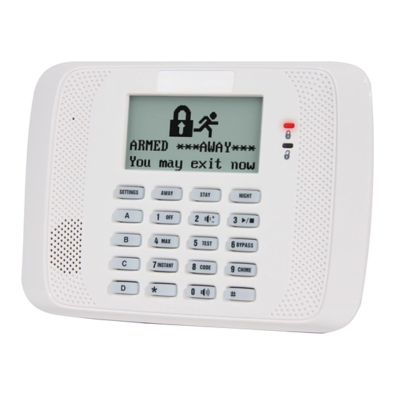
4-Line Alpha Display
Custom Zone Designators
= System ARMED
= System NOT ARMED
= READY to Arm
= NOT READY to Arm
Arming Keys
Result
Displays Settings Menu*:
1 Set Time/Date
2 View Event Log
3 Reboot Keypad
4 Set User Code**
Control Panel Terminal Strip
AUX
AUX DATA
Black (Gnd)
Red (+12vdc)
Green (Data To Control)
Yellow (Data From Control)
DATA
IN
OUT
Advertisement

Related Manuals for Honeywell ADEMCO 6162RF


Summary of Contents for Honeywell ADEMCO 6162RF
- Page 1 ADEMCO 6162RF Keypad / Transceiver – Installation and Setup Guide Alphanumeric Addressable Keypad/Transceivers for use with Honeywell Control Panels; incorporates functions of a High RF Receiver and a 5800 Transmitter module. 4-Line Alpha Display • Supports wireless key transmitters Custom Zone Designators (e.g., 5834-4) and bi-directional...
- Page 2 APPLICATION GUIDELINES FOR THE 6162RF Table 1 – Application Guidelines If… And… Then… • This is the only You want to use both Set the keypad to a device address assigned to the desired partition.* • transceiver on the receiver and Enable the receiver.
- Page 3 Table 2 – 6162RF Programming (continued) STEP DESCRIPTION DISPLAY CHOICES Press to continue. (cont.) Enable High Security Mode. Enter [1] to select High Security Mode. 1 = ON HIGH SECURITY (Enable) OFF [1 = ON] Note: If the High Security mode is enabled, the 6162RF will only recognize encrypted devices.
- Page 4 REFER TO INSTALLATION INSTRUCTIONS FOR THE CONTROL PANEL WITH WHICH THIS DEVICE IS USED FOR WARRANTY INFORMATION AND LIMITATIONS OF THE ENTIRE ALARM SYSTEM. WARRANTY INFORMATION: For the latest warranty information, please go to www.honeywell.com/security/hsc/resources/wa DOCUMENTATION AND ONLINE SUPPORT: For the latest documentation and online support information, please go to: http://www.security.honeywell.com/hsc/resources/MyWebTech...