Makita DHS680 Technical Information
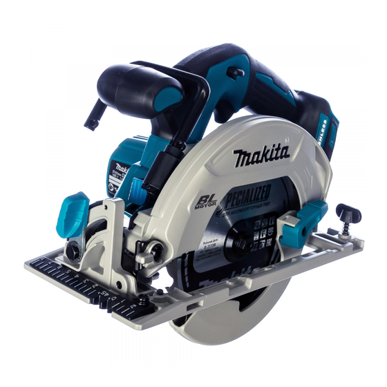
165mm 6-1/2" cordless circular saw
Hide thumbs
Also See for DHS680:
- Instruction manual (100 pages) ,
- Instruction manual (23 pages) ,
- Instruction manual (89 pages)
Table of Contents
Advertisement
T
ECHNICAL INFORMATION
Models No.
Description
C
ONCEPT AND MAIN APPLICATIONS
Model DHS680 is a 165mm (6-1/2") Cordless circular saw powered by
18V Li-ion battery.
Its main features are:
• High-efficiency Brushless motor to provide compact and lightweight
design and high power.
• Lightweight design achieved by using durable but light magnesium die-cast
for base, blade case and safety cover
• Automatic speed control: automatically changes the cutting speed
according to load conditions.
Note: 1.3Ah Li-ion battery of BL1815 cannot be used for this model.
S
pecification
Specification
Voltage: V
Capacity: Ah
Energy capacity: W
Battery
Cell
Charging time (approx.): min
Max output (W)
No load speed: min
¹ = rpm
ˉ
Blade size: mm (")
Max cutting capacities:
mm (")
Electronic current limiter
for overload protection
Electric brake
Soft start
LED Job light
Weight according to
EPTA-Procedure 01/2003 : kg (lbs)
*3: With TCT saw blade
S
tandard equipment
TCT saw blade
Hex wrench 5
Rip fence (for some countries only)
*4 Plastic carrying case, Battery and charger are not supplied with "Z" model
Note: The standard equipment may vary by country or model variation.
O
ptional accessories
Guide rail adapter
Various TCT saw blade
Rip fences
Dust nozzle
DHS680
165mm (6-1/2") Cordless Circular Saw
Model
Diameter
All countries except North America: 20 (13/16)
Hole diameter
North America: 15.88 (5/8)
at 0°
at 45°
at 50°
*
3
Dust nozzle (for European countries only)
Plastic carrying case*
Battery*
4
Fast charger DC18RC
Charger DC18SD
Charger DC24SC
Automotive charger DC18SE
H
*1 With battery BL1830/ BL1840/ BL1850
*2 With battery BL1815N/ BL1820
DHS680
18
1.5, 2.0, 3.0, 4.0, 5.0
27, 36, 54, 72, 90
Li-ion
15, 24, 22, 36, 45
with DC18RC
680
5,000
165 (6-1/2)
57 (2-1/4)
41 (1-5/8)
37 (1-7/16)
Yes
Yes
Yes
Yes
3.1 (6.8)*
2
3.3 (7.3)*
1
4
Four port multi charger DC18SF
Two port multi fast charger DC18RD
Battery BL1815N
Battery BL1820
OFFICIAL USE
for ASC & Sales Shop
PRODUCT
P 1/ 18
W
L
Dimensions: mm (")
350 (13-3/4)*
Length (L)
336 (13-1/4)*
Width (W)
170 (6-11/16)
Height (H)
238 (9-3/8)
Charger*
4
Battery cover
Battery BL1830
Battery BL1840
Battery BL1850
1
2
Advertisement
Table of Contents

Related Manuals for Makita DHS680


Summary of Contents for Makita DHS680
- Page 1 DHS680 Description 165mm (6-1/2") Cordless Circular Saw ONCEPT AND MAIN APPLICATIONS Model DHS680 is a 165mm (6-1/2”) Cordless circular saw powered by 18V Li-ion battery. Its main features are: • High-efficiency Brushless motor to provide compact and lightweight design and high power.
- Page 2 Shoulder pin 6-7 [2] LUBRICATION Apply Makita grease FA No.2 to the following portions designated with the black triangle, and apply lubricant oil VG100 to the following portions designated with the white triangle to protect parts and product from unusual abrasion.
- Page 3 P 3/ 18 epair [3] DISASSEMBLY/ASSEMBLY [3] -1. Base DISASSEMBLING (1) Set the cutting depth of the machine to maximum, and remove saw blade as drawn in Fig. 2. Fig. 2 1. Locking Spindle with Shaft lock lever, 2. Opening Safety cover fully, remove Saw blade. remove Hex flange head bolt and and Inner flange.
- Page 4 P 4/ 18 epair [3] DISASSEMBLY/ASSEMBLY [3] -1. Base (cont.) DISASSEMBLING (1) Separate Base section from the machine. (Fig. 4) Fig. 4 Base section (2) Disassemble Angular guide section as drawn in Fig. 5. Fig. 5 2. Remove M6x20 Hex bolt, Lever 45 and Flat washer 6. 1.
- Page 5 P 5/ 18 epair [3] DISASSEMBLY/ASSEMBLY [3] -1. Base (cont.) ASSEMBLING (1) Assemble the removed component parts to the new Base by reversing the disassembly procedure. (Refer to Figs. 6, 5 and 3.) Note in Assembling: Do not forget to assemble Flat washers 6 and 7, and assemble Lever 45 to Angular guide section as drawn in Fig. 7. Fig.
- Page 6 P 6/ 18 epair [3] DISASSEMBLY/ASSEMBLY [3] -2. Depth guide (cont.) DISASSEMBLING (2) Disassemble Depth guide section as drawn in Fig. 9. Fig. 9 1. Loosen M6 Hex nut 2. Remove Stop ring E-8 with a slotted 3. Remove M6 Hex nut, Lever 45 with Lever 45.
- Page 7 P 7/ 18 epair [3] DISASSEMBLY/ASSEMBLY [3] -2. Depth guide (cont.) ASSEMBLING (1) Assemble Depth guide to Base as drawn in Fig. 10. Fig. 10 1. Sandwitch Depth guide between Flat washers 6, 2. Pass M6x90 Cap square neck bolt to Motor housing and set them to Blade case.
- Page 8 P 8/ 18 epair [3] DISASSEMBLY/ASSEMBLY [3] -2. Depth guide (cont.) ASSEMBLING (2) Adjust the locked position of Lever 45 so that it always leans toward base plate from 0 - 30° when the machine is adjusted to the required cutting depth. (Fig. 11) Fig.
- Page 9 P 9/ 18 epair [3] DISASSEMBLY/ASSEMBLY [3] -3. Rotor (cont.) DISASSEMBLING (1A) If Ball bearing 609LLB remains in Blade case, it is difficult to pull off Rotor from Motor housing by hand. Use a vise as drawn in Fig. 12A. Fig.
- Page 10 P 10/ 18 epair [3] DISASSEMBLY/ASSEMBLY [3] -3. Rotor (cont.) ASSEMBLING Assemble Rotor by reversing the disassembly procedure. Note: Be careful not to pinch your fingers between Rotor and Stator complete. (Refer to Fig. 12.) [3] -4. Safety cover DISASSEMBLING Disassemble Safety cover as drawn in Fig.
- Page 11 P 11/ 18 epair [3] DISASSEMBLY/ASSEMBLY [3] -5. Gear section DISASSEMBLING (1) Disassemble Safety cover as drawn in Fig. 8. (2) Remove Bearing box section from Blade case, then disassemble Gear section as drawn in Fig. 15. Fig. 15 1. Remove two M5x16 Pan head screws, 2.
- Page 12 P 12/ 18 epair [3] DISASSEMBLY/ASSEMBLY [3] -6. Top guide ASSEMBLING Adjust and assemble Top guide as drawn in Fig. 16. Fig. 16 1. Adjust 0° notch line of Top guide so that it comes to 2. Tighten Top guide with M5x8 Pan head screw 0.5 mm line of the base metal of the saw blade.
- Page 13 P 13/ 18 epair [3] DISASSEMBLY/ASSEMBLY [3] -9 Adjustment of Bevel angle of Base to Saw blade Caution: It is necessary to attach saw blade to adjust the angle of Saw blade to Base. Therefore, DO NOT ATTACH BATTERY to avoid unexpected start of the machine. (1) Set the cutting depth of the machine to maximum with the bevel angle adjusted to 90°, then attach Saw blade.
- Page 14 P 14/ 18 epair [3] DISASSEMBLY/ASSEMBLY [3] -10 Adjustment of Base to Saw Blade (1) Remove batteries from the machine. (2) Set the cutting depth of the machine to maximum, and attach Saw blade. (3) Adjust parallel position of Base to Saw Blade as drawn in Fig. 20. Note: Tighten both Lever 45 for bevel setting and Lever 45 for depth setting fully before adjusting.
- Page 15 P 15/ 18 ircuit diagram Fig. D-1 Color index of lead wires' sheath Black Blue Orange Green White Yellow Switch unit Micro Flag terminal with lock switch (#250, t=0.8mm) Stator Terminal Switch Lead wires (26AWG*) Connector Tape Straight terminal Polyolefin Polyolefin with lock tube...
- Page 16 P 16/ 18 iring diagram Fig. D-3 Tighten Lead wires between Connector and the ends of Ribs D and E. Route Lead wires connected with Connector into this groove. Rib F Rib D Connector Rib G Rib E Route Lead wires of Connector Route Lead wires of Connector between Ribs D and E.
- Page 17 P 17/ 18 epair [4] TROUBLE SHOOT Whenever you find any trouble in your machine, first, refer to this list to check the machine for solution. Fig. T-1 Note in Repairing Star mark (1) Use the full charged battery that has a star mark. (Fig. T-1) (2) When Housing is disassembled, check the conditions of the electrical parts (Connectors, Lead wires, Switches, etc.), Rotor, Stator, Gear section, etc.
- Page 18 P 18/18 epair [4] TROUBLE SHOOT Check List for Trouble Shooting 1 Check the items from top of the following list. (Description of the item is referred to Circuit diagram in Fig. D-1. After corrective action, return to the start of Trouble shooting and re-check again. Symptom Cause Corrective action...